Audiophony PA DZ-MATRIX User manual
PRESENTATION LEAFLET
H11393 / H11395 / H11396 / H11397 / H11398 / H11399 / H11400 - Version 1 / 10-2022
The complete user manual and software updates are available for download at www.
audiophony-pa.com
English DZ-MATRIX - Digital matrix
Page 2
1 - Please read carefully :
We strongly recommend to read carefully and understand the safety instructions before
attempting to operate this unit.
2 - Please keep this manual :
We strongly recommend to keep this manual with the unit for future reference.
3 - Operate carefully this product :
We strongly recommend to take into consideration every safety instruction.
4 - Follow the instructions:
Please carefully follow each safety instruction to avoid any physical harm or property
damage.
5 - Avoid water and wet locations :
Do not use this product in rain, or near washbasins or other wet locations.
6 - Installation :
We strongly encourage you to only use a xation system or support recommended by the
manufacturer or supplied with this product. Carefully follow the installation instructions
and use the adequate tools.
Always ensure this unit is rmly xed to avoid vibration and slipping while operating as
it may result in physical injury.
7 - Ceiling or wall installation :
Please contact your local dealer before attempting any ceiling or wall installation.
8 - Ventilation :
The cooling vents ensure a safe use of this product, and avoid any overheating risk.
Do not obstruct or cover these vents as it may result in overheating and potential
physical injury or product damage. This product should never been operated in a
closed non-ventilated area such as a ight case or a rack, unless cooling vents are
provided for the purpose .
9 - Heat exposure :
Sustained contact or proximity with warm surfaces may cause overheating and product
damages. Please keep this product away from any heat source such as a heaters,
ampliers, hot plates, etc...
Sound levels
Our audio solutions deliver important sound pressure levels
(SPL) that can be harmful to human health when exposed
during long periods. Please do not stay in close proximity of
operating speakers.
WARNING
1 - Safety information
Important safety information
Symbols used
Any maintenance procedure must be performed by a CONTEST
authorised technical service. Basic cleaning operations must tho-
roughly follow our safety instructions.
This product contains non-isolated electrical components. Do not
undertake any maintenance operation when it is switched on as it
may result in electric shock.
This unit is intended for indoor use only. Do not use it in a wet, or
extremely cold/hot locations. Failure to follow these safety instruc-
tions could result in re, electric shock, injury, or damage to this
product or other property.
WARNING : This unit contains no user-serviceable parts. Do not open the housing or attempt
any maintenance by yourself. In the unlikely even your unit may require service, please contact your
nearest dealer.
In order to avoid any electrical malfunction, please do not use any multi-socket, power cord extension or
connecting system without making sure they are
perfectly isolated and present no defect.
10 - Electric power supply :
This product can only be operated according to a very specic voltage. These information
are specied on the label located at the rear of the product.
11 - Power cords protection:
Power-supply cords should be routed so that they are not likely to be walked on or
pinched by items placed upon or against them, paying particular attention to cords at
lugs, convenience receptacles and the point where they exit from the xture.
12 - Cleaning precautions :
Unplug the product before attempting any cleaning operation. This product should be
cleaned only with accessories recommended by the manufacturer. Use a damp cloth
to clean the surface. Do not wash this product.
13 - Long periods of non use :
Disconnect the unit’s main power during long periods of non use.
14 - Liquids or objects penetration :
Do not let any object penetrate this product as it may result in electric shock or re.
Never spill any liquid on this product as it may inltrate the electronic components and
result in electric shock or re.
15 - This product should be serviced when :
Please contact the qualied service personnel if :
- The power cord or the plug has been damaged.
- Objects have fallen or liquid has been spilled into the appliance.
- The appliance has been exposed to rain or water.
- The product does not appear to operate normally.
- The product has been damaged.
16 - Inspection/maintenance :
Please do not attempt any inspection or maintenance by yourself. Refer all servicing
to qualied personnel.
17 - Operating environment :
Ambient temperature and humidity: +5 - +35°C, relative humidity must be less than
85% (when cooling vents are not obstructed).
Do not operate this product in a non-ventilated, very humid or warm place.
Recycling your device
• As HITMUSIC is really involved in the environmental cause,
we only commercialise clean, ROHS compliant products.
• When this product reaches its end of life, take it to a
collection point designated by local authorities. The separate
collection and recycling of your product at the time of
disposal will help conserve natural resources and ensure
that it is recycled in a manner that protects human health
and the environment.
This symbol signals an important safety precaution.
IMPORTANT
The CAUTION symbol signals a risk of product deterioration.
CAUTION
The WARNING symbol signals a risk to the user’s physical integrity.
The product may also be damaged.
WARNING
Instructions and recommendations

EnglishDZ-MATRIX - Digital matrix
Page 3
3 - Overview
The DZ-MATRIX is the heart of the matrixing system, its peripheral controllers, input/output boxes and microphone
desk complete the series dedicated to public address, message broadcasting and zone management.
The complete software allows to assign all inputs and outputs and to process the signal according to the needs
of the installation.
The numerous mesh possibilities make it suitable for installations in shopping malls, restaurants, hotels,
museums, conference rooms, etc. where the number of entrances and the area of diffusion require precise
parameterization.
3 - 1 - FRONT PANEL
1 - Display
Displays device information such as name, ID, current preset and communication status.
2 - Introduction
a- Displays the name of the device.
b- Displays the preset currently in use.
c- Displays the ID of the device. The ID is obtained automatically when the device is properly connected.
d- Connection indicator between the PC and the device. If the connection is good, the two icons will flash
alternately.
e- DSP connection indicator.
2 - ANALOG
Analog input indicators. The green LED indicates the presence of a signal, the red LED indicates the clipping
of the signal of the corresponding input.
3 - RD
RD remote input indicators. The green LED indicates the presence of a signal, the red LED indicates the
clipping of the signal of the corresponding input.
4 - ANALOG
Analog output indicators. The green LED indicates the presence of a signal, the red LED indicates the
clipping of the signal of the corresponding input.
5 - RD
RD remote output indicators. The green LED indicates the presence of a signal, the red LED indicates the
clipping of the signal of the corresponding input.

English DZ-MATRIX - Digital matrix
Page 4
3 - 2 - BACK PANEL
1 - Power supply input
The input voltage may vary from 100 V to 240 VAC, 50-60 Hz.
If you have to replace the fuse, replace it with a fuse of the same value.
2 - Compartment for the optional extension
3 - LAN
Port for Ethernet connection, 10/100M adaptive, with DHCP function.
4 & 5 - GPI
This function is used to control the input / output priority / mute all outputs of channels 1-8.
6 - ON <> OFF
Enables or disables the Ethernet port.
7 & 8 - RD 9/10, 11/12
RD port for connecting a remote control accessory such as DZ-BOX22, DZ-CTL, DZ-CTL2OUT, DZ-
EXPAND and DZ-MICDESK.
This port transmits and receives AES3 digital audio and control data.
9 - RELAY
Dry contacts whose ON/OFF status can be individually controlled in the System menu. They are usually
used as switches for third party electrical equipment.
Attention: 24V DC, control current : Less than 500 mA.
10 - RS232
This interface is used to remotely control the parameters of the DZ-MATRIX, such as changing a preset or
changing the gain of a channel.
11 - INPUT
Euroblock connector with 8 balanced analog inputs.
12 - OUTPUT
Euroblock connector with 8 balanced analog outputs.
6 - STATUS
FAULT : Red LED indicating a DSP malfunction. The information is relayed on the display.
COMM : Green LED indicating the communication status between the PC and the device. The LED
flashes during data transfer. It remains off if there is a problem.
POWER : Blue LED indicating that the unit is powered on.

EnglishDZ-MATRIX - Digital matrix
Page 5
Analog I/O 8 x 8
Connectors Euroblock 8 x 3 pins, 5 mm pitch
CODEC CS5368-CQZ 24 bits, 48K A/D
CS5368-CQZ 24 bits, 48K D/A
Inputs
Balanced
Gain settings 0 dB to 50 dB, step=12 dB
Input Impedance 6.5 KΩ
Phantom power +48 VDC, 10 mA max per input
THD+N < 0.01%, 20 Hz ~ 20 KHZ, 0 dBu
Maximum level 20 dBu (7.746 Vrms)
Frequency response 20 Hz ~ 20 KHz, 0 dB +/-1.5 dB
Dynamic range -126 dBu
Cross talk -70 dB max, A weighted 20 Hz ~ 20 KHz, +20dB
Outputs
Balanced
Impedance 240 Ω
Maximum level +20 dBu
Frequency response 20 Hz ~ 20 KH, 0 dB +/-1.5 dB
Dynamic range -107 dBu max, A weighted
Cross talk -87 dB, A weighted
Indicators
Signal -30 dBu, green LED
Clip +17 dBu, red LED
DSP
Processor SHARC ADSP-21489, 450 MHz
Word lenght 32 / 64 bits oating point
Dimensions
L x H x D 483 x 44 x 256 mm

English DZ-MATRIX - Digital matrix
Page 6
1 - Mic input
3-pin XLR female connector for the gooseneck electret
microphone (included). It uses phantom power controlled by the
DZ-MATRIX software.
2 - Display
It displays the selected zones, the volume and the identification
number.
3 - BUSY/COM operation indicators
When the communication with the DZ-MATRIX is correct, the
green LED flashes. The red BUSY LED lights up when another
mic is used.
4 - Signal indicator LEDs
The green LED indicates the presence of a signal when the
microphone is activated. The red LED indicates the clipping
limit.
5 - VOLUME
It controls the microphone volume for each selected zone. By
pressing the button, it selects all zones.
6 - SCROLL
It allows you to select one or more zones by turning the knob to
the left or right and pressing it to confirm.
7 - TALK
When the button is pressed, the chime sounds and the red ring on the microphone lights up, indicating that you can speak.
8 - RD Port
Connection to the DZ-MATRIX. The maximum length of the CAT 5E(or better) cable is 100 meters.
9 - USB port
This port is used to load WAV / MP3 files for the chime sound. The maximum duration of the chime is 4 seconds.
4 - Peripheral devices
5 - 1 - DZ-MICDESK
Micro zone manager desk
DZ-MICDESK
2
1
3
4
89
5
6
7
Power supply 24 VDC (powered by DZ-MATRIX or DZ-EXPAND)
Audio output 0 dBV, balanced, RJ45 connector
Gooseneck microphone (included) Unidirectional electret condenser microphone
Total harmonic distortion < 0.01 %
RD port Transmits and receives AES3 digital audio and control data to the DZ-
MATRIX. RJ45 port.
USB port Loading WAV / MP3 les for chime sound
Volume control Microphone volume control and all-zone switch
Zone selector Can address 1 to 64 dierent zones
Display Displays device information: ID, volume, zone selector
Indicators Signal (green), Input peak (red), Busy (red), Comm (green)
Finishing Steel, black paint
Dimensions (L x D x H) 176 x 61.8 x 162.4 mm
Net weight 0.8 Kg

EnglishDZ-MATRIX - Digital matrix
Page 7
5 - 2 - DZ-EXPAND
Expander to connect multiple controllers to the matrix.
FRONT PANEL
BACK PANEL
1, 2and 3- Indicate the status of the activity of each port.
4- Indicates that the DZ-EXPAND is powered on
1- DC24V ~ 1000mA power supply input. When there are too many devices connected to the RD EXP port of
DZ-EXPAND and the POWER indicator on the front panel of DZ-EXPAND is off, please connect an external
DC24V 1000mA power supply.
2- RD connections for DZ-CTL / DZ-CTL2OUT (remote device control data only) / DZ-PAD.
3- RD connection for DZ-MICDESK / DZ-CTL2OUT / DZ-BOX22 (remote audio control and data transport
devices).
4- RD connection to the DZ-MATRIX.
2 3 41
1 2 3 4
English DZ-MATRIX - Digital matrix
Page 8
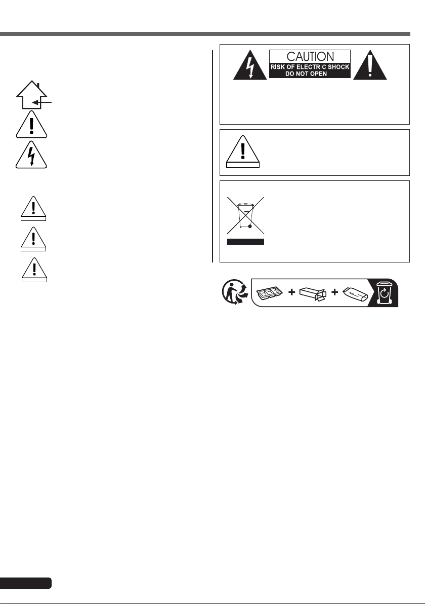
5 - 3 - DZ-CTL
Volume control box for DZ-MATRIX.
LINK RJ45 connection for
additional remote controls
Turn the knob to the
left or right to adjust the
volume.
Press the knob to
access the input and
output routing functions.
Display: Shows the
volume level and
signal level for a
dedicated output.
Also displays the
routing settings.
RJ45 connector for
connection to the DZ-
MATRIX.
Maximum 100 meters of
CAT 5E(or better) cable
length.
DZ-SERIES
IN OUT/LINK
DZ-SERIES
IN OUT/LINK
FRONT PANEL
CONNECTION CARD
LCD display
Volume setting -ꝏ ~ +15 dB
Ports
RD to DZ-MATRIX network, RJ45, maximum 100 m CAT 5E(or better) cable
RD LINK network, RJ45, maximum 100 m CAT 5E(or better) cable
Dimensions (L x H x D) 147 x 86 x 47 mm

EnglishDZ-MATRIX - Digital matrix
Page 9
5 - 4 - DZ-CTL2OUT
Volume control box for channels 9/10 or 11/12 of the matrix with two analog outputs.
2 analog line outputs
assigned to the RD 9/10
or 11/12 ports of the DZ-
MATRIX
Turn the knob to the
left or right to adjust
the volume.
Press the knob to
access the input
and output routing
functions.
Display: Shows the
volume level and
signal level for a
dedicated output.
Also displays the
routing settings.
RJ45 connector for
connection to the DZ-
MATRIX.
Maximum 100 meters
of CAT 5E(or better)
cable length.
DZ-SERIES
+-G+-G
DZ-SERIES
+-G+-G
FRONT PANEL
CONNECTION CARD
2 analog outputs
Balanced
Connectors 2 terminals 3 pins 5 mm pitch
Impedance 240 Ohms
Maximal power output + 20 dBu
Frequency response at 0 dB 20 Hz ~ 20 KHz +/- 1.5 dB
Dynamic range -107 dB max., A weighted
Crosstalk -87 dB max. A weighted
LCD display
Volume setting -ꝏ ~ +15 dB
Ports
RD to DZ-MATRIX network, RJ45, maximum 100 m CAT 5E(or better) cable
Dimensions (L x H x D) 147 x 86 x 47 mm

English DZ-MATRIX - Digital matrix
Page 10
134 2
1 - RD IN port
Connection to the DZ-MATRIX or DZ-EXPAND.
The maximum length of the CAT 5E(or better) cable is 100 meters.
2 - RD EXP port
LINK connection for additional controllers (maximum 4 controllers).
3 - Power supply connector
Auxiliary power input +24V DC, required to connect two or more DZ-PADs.
4 - Touch control panel
Displays connection status, ID number, volume, model, channel selection and other information.
5 - 5 - DZ-PAD
Touch control panel for DZ-MATRIX
EnglishDZ-MATRIX - Digital matrix
Page 11
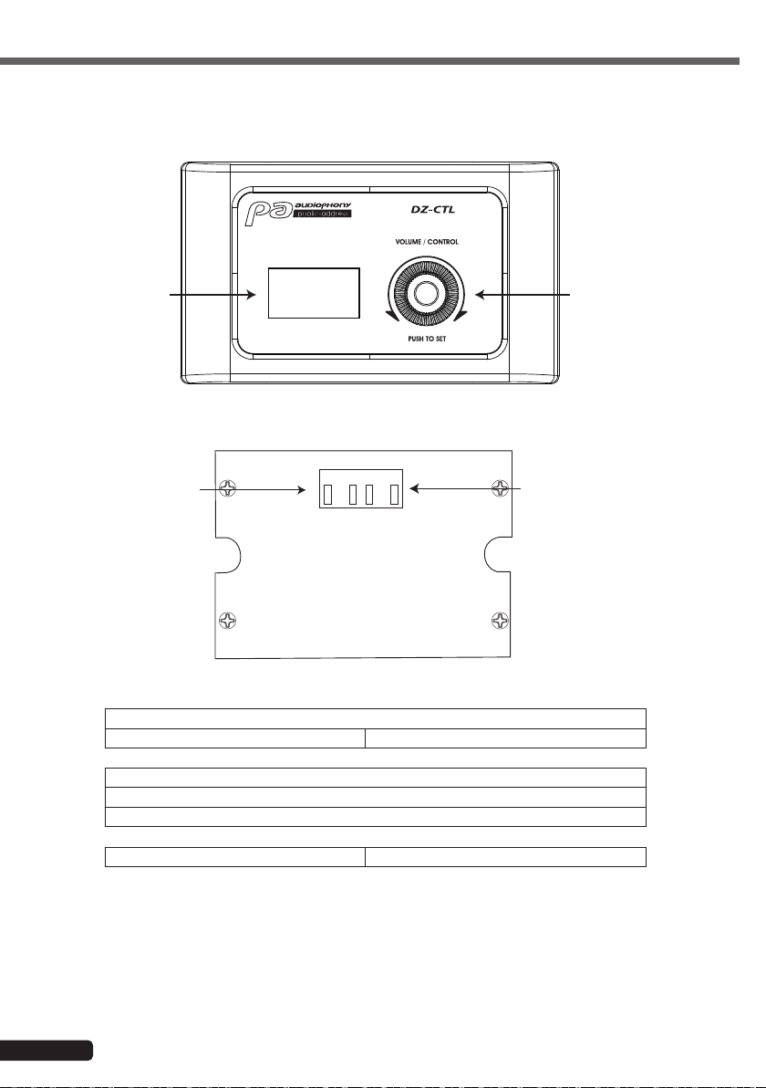
5 - 6 - DZ-BOX22
Connection box for microphone or line to be assigned to channels 9/10 or 11/12 of the matrix with 2 analog outputs.
FRONT PANEL
CONNECTION CARD
0 10
PHANTOM 48V INPUT
OUTPUT
ON OFF
A/MIC B
SIGN
CLIP
SIGN
CLIP
A B
A
MIC A
B
+-G+-G
0 10
PHANTOM 48V INPUT
OUTPUT
ON OFF
A/MIC B
SIGN
CLIP
SIGN
CLIP
A B
A
MIC A
B
+-G+-G
Analog line inputs A &
B assigned to channels
9/10 or 11/12 of the
DZ-MATRIX.
Mic input.
Microphone input level adjustment
Switchable 48V phantom power for electret microphones.
Status indicators for input
signals A and B.
Status indicators for output
signals A and B.
RJ45 connector for connection to
the DZ-MATRIX.
Maximum 100 meters of CAT
5E(or better) cable length.
2 analog line outputs
assigned to the RD 9/10
or 11/12 ports of the DZ-
MATRIX
Inputs
Balanced
Connectors 3 pins XLR and RCA
Imprdance 5.1 KΩ
THD+N < 0.01 % typ 20-20 KHz, 0 dBu
Max input level 20 dBu
Frequency response 20 Hz ~ 20 KHz +/- 1.5 dB
Dynamic range -107 dB max., A weighted
Crosstalk -87 dB max. A weighted
Outputs
Balanced
Connectors 2 terminals 3 pins 5 mm pitch
Impedance 240 Ohms
Max output level +20 dBu
Frequency response 20 Hz ~ 20 KHz +/- 1.5 dB
Dynamic range -107 dB max., A weighted
Crosstalk -87 dB max. A weighted
Indicators
Signal -30 dBu, green
Clip +17 dBu, red
Ports
RD to DZ-MATRIX network, RJ45, maximum 100 m CAT 5E(or better) cable
Dimensions (L x H x D) 147 x 86 x 47 mm

English DZ-MATRIX - Digital matrix
Page 12
0 10
PHANTOM48V INPUT
OUTPUT
ON OFF
A/MIC B
SIGN
CLIP
SIGN
CLIP
A B
A
MICA
B
DZ-MATRIX
LAPTOP 100 V
AMPLIFER
CEILING SPEAKERS
CEILING SPEAKERS
CEILING SPEAKERS
STEREO POWERED SYSTEM
DZ-CTL
DZ-CTL
DZ-PAD
DZ-EXPAND
DZ-BOX22
SMARTPHONE
MICROPHONE
DZ-MICDESK
MULTIMEDIA PLAYER
WEBRADIO
SWITCH
4 - Wiring principle

Because AUDIOPHONY®takes the utmost care in its products to make sure you only get the best possible quality, our products are
subjects to modifications without prior notice. That is why technical specifications and the products physical configuration might differ
from the illustrations.
Make sure you get the latest news and updates about the AUDIOPHONY®products on www.audiophony-pa.com
AUDIOPHONY®is a trademark of HITMUSIC S.A.S - Zone Cahors sud - 46230 FONTANES - FRANCE
This manual suits for next models
7
Table of contents
Popular Recording Equipment manuals by other brands

Individual Computers
Individual Computers Keyrah v3 Short manual

Kurzweil
Kurzweil SP7 Grand quick start

Yellowtec
Yellowtec m!ka Mic Arm Briefing Book

Tigertronics
Tigertronics SignaLink SL-1+ Installation & operation

Jupiter Avionics
Jupiter Avionics JA95-N01 Installation and operating manual

Strymon
Strymon BRIGADIER dBucket Delay quick start guide


