Audioplex 25 VOLT STEREO VOLUME CONTROL User manual

Attenuator type: Tapped auto transformer.
Switch: 12 position rotary, make-before-break contacts,
low torque specifications for smooth feel.
Connector: Screw-tight type, non-removable.
Input Power Rating: 25 volts: 25 Watts RMS continuous, 35 Hz-20 KHz.
Frequency Response: +0, -21/2 dB worst case (-6 dB tap), +0, -1 dB all other taps,
35 Hz-20 KHz. Most controls better these specifications.
Transformers: Grain-oriented, high silicon steel laminations.
Attenuation: -20 dB in 10 steps, 6 steps @ -2 dB each, 2 step @ 4 dB, last step OFF.
Mounting: Fits in most standard single electrical junction boxes,
depth less than 2 1/4".
1. Make connections by stripping wire insulation back about 3/16". Twist any loose strands tightly.
2. Insert the wires from the amplifier into the INPUT openings of the connector, hot to hot and ground
to ground, then tighten screws. Check for stray wire strands that might cause a short circuit. Make
sure the metal part of the screw connector engages the bare wire, NOT the insulation!
3. Similarly, connect speaker wires to the control OUTPUT openings and tighten screws.
4. Select the appropriate POWER and IMPEDANCE taps on the matching transformer and connect it's
OUTPUT to the speaker voice coil terminals.
5. Install control in its operating location. Suggestion: Leave control 3 or 4 positions CCW from
maximum before firing-up the system for the first time to avoid "blasting" the speakers, while still
having enough sound to observe operation.
AUDIOPLEX TECHNOLOGY
404 GWH, P.O. BOX 440
MELVIN VILLAGE, N.H. 03850
1-800-257-2077 IN N.H. 1-603-544-8601
FAX: 1-603-544-8901
E-MAIL: [email protected]
INSTALLATION
Installation must be made by qualified service personnel, and must meet all local codes.
TECHNOLOGY
INSTALLATION MANUAL
1999 -4/22/99
25 VOLT STEREO VOLUME CONTROL

WARRANTY:
Your AUDIOPLEX TECHNOLOGY Stereo Speaker Volume Control is covered by a Lifetime
warranty against any defects in workmanship and materials. Any defects will be remedied without charge
for labor or parts.
Damage incurred by shipping or accident is not considered to be a defect, and not covered by this
warranty. AUDIOPLEX TECHNOLOGY, is not responsible for defective operation caused by abuse or by
modification or service by any unauthorized person or agency.
The product must be properly installed and operated according to instructions for the warranty to apply.
Any necessary servicing must be done by AUDIOPLEX TECHNOLOGY. The product must be returned
expenses prepaid, with written authorization from the company. The product must be shipped with the
proof of purchase and in the original carton and packing material to avoid damage.
This warranty gives you specific legal rights. You may have other rights which vary from state to state.
WIRING DIAGRAM
- R +
+ L -
25 / 70 VOLT
VOLUME CONTROL
(SIDE VIEW)
- R +
+ L -
AMPLIFIER
SPEAKER OUTPUT
L+
OUTPUT INPUT
L+R+ R+L- L-R- R-
70(25) VOLT
MATCHING
TRANSFORMER
70(25) VOLT
MATCHING
TRANSFORMER
1999 - 4/22/99

Attenuator type: Tapped auto transformer.
Switch: 12 position rotary, make-before-break contacts,
low torque specifications for smooth feel.
Connector: Screw-tight type, non-removable.
Input Power Rating: 70 volts: 25 Watts RMS continuous, 35 Hz-20 KHz.
Frequency Response: +0, -21/2 dB worst case (-6 dB tap), +0, -1 dB all other taps,
35 Hz-20 KHz. Most controls better these specifications.
Transformers: Grain-oriented, high silicon steel laminations.
Attenuation: -34 dB in 12 steps, 8 steps @ -3 dB each, 1 step @ 4 dB, 1 step
@ -6 dB, last step OFF..
Mounting: Fits in most standard single electrical junction boxes,
depth less than 2 1/4".
1. Make connections by stripping wire insulation back about 3/16". Twist any loose strands tightly.
2. Insert the wires from the amplifier into the INPUT openings of the connector, hot to hot and ground
to ground, then tighten screws. Check for stray wire strands that might cause a short circuit. Make
sure the metal part of the screw connector engages the bare wire, NOT the insulation!
3. Similarly, connect speaker wires to the control OUTPUT openings and tighten screws.
4. Select the appropriate POWER and IMPEDANCE taps on the matching transformer and connect it's
OUTPUT to the speaker voice coil terminals.
5. Install control in its operating location. Suggestion: Leave control 3 or 4 positions CCW from
maximum before firing-up the system for the first time to avoid "blasting" the speakers, while still
having enough sound to observe operation.
AUDIOPLEX TECHNOLOGY
404 GWH, P.O. BOX 440
MELVIN VILLAGE, N.H. 03850
1-800-257-2077 IN N.H. 1-603-544-8601
FAX: 1-603-544-8901
E-MAIL: [email protected]
TECHNOLOGY
INSTALLATION
Installation must be made by qualified service personnel, and must meet all local codes.
INSTALLATION MANUAL
1999 - 4/22/99
70 VOLT STEREO VOLUME CONTROL

WARRANTY:
Your AUDIOPLEX TECHNOLOGY Stereo Speaker Volume Control is covered by a 10 year warranty
against any defects in workmanship and materials. Any defects will be remedied without charge for labor
or parts during this period of time following the date of purchase.
Damage incurred by shipping or accident is not considered to be a defect, and not covered by this
warranty. AUDIOPLEX TECHNOLOGY, is not responsible for defective operation caused by abuse or by
modification or service by any unauthorized person or agency.
The product must be properly installed and operated according to instructions for the warranty to apply.
Any necessary servicing must be done by AUDIOPLEX TECHNOLOGY. The product must be returned
expenses prepaid, with written authorization from the company. The product must be shipped with the
proof of purchase and in the original carton and packing material to avoid damage.
This warranty gives you specific legal rights. You may have other rights which vary from state to state.
WIRING DIAGRAM
- R +
+ L -
25 / 70 VOLT
VOLUME CONTROL
(SIDE VIEW)
- R +
+ L -
AMPLIFIER
SPEAKER OUTPUT
L+
OUTPUT INPUT
L+R+ R+L- L-R- R-
70(25) VOLT
MATCHING
TRANSFORMER
70(25) VOLT
MATCHING
TRANSFORMER
1999 - 4/22/99

Attenuator type: Tapped auto transformer.
Switch: 12 position rotary, make-before-break contacts,
low torque specifications for smooth feel.
Connector: Screw-tight type, non-removable.
Equivalent Power Input Rating: 70 volts: 25 Watts RMS continuous, 25 volts: 10 Watts
RMS continuous, 35 Hz-20 KHz.
Frequency Response: +0, -21/2 dB worst case (-6 dB tap), +0, -1 dB
all other taps, 35 Hz-20 KHz. Most controls
better these specifications.
Transformers: Grain-oriented, high silicon steel laminations.
Attenuation: -20 dB in 10 steps, 6 steps @ -2 dB each, 2 step
@ 4 dB, last step OFF.
Mounting: Fits in most standard single electrical junction
boxes, depth less than 2 1/4".
1. Make connections by stripping wire insulation back about 3/16". Twist any loose strands tightly.
2. Insert the wires from the amplifier into the INPUT openings of the connector, hot to hot and ground
to ground, then tighten screws. Check for stray wire strands that might cause a short circuit. Make
sure the metal part of the screw connector engages the bare wire, NOT the insulation!
3. Similarly, connect speaker wires to the control OUTPUT openings and tighten screws.
4. Select the appropriate POWER and IMPEDANCE taps on the matching transformer and connect it's
OUTPUT to the speaker voice coil terminals.
5. Install control in its operating location. Suggestion: Leave control 3 or 4 positions CCW from
maximum before firing-up the system for the first time to avoid "blasting" the speakers, while still
having enough sound to observe operation.
AUDIOPLEX TECHNOLOGY
404 GWH, P.O. BOX 440
MELVIN VILLAGE, N.H. 03850
1-800-257-2077 IN N.H. 1-603-544-8601
FAX: 1-603-544-8901
INSTALLATION
Installation must be made by qualified service personnel, and must meet all local codes.
TECHNOLOGY
INSTALLATION MANUAL
25 VOLT & 70 VOLT MONO VOLUME CONTROL

WIRING DIAGRAM
+ -
VOLUME CONTROL
(SIDE VIEW)
VOLUME CONTROL
(BACK VIEW)
- +
-AMPLIFIER-
SPEAKER OUTPUT
+ -
+ -
OUT IN
WARRANTY:
Your AUDIOPLEX TECHNOLOGY Mono Speaker Volume Control is covered by a 10 year warranty
against any defects in workmanship and materials. Any defects will be remedied without charge for labor
or parts during this period of time following the date of purchase.
Damage incurred by shipping or accident is not considered to be a defect, and not covered by this
warranty. AUDDIOPLEX TECHNOLOGY, is not responsible for defective operation caused by abuse or
by modification or service by any unauthorized person or agency.
The product must be properly installed and operated according to instructions for the warranty to apply.
Any necessary servicing must be done by AUDIOPLEX TECHNOLOGY. The product must be returned
expenses prepaid, with written authorization from the company. The product must be shipped with the
proof of purchase and in the original carton and packing material to avoid damage.
This warranty gives you specific legal rights. You may have other rights which vary from state to state.
AUDIOPLEX TECHNOLOGY
404 GWH P.O. BOX 440
MELVIN VILLAGE, N.H. 03850
1-800-257-2077 1-603-544-8601 FAX: 1-603-544-8901
E-MAIL: [email protected]
70(25) VOLT
MATCHING
TRANSFORMER
1999 - 4/22/99

TECHNOLOGY
10 WATT / 70 VOLT MONO VOLUME CONTROL
SPECIFICATIONS
INSTALLATION
WARRANTY
Attenuator type: Tapped auto transformer.
Switch: 12 position rotary, make-before-break contacts,
low torque specifications for smooth feel.
Connectors: Screw type, non-removable.
Power Input Rating: 10 Watts RMS continuous. 35 Hz-20 KHz.
Attenuation: 34 dB in 12 steps: 8 steps @ -3 dB, 1 step @ -4 dB, 1 step @ -6 dB, last
step OFF.
Transformers: Grain-oriented, high silicon steel laminations.
Mounting: Fits most standard single gang electrical junction boxes.
1. Make connections by stripping wire insulation back about 3/16". twist any loose strands tightly to
avoid short circuits.
2. Insert the wires from the amplifier into the INPUT openings of the connector, hot to hot and ground
to ground, then tighten screws. Check for stray wires strands that could cause a short circuit. Make
sure that the metal part of the screw connector engages the bare wire, NOT the insulation!
3. Similarly, connect the speaker wires to the OUTPUT openings on the connectors and tighten the
screws.
4. Install the control in its operating position. Suggestion: Leave control 3 or 4 positions CCW from
maximum before firing up the system for the first time to avoid "blasting" the speakers, while still
having enough sound to observe operation.
Your AUDIOPLEX TECHNOLOGY Mono Speaker Volume Control is covered by a LIFETIME
warranty against defects in workmanship and materials. Any defects will be remedied without charge for
labor or parts.
Damage incurred by shipping or by accident is not considered to be a defect, and not covered by this
warranty. AUDIOPLEX TECHNOLOGY is not responsible for defective operation caused by abuse or by
modification or service by any unauthorized person or agency.
The product must be properly installed and operated according to instructions for this warranty to
apply. Any necessary servicing must be done by AUDIOPLEX TECHNOLOGY. The product must be returned
expenses prepaid, with written authorization from the company. The product must be shipped with the proof
of purchase and in the original carton and packing material to avoid damage.
This warranty gives you specific legal rights. You may have other rights which vary from state to
state.
Installation must be made by qualified service personnel, and must meet all local codes.
INSTALLATION MANUAL
1999 - 4/22/99

- IN +
- +
+ OUT -
- +
WIRING DIAGRAM
AMPLIFIER/SPEAKER OUTPUT 70 Volt
AUDIOPLEX TECHNOLOGY
404 GWH P.O. BOX 440
MELVIN VILLAGE, N.H. 03850
800-257-2077 603-544-8601 603-544-8901
www.audioplex.com
70(25) VOLT
MATCHING
TRANSFORMER

TECHNOLOGY
10 WATT / 70 VOLT STEREO VOLUME CONTROL
SPECIFICATIONS
INSTALLATION
WARRANTY
Attenuator type: Tapped auto transformer.
Switch: 12 position rotary, make-before-break contacts,
low torque specifications for smooth feel.
Connectors: Screw type, non-removable.
Power Input Rating: 10 Watts RMS continuous. 35 Hz-20 KHz.
Attenuation: 34 dB in 12 steps: 8 steps @ -3 dB, 1 step @ -4 dB, 1 step @ -6 dB, last
step OFF.
Transformers: Grain-oriented, high silicon steel laminations.
Mounting: Fits most standard single gang electrical junction boxes.
1. Make connections by stripping wire insulation back about 3/16". twist any loose strands tightly to
avoid short circuits.
2. Insert the wires from the amplifier into the INPUT openings of the connector, hot to hot and ground
to ground, then tighten screws. Check for stray wires strands that could cause a short circuit. Make
sure that the metal part of the screw connector engages the bare wire, NOT the insulation!
3. Similarly, connect the speaker wires to the OUTPUT openings on the connectors and tighten the
screws.
4. Install the control in its operating position. Suggestion: Leave control 3 or 4 positions CCW from
maximum before firing up the system for the first time to avoid "blasting" the speakers, while still
having enough sound to observe operation.
Your AUDIOPLEX TECHNOLOGY Stereo Speaker Volume Control is covered by a LIFETIME
warranty against defects in workmanship and materials. Any defects will be remedied without charge for
labor or parts.
Damage incurred by shipping or by accident is not considered to be a defect, and not covered by this
warranty. AUDIOPLEX TECHNOLOGY is not responsible for defective operation caused by abuse or by
modification or service by any unauthorized person or agency.
The product must be properly installed and operated according to instructions for this warranty to
apply. Any necessary servicing must be done by AUDIOPLEX TECHNOLOGY. The product must be returned
expenses prepaid, with written authorization from the company. The product must be shipped with the proof
of purchase and in the original carton and packing material to avoid damage.
This warranty gives you specific legal rights. You may have other rights which vary from state to
state.
Installation must be made by qualified service personnel, and must meet all local codes.
INSTALLATION MANUAL
1999 - 4/22/99

AUDIOPLEX TECHNOLOGY
404 GWH P.O. BOX 440
MELVIN VILLAGE, N.H. 03850
800-257-2077 603-544-8601 603-544-8901
www.audioplex.com
WIRING DIAGRAM
- R +
+ L -
10 WATT/70 VOLT
VOLUME CONTROL
(SIDE VIEW)
- R +
+ L -
AMPLIFIER
SPEAKER OUTPUT
L+
OUTPUT INPUT
L+R+ R+L- L-R- R-
70(25) VOLT
MATCHING
TRANSFORMER
70(25) VOLT
MATCHING
TRANSFORMER
STEP DOWN TRANSFORMER
REQUIRED FOR 8 OHM SPEAKERS (NOT INCLUDED)
1999 - 4/22/99
This manual suits for next models
1
Table of contents
Other Audioplex Control Unit manuals
Audioplex
Audioplex RCLL-1 User manual

Audioplex
Audioplex MUSIC MASTER 1 User manual

Audioplex
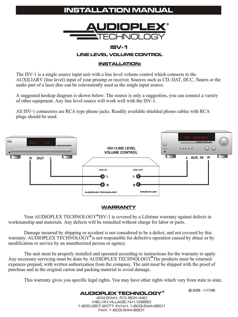
Audioplex ISV-1 User manual
Audioplex
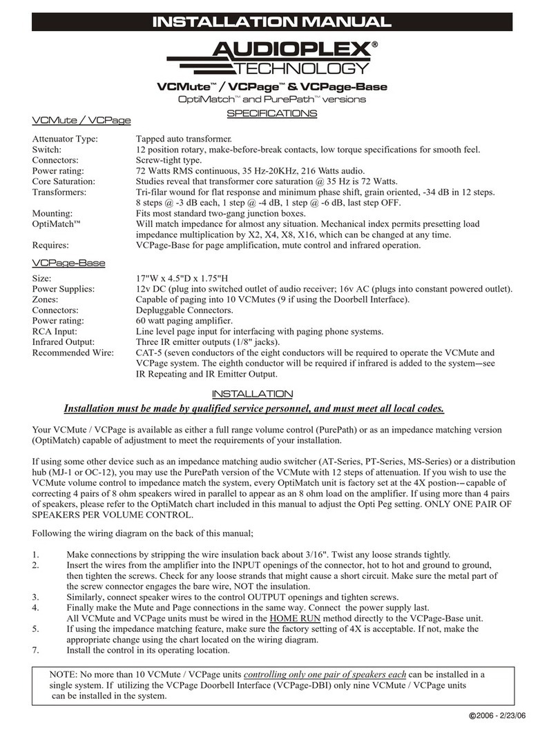
Audioplex VCMute User manual

Audioplex
Audioplex RCLL-1 User manual

Audioplex
Audioplex VC300 User manual

Audioplex
Audioplex VC75 OPTIMATCH User manual
Audioplex
Audioplex CSVC1550 User manual