AV-SMU70EN-A
Page 2 of 3
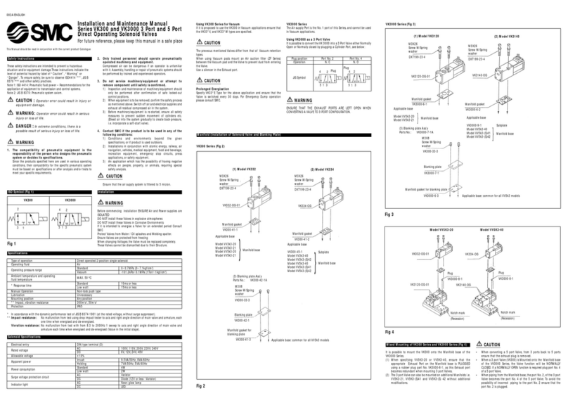
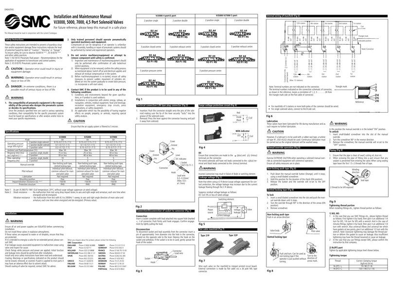
Ground nut
Tightening torque
1.65 to 2.5 N∙m
(Rating symbol)
Refer to the catalogue for DIN
connector part no.
Terminal screw
(3 locations)
Tightening torque
0.2 to 0.25 N∙m
0.2 to 0.25 N∙m
Holding screw
Tightening torque
0.4 N∙m
(Light mounting
location)
3 Installation - continued
regulator. With a standard regulator (AR10 to 60), the outlet side
pressure may not be released when this valve is exhausted.
Operation of solenoid valves on the outlet side
To operate solenoid valves mounted on this product’s outlet side (A port
side), make sure that the outlet side’s pressure (PA) has increased to
the pressure equal to the inlet side (PP).
Operation
The residual pressure release function of this product is for emergency
use only. Avoid using this valve in the same manner as ordinary 3 port
valves.
Using a lubricator
If mounting a lubricator, mount it on the inlet side (P port side) of this
product. If mounted on the outlet side (A port side), back flow of oil will
occur and may spurt out of the valve’s R port.
Operation for air blowing
This product cannot be operated for air blowing due to the mechanism
that switches the main valve to be fully open after the outlet side’s
pressure increases to approximately 1/2 of the inlet side.
Warning
Solenoid valve for 200, 220VAC
The AC solenoid valves with grommet have a built-in rectifier circuit in
the pilot section to operate the DC coil.
With 200V and 220 VAC pilot valves, this built-in rectifier generates
heat when energised. The surface may become hot depending on the
energised condition. To prevent burns, do not touch the solenoid valve.
3.2 Environment Warning
Do not use in an environment where corrosive gases, chemicals, sea
water or steam are present.
Do not use in an explosive atmosphere.
Do not expose to direct sunlight. Use a suitable protective cover.
Do not install in a location subject to vibration or impact in excess of
the product’s specifications.
Do not mount in a location exposed to radiant heat that would result
in temperatures in excess of the product’s specifications
Take suitable protective measures if water, oil or welding spatter is
likely to adhere to the valve.
Take measures to ensure air quality, such as by installing an
aftercooler, air dryer, or water separator. Compressed air that contains
a large amount of drainage can cause a malfunction of pneumatic
equipment such as valves. Therefore, take appropriate measures to
ensure air quality, such as by providing an aftercooler, air dryer, or
water separator.
Take suitable measures to prevent dust or noise if operating in an
environment generating dust or intrusive valve switching noise, by
providing a silencer in the R port.
Caution
Low temperature operation
Although the valve can be operated at temperature as low as 0°C,
measures should be taken to avoid solidifying or freezing drainage and
moisture.
3.3 Piping Caution
Before connecting piping make sure to clean up chips, cutting oil, dust
etc.
When installing piping or fittings, ensure sealant material does not
enter inside the port. When using seal tape, leave 1.5-2 thread ridges
exposed on the end of the pipe/fitting.
Refer to the instruction manual/operation manual during installation
and make sure to connect to the correct supply port, etc.
F.R.L module combination
When connecting to a modular F.R.L. unit (AC20 to 60), select one of
the spacers, included amongst the accessories. However, modular
combinations with AC40-06 are not possible.
3 Installation - continued
Furthermore, connect soft start-up valves to the outlet side of the F.R.L.
combination.
Inlet side piping conditions
The nominal size of the piping material’s or equipment’s bore should
be equal to or larger than the soft start-up valve’s port size. The
combined sonic conductance of the inlet side’s (P port side’s) piping or
equipment should be equal to or larger than the values below.
Combined sonic conductance
[dm3/(s·bar)]
When the piping is restricted or the supply pressure is insufficient, the
main valve will not switch and air leakage may occur from the R port.
Tighten fittings to the specified tightening torque.
Proper tightening torque (N▪m)
3.4 Lubrication Caution
The valve has been lubricated for life at the factory, and does not
require any further lubrication.
If a lubricant is used in the system, refer to catalogue for details.
Once lubricant is utilized within the system, since the original lubricant
applied within the product during manufacturing will be washed away,
please continue to supply lubrication to the system. Without continued
lubrication, malfunctions could occur. If turbine oil is used, refer to the
corresponding Material Safety Data Sheet (MSDS).
Lubrication amount
If a lubricant is applied excessively, it may accumulate inside the pilot
valve, causing malfunction or delayed response. Avoid using large
amount of lubricant. If it is not avoidable, use an external pilot type,
whereby supply air to the external pilot port contains no oil. This
prevents accumulation of oil inside the pilot valve.
3.5 Wiring Caution
When electric power is connected to a solenoid valve, make sure to
apply correct voltage. Incorrect voltage may cause malfunction or coil
damage.
Check the connections.
Check if the connections are correct after completing all wiring.
External force applied to lead wire
An excessive force to the lead wire may cause wire breakage. Take
appropriate measures to avoid applying a force of 30 N or more to the
lead wire.
Voltage leakage
Particularly when using a C-R element (surge voltage suppressor) to
protect the switching element, take note that leakage current will flow
through the C-R element, increasing leakage voltage.
AC coil is 8% or less of rated voltage.
DC coil is 3% or less of rated voltage.
3.6 Air supply Caution
Install air filters close to the valve on the upstream side.
Implement countermeasures by installing after-cooler or air dryer, or
water separator, etc.
3 Installation - continued
The compressed air containing a large amount of moisture may result in
a malfunction of the valve and other pneumatic equipment. Install an
after-cooler, air dryer or water separator or otherwise take an
appropriate measure.
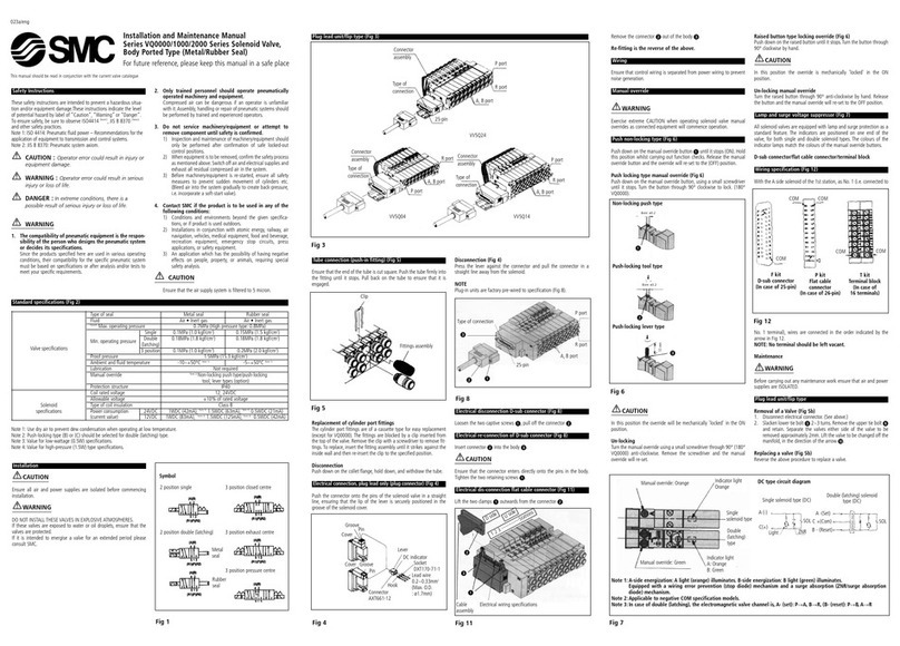
3.7 Surge voltage suppressor Caution
3.7.1 DC power supply
3.7.1.1 Grommet –standard type (with polarity)
With light/surge voltage suppressor (Z)
NOTE1: Connect correctly the lead wires to + (positive) and - (negative)
indications on the connector.
NOTE2: Solenoids, whose lead wires have been pre-wired: positive
side (+) is red and negative side (-) is black.
3.7.1.2 DIN Terminal
With light/surge voltage suppressor (DZ)
DIN terminal has no polarity.
3.7.2 AC power supply
3.7.2.1 Grommet
With light (GZ)
3.7.2.2 DIN Terminal
With light (DZ) and (YZ)
NOTE1: Surge voltage suppressor of varistor has residual voltage
corresponding to the protective element and rated voltage; therefore,
protect the controller side from the surge voltage. The residual voltage
of the diode is approximately 1V.
3.8 How to use DIN terminal
3.8.1 Construction
Type “Y”
Y type DIN connector is a DIN connector that confirms to the DIN pitch
8-mm standard.
Type “D”
D type DIN connector with 9.4 mm pitch between terminals is not
interchangeable with Y type connector.
To distinguish between “Y”and “D”type DIN connector, “Y”has “N”
listed at the end of voltage symbol. For connector parts without lights,
“N” is not indicated. Refer to the name plate to distinguish.
“Y” Dimensions are the same as “D”type DIN connector.
When exchanging the pilot valve assembly only, “V115K-□D-X400”
is interchangeable with “V115K-□Y-X400”. Do not replace “V111K-
□G-X400”with “V115-□D/□Y-X400”(DIN terminal), and vice versa.
3.8.2 Connection
1. Loosen the holding screw and pull the connector out of the solenoid
valve terminal block.
3 Installation - continued
2. After removing the holding screw, insert a flat head screwdriver, etc.
into the notch on the bottom of the terminal block and pry it open,
separating the terminal block and the housing.
3. Loosen the screw (slotted screws) on the terminal block. Insert the
lead cores wires into the terminals according to the connection
method, and secure the wires by re-tightening the terminal screw.
4. Secure the cord by tightening the gland nut.
Caution
When making connections, take note that using other than the
supported size (ø3.5 to ø7) heavy duty cord will not meet IP65
(enclosure) standards. Ensure to tighten the gland nut and holding
screw within their specified torque ranges.
3.8.3 Changing the entry direction
After separating the terminal block and housing, the cord entry can be
changed by attaching the housing in the desired direction (4 directions
at 90° intervals).
*When equipped with light, handle carefully to avoid damage to the light
with the lead wires in the cable.
NOTE: Plug in and pull out the connector vertically without tilting to one
side.
3.8.4 Compatible cable
Cable O.D.: ø3.5 to ø7
(Reference) 0.5mm2, 2-core or 3-core, equivalent to JIS C 3306
3.8.5 DIN Connector part numbers
3.8.6 Circuit Diagram with light
