17
Initial start-up and functions
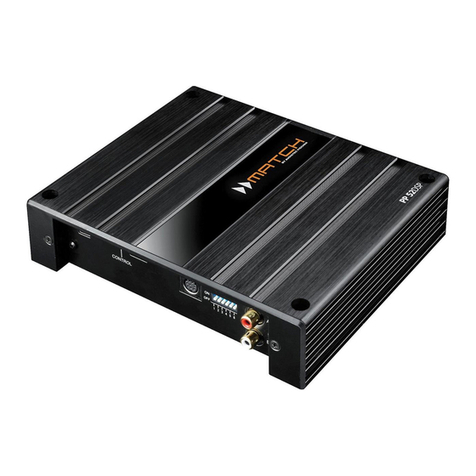
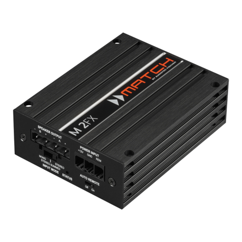
1Subwoofer Output
This output provides for the connection of a passive
Plug & Play subwoofer like the MATCH PP 7E-D
RU336'7KHFDUVSHFL¿FVHWXSVRQRXUZHEVLWH
always mention the recommended subwoofer type.
When using a subwoofer, we strongly recommend
to connect the PP 62DSP directly to a 12 Volt
source. Refer to connection instructions in section
3b, page 21.
2Input Sensitivity
This potentiometer allows to increase the input sen-
VLWLYLW\RIWKHKLJKOHYHOLQSXWVXSWRPD[G%7KLV
function should only be used if the signal source has
a low output volume. This is not a volume control,
LWV RQO\ IRU DGMXVWLQJ WKH DPSOL¿HU JDLQ 7KH FRQ-
trol range of the highlevel input goes from 11 Volts
PD[&&:SRVLWLRQWR9ROWVPD[&:SRVLWLRQ
Please note:7KHLQSXWVHQVLWLYLW\H[ZRUNVLVVHWWR
9ROWVPD[&&:SRVLWLRQ
3Clipping LED
This LED lights up red if one of the four highlevel
inputs is overdriven. The LED has no function when
an input signal is applied to the MEC module or if
DFDUVSHFL¿FVRXQGVHWXSLVXVHG$VVRRQDVWKH
LED lights up, the input sensitivity should be re-
duced by turning the Input Sensitivity knob count-
er-clockwise until the LED goes out.
4System Connector
Please use this terminal only in combination with
the cable harness that is included in the delivery of
WKHDPSOL¿HURUIURPWKH0$7&+DFFHVVRULHVSUR-
gram. Never ever use any other harnesses to con-
nect the MATCH PP 62DSP to your car radio.
Caution: The use of other harnesses than the one
WKDWLVVXSSOLHGZLWKWKHDPSOL¿HUPD\FDXVHVHYHUH
KDUPWRWKHDPSOL¿HU\RXUFDUUDGLRKHDGXQLWDQG
your loudspeakers. In any case the warranty will be
void!
5USB Input
Connect your personal computer to the PP 62DSP
using the provided USB cable. The required
'63 3&7RRO VRIWZDUH WR FRQ¿JXUH WKLV DPSOL¿HU
can be downloaded from the Audiotec Fischer web-
site ZZZDXGLRWHF¿VFKHUFRP.
Please note: It is not possible to connect any USB
storage devices.
6Control pushbutton
The Control Pushbutton allows the user to toggle
between the two memory areas. Setups with the
H[WHQVLRQ³DI´RU³DF´ZLOOEHDXWRPDWLFDOO\ZULWWHQ
WRWKH¿UVWVWRUDJHSRVLWLRQZKHUHDVVHWXSVZLWKWKH
H[WHQVLRQ³DI´RU³DF´ZLOOEHZULWWHQWRWKHVHFRQG
storage position. To switch between the setups, the
EXWWRQKDVWREHSUHVVHGDQGKHOGIRUDSSUR[VHF-
RQG6ZLWFKLQJLVLQGLFDWHGE\DVLQJXODUUHGÀDVKRI
the Status LED. Pressing the button for 5 seconds
completely erases the internal memory. This is in-
GLFDWHGE\DFRQVWDQWÀDVKLQJRIWKHStatus LED.
Attention: After erasing the setups from memory
the PP 62DSP will not reproduce any audio output
until a new setup is loaded.
7Status LED
The Status LED indicates the operation mode of the
DPSOL¿HU*UHHQPHDQVWKDWVHWXSDILVORDGHG
orange means that setup 2 (af2) is loaded.
If it lights up red constantly, the undervoltage pro-
WHFWLRQ LV DFWLYH$ ÀDVKLQJ UHG OLJKW LQGLFDWHV WKDW
no setup is loaded. In that case please load a new
setup via the DSP PC-Tool software or the internal
MicroSD card reader.
8MicroSD card reader
The MicroSD card reader allows the user to easily
FRS\FDUVSHFL¿FVHWXSVWRWKHDPSOL¿HU )LUVW \RX
have to download a sound setup (e.g. from our web-
site ZZZDXGLRWHF¿VFKHUFRP) and copy it to a
MicroSD card. After having inserted the MicroSD
FDUG LQWR WKH FDUG VORW RI WKH 33 '63 WKH ¿OH
will be automatically copied to the internal memo-
U\ RI WKH DPSOL¿HU :KLOH WKH FRS\ LV LQ SURJUHVV
the Status LED ÀDVKHV UHG ,W FKDQJHV WR JUHHQ
RU RUDQJH RQFH WKH SURFHVV LV ¿QLVKHG 1RZ WKH
MicroSD card can be safely removed.
Attention: Never remove the MicroSD card while
the copy process is in progress!
The PP 62DSP can manage two different set-
XS ¿OHV 7KH\ DUH PDUNHG ZLWK WKH ¿OH H[WHQVLRQV
³DI´³DF´VWRUHGLQPHPRU\RIWKHDPSOL¿HURU
³DI´³DF´VWRUHGLQPHPRU\RIWKHDPSOL¿HU
Please note: Do not store more than one “af1”
RU ³DF´ DQG RQH ³DI´ RU ³DF´ VHWXS ¿OH RQ WKH
MicroSD card at a time.


