Audiovox Prestige Platinum Plus APS-510C User manual

128-8806b
1 of 12
Page1
Model APS-510C
InstallationManual
Remote Control Vehicle
Security System
Rev B: New Format
PATENTED: www.voxxintl.com/company/patents
Table Of Contents:
BeforeYouBegin Page 2
Wire Harnesses Quick View Page 3
MountingOf TheMajorComponents Page 4
8PinPower Connector Page 5 - 6
11PinAccessoryInput/OutputConnector Page 6
2 Pin LED / Valet Connectors Page 8
3 Pin Door Lock/Unlock Connector & Wiring Page 8 - 10
4PinUpgradeTelematic Module Page 10
Completingthe Installation Page 10
DomeDelayLearningProceedure Page 10
AdjustingTheShock Sensor Page 10
WireDressingandOperationExplanation Page 10
ProgrammingTransmitters Page 11
ProgrammingAlarmFeatureBank2 Page 11
CircuitWiringLayout Page 12

128-8806b
2 of 12
Page2
Before You Begin
PROFESSIONAL INSTALLATION IS
STRONGLYRECOMMENDED
Rolldownwindow to avoidlockingthekeysin the vehicleduringinstallation.
Avoidmountingcomponents or routing wiresnearhotsurfacesor near moving
partslikethesteeringwheel as it may prevent proper operation of the vehicle.
Tapeorloomwiresunderthehoodanddashforprotectionaswellappearance.
Usegrommets whenroutingwiresthroughmetal surfacestopreventchafing
andshorting.
UseaDigitalMultiMeterfortestingandverifyingcircuits. DONOTUSEA
"TEST LIGHT" OR "COMPUTER SAFE PROBE" as these can set off air bags
ordamagesensitivevehiclecomputers and electronics.
For technical support go to www.prestigecarsecurity.com
or call 1 800 225 6074
This device complies with FCC Rules Part 15 Operation is subject to the following two conditions
(1) This device may not cause harmful interference and
(2) This device must accept any interference that may be received, including interference that
may cause undesired operation.
NOTE:The manufacturer is not responsible for any radio or TV interference caused by unautho-
rized modifications to this equipment. Such modifications could void the user’s authority to
operate the equipment

128-8806b
3 of 12
Page3
1
3 Pin Door Lock Output Harness Part #1122906
2
3
11 Pin Main Wiring Harness Part # 1122916
1
2
3
4
5
6
7
8
9
10
11
1
2
3
8 Pin Power Input / Output Harness Part #1122393
4
5
Red/White +12 Volt ModuleInput
Orange GroundOutputWhileArmed(-) 300mA
White/Black +12VoltsSiren Output
6
7
8
Green/White IlluminationEntryOutput(-)300mA
DarkBlue Channel3Trunk Output(-)300mA
Black ChassisGround
White (+)Parking LightOutput15A Max
Red (+)12VoltInputParking Lts & Module
Red Neg.Lock/Pos.Unlock 300mAMax.
Red/Black Neg.2ndUnlock Output (-) 300mA
Green Pos.Lock/Neg.Unlock 300mAMax.
Green /Black Channel 4 Output (-) 300mA
Orange/White Gnd. Output When Disarmed (-) 300mA
Purple Pos. Door Trigger Input
White/Blue Programmable Headlight Out (-) 300mA
Blue / Black Alternate Channel 3 Output (-) 300mA
Black /White Horn Output (-) 300mA
DarkGreen NegativeHood/TrunkTriggerInput
Brown Neg. Door Trigger Input
Yellow IgnitionInput Switched +12 Volts
Lt.Green Add. Neg. Trigger Input
Lt.Blue/ Green Channel 5 Output (-) 300mA

128-8806b
4 of 12
Page4
MOUNTINGOF THEMAJOR COMPONENTS
Control Module: Part # 1362302
Selectamounting location insidethe passenger compartment(up behind thedash) and secureusingthe
two screws provided. The control module can also be secured in place using cable ties.
Do Not mountthe controlmodulein theenginecompartment,as itisnot waterproof.Youshouldalso avoid
mounting the unit directly onto factory installed electronic components.These components may
causeRFinterference, which can resultinpoor transmitter rangeorintermittent operation.
Siren: Part # AS9903
Selecta mounting locationin the enginecompartment that iswell protected fromaccess below thevehicle.
Avoidareas nearhighheat components ormovingpartswithin the enginecompartment.To prevent water
retention, the flared end of the siren must be pointed downward when mounted. Mount the siren to the
selectedlocationusing the screws andbracketprovided.
Hood or Trunk Pin Switch: (Optional) Part#1363699
An optional pin switch should be used for protecting the hood or trunk (or hatchback ) of the vehicle. The
switch must always be mounted to a grounded, metal surface of the vehicle. It is important to select a
location where water cannot flow or collect, and to avoid all drip gutters on hood and trunk fender walls.
Chooselocationsthat areprotectedby rubber gasketswhen the hoodortrunk lidisclosed. The pin switch
can be mounted using an optional bracket or can be directly mounted by drilling a ¼ " diameter mounting
hole. Keep in mind that when properly mounted, the plunger of the pin switch should depress at least ¼ "
when the hood or trunk lid is closed.
Pushbutton LED Combination Switch: Part # PBLED
Selectamounting location knownandaccessible to theoperatorof the vehicle. A dashboardplugor front
dashboardpanelis desirablebecausethe pushbutton LEDassemblyneeds the LEDtobe visible fromthe
outsideof thevehicle. Itwillbeusedforvaletmodes,programmingfeatures,programmingtransmitters,and
for overriding the system when the transmitter is not functioning. Inspect behind the chosen location to
insurethat adequate clearanceis allowed forthe bodyofthe switch,andalso thatthedrill willnotpenetrate
any existing factory wiring or fluid lines. Drill a 5/16" or 8mm hole in the desired location and mount the
switchbypassing the connectors, one atatime, through the panel fromthefront side and pressing onthe
bezel until the switch is fully seated.
ShockSensor: Part # AS9492a
Selecta solidmountingsurfaceforthe shocksensor onthefirewall insidethe passengercompartment, and
mountthe sensor usingthe two screwsprovided. The shocksensor can alsobe secured toany fixed brace
behindthedash usingtiestraps. Whichevermountingmethod is selected,makecertain thatthesensitivity
adjustment is accessible for use later in the installation.
STARTERINHIBIT RELAY: Part # 1363731
Select a mounting location within 12" of the ignition switch's low current start solenoid wire. Secure the relay to an
existing harness in the chosen location using a cable tie around the relay's wiring harness.
Wire the relay as per the diagram found later in this manual.
CAUTION! Do not wire tie the metal bracket to an existing wiring harness as vibration may cause
chaffingandshorting damaging thefactorywiring. Ifan existing harnessisnot available then
secure the relay's metal mounting tab to an under dash metal brace with a #8 self tapping
sheet metal screw. Wire the relay as per the diagram found later in this manual.

128-8806b
5 of 12
Page5
WIRING THE SYSTEM
Large 8 Pin Power Connector:
Red/White (5 Amp) & Red Fused (15 Amp) Wires : + 12 VDC Constant Battery Source
This wire controls the sensitivity of the voltage sensing circuit, which detects the turning on of an interior
lightwhen adooris opened.It willalso detecttheswitching onof parkingorheadlamps,andin manycases
willtriggerthealarm when a thermostatically controlled electronic radiatorcoolingfanswitches on.
When installing this system into vehicles with electronic "after fans " it is recommended you disable the
voltagesensecircuit.
In voltage sensing applications, the closer to the battery that the red wire is connected, the less sensitive
thevoltagesense circuitrywillbe. Movingthisconnection point tothefuse panelwillincrease the sensitiv-
ity,andconnecting to thecourtesylamp fuse inthevehicle will provide maximumsensitivityof the voltage
sense circuit. Be certain to set selectable feature # 7 to 1 chirp, Voltage Sense On.
When hardwiring the control module to pin switches at all entry points, the voltage sense circuit must be
disabled.
Orange Wire: 300 mAGround Output WhenArmed
This wire is provided to control the starter cut relay. Connect the orange wire to terminal 86 of the relay.
Connect relay terminal 85 to an ignition wire in the vehicle that is live when the key is in the on and crank
positionsand offwhenthe keyis intheoff position. (Thisiswhere theyellow wirefromthe alarmshould be
connected).
Cutthe lowcurrent startersolenoidwireinthevehicle,andconnectone sideof thecut wiretorelayterminal
87A. Connect the other side of the cut wire to relay terminal 30.
Note: This is a normally closed starter cut arrangement and when power is removed from the security
system,thestarter disablefeaturewill not operate,allowing the vehicletostart.Audiovoxdoesnot
recommend usingthe Orangewire tointerrupt anythingbut thestarting circuit ofthevehicle.
Green w/ White trace Wire: Entry Illumination Ground Output
Thiswireprovidesa30secondgroundoutput(300mAMax) whenevertheremoteisusedtodisarmthealarmorto
unlock the doors and provides a continuous pulsed output whenever the alarm is triggered. This wire should be
connectedtoanexternalrelay andwired tothevehiclesinteriorentrylightingwhenevertheoptionalInteriorIllumina-
tioncircuit isdesired. SeeWiring Diagramfor details.
Dark Blue Wire: Delayed300 mA PulsedOutput/ Channel 3
ThedarkbluewirepulsestogroundviaanindependentRFchannelfromthekeychaintransmitter.Thisisatransis-
torized,lowcurrentoutput,andshouldonlybeusedtodriveanexternalrelaycoil.
CAUTION: Connectingthe dark bluewireto thehighcurrent switched outputoftrunk releasecircuits,and some
remotestarttriggerinputs,willdamagethecontrolmodule. Inthesecases,connectthedarkbluewire
to terminal 86 of anAutomotive 30AMP relay, terminal 85 to +12 Volts, and wire the remaining relay
contactstoperformtheselectedfunctionofchannel3.
White w/ Black Trace Wire: Positive Output to Siren
Routethiswirethrougharubbergrommetinthefirewall,andtothesirenlocation.
Connectthewhite / blackwireto the positive wireofthe siren. Securetheblack ground wire ofthesiren to chassis
ground.

128-8806b
6 of 12
Page6
Black Wire: Chassis Ground
Connectthiswire to a solid,metalpart of the vehicle’schassis.Do not confuse thiswirewiththe thin black antenna
wirethatexitsthecontrolmoduleindependently.
White Wire: + 12 VDC Pulsed Parking Light Output (15Amp Max)
This wire is provided to flash the vehicle’s parking lights. Connect the white wire to the positive side of one of the
vehicle’sparkinglights.
WiringThe11AccessoryInput/Output Connector:
Dark Green w/ Black Trace Wire: Latching Output / Channel 4
Thegreenw/blacktracewirelatchestogroundviaanindependentRFchannelfromthekeychaintransmitter.Thisis
atransistorized,lowcurrent( 300mA)output,and shouldonlybeusedtodriveanexternalrelaycoil.
This wire provides an immediate ground signal, and stays at ground for as long as the button(s) on the keychain
transmitterremainspressed.
CAUTION! Connecting the dark green w/ black trace wire to the high current switched output of trunk
release circuits will damage the control module.
Connectthedarkgreenw/blacktracewiretoterminal86oftheAS9256relay(oranequivalent30Ampautomotive
relay),andwiretheremainingrelaycontactstoperformtheselectedfunctionofchannel4.
Dark Blue w/Black Trace Wire:AlternateChannel 3 Output(Dbl. Push Required)
Thiswireiscontrolledfromthetransmitterbuttonprogrammedtothereceiver'schannel3. Bydoublepressingthisthe
transmitterbutton,thisoutputwillbecomeactivefor1second. Thisisatransistorized,low current(300mA)output,
designedtoprovideanoutputonlywhenthetransmitterisintentionallyoperated,suchasisthecasewithremotestart
addonmodules. If you require more than300mAdrive from this output, youmust drivean external relay coil, and
arrangetherelayscontactstopreformthespecifiedfunction.
Note: Pressingthetransmitterbutton,thenimmediatelypressingandholdingitwillcausethisoutputtobeactiveas
longas the transmitterbutton is depressed.
Black w/ White Trace Wire: 300 mAHorn Output
The black w/ white trace wire is provided to beep the vehicle’s horn. This is a transistorized low current output, and
shouldonlybeconnectedtothelowcurrentgroundoutputfromthevehicle’shornswitch.
Ifthe vehicleuses a+12VDChornswitch,thenconnecttheblackw/whitetrace wireto terminal86 oftheAS 9256
relay(oranequivalent30Ampautomotiverelay),andconnectrelayterminal85toafused+12VDCbatterysource.
Connect relay terminal 87 to the vehicle’s horn switch output, and connect relay terminal 30 to a fused + 12 VDC
batterysource.
Orange w/ White Trace Wire: 300 mAGround Output When Disarmed - N. O. Starter Disable
( Optional Relay Required ).
Thiswireisprovidedtocontrolthestartercutrelay.Connecttheorangew/whitewiretoterminal86oftherelay.Connect
relayterminal85toanignitionwireinthevehiclethatislivewhenthekeyisintheonandcrankpositions,andoffwhen
thekey isinthe offposition. (Thisis wherethe yellowwirefrom thealarm shouldbeconnected ).
Cut the low current starter solenoid wire in the vehicle, and connect one side of the cut wire to relay terminal 87.
Connectthe othersideofthecutwiretorelayterminal 30.
Note: Thisisanormallyopenedstartercutarrangement,andwhenpowerisremovedfromthesecuritysystem,the
starter disable feature will remain operational, and the vehicle will not start.Audiovox does not recommend
usingtheOrangew/Whitetracewire tointerruptanythingbutthe startingcircuitofthevehicle.

128-8806b
7 of 12
Page7
Dark Green Wire: ( - ) Instant Trigger Zone
Thisis aninstanton groundtrigger wire.Itmust beconnected totheoptional previouslyinstalledhoodand
trunk pin switches when used.
Brown Wire: - Door Trigger
If the vehicle’s courtesy light switches have a ( - ) ground output when the door is opened (GM and most
Imports), you must connect this wire to the negative output from one of the door switches.
WARNING: Do not use the brown wire if the vehicle has + 12 volt output type door switches.
(SeePurpleWire). Note for vehicleswithinterior delay lightingseeprogramming under title
CompletingThe Installation".
Purple Wire: + Door Trigger
If the vehicle’s door courtesy light switches have a + 12 volt output when the door is opened (most Fords
and some Imports), you must connect this wire to the positive output from one of the door switches.
WARNING: Do not use the purple wire if the vehicle has ground output type door switches.
(seeBrown Wire ). Noteforvehicles with interior delaylightingsee programming undertitle
"CompletingThe Installation".
Yellow Wire: + 12 VDC Ignition Source
Connect this wire to a source that is live when the key is in the on and crank positions. Be sure that this
source is off when the key is in the off position.
White w/ Blue Trace Wire: Low Current (-) Ground Headlight Output
The White w/ Blue Trace wire is provided to operate the optional headlamp illumination feature of the
system. This is a low current (300mA) output and must be connected to an external relay to control the
high current switching circuit of the vehicle's headlamps. To use this option, Connect the White /w Blue
Trace wire to terminal # 86 of a P&B VF45F11 relay or equivalent. ConnectTerminals #85 and # 30 to a
fused + 12 Volts source with a current capability equal to or in excess of the factory headlamp fuse.
Connect terminal # 87 of the relay to the switched + 12 volt wire feeding the vehicle's headlamp circuit.
NOTE: For groundswitchedheadlamp circuits, Connect theWhite/w Blue Trace wiretoterminal # 86
of a P&B VF45F11 relay or equivalent. Connect Terminal #85 to a fused + 12 Volts source.
Connectterminal #30to acleanchassis ground. Connectterminal #87to theground switched
headlampcontrolwire inthevehicle.
Light Green Wire: (-) Instant Trigger Zone 1
This is a instant on ground trigger input intended for the connection of optional triggering devices. The
ground trigger output wire of motion detectors, microwave detectors, or glass break detectors, can be
connectedtothisLightGreen trigger input wire.
Light Blue/Green Wire: Delayed 300 mA Pulsed Output / Channel 5
Thelightblue/green wire pulses togroundvia an independentRFchannel from the keychaintransmitter.
This is a transistorized, low current output, and should only be used to drive an external relay coil.

128-8806b
8 of 12
Page8
WARNING: Connecting the light blue/green to the high current switched output of trunk release
circuits, some remote start trigger inputs, will damage the control module.
Connect the light blue/green to terminal 86 of a 30 A automotive relay, connect terminal 85
to a + 12 volt source, and wire the remaining relay contacts to perform the selected
function of channel 5.
2 Pin White Connector: DASH MOUNTED LED.
Route the red and blue wires in the 2 pin white connector from the LED to the control module and plug it into the
mating white connector on the side of the module.
2 Pin Blue Connector: PUSHBUTTONVALETSWITCH
Route the black and gray wires in the two pin blue connector from the pushbutton valet switch to the control module
and plug it into the mating connector on the side of the module.
4 Pin White Connector: SHOCK SENSOR PART # 1122591
Route the red, black, blue, and green wires in the 4 pin white connector from the shock sensor to the control
module, and plug one end into the shock sensor, and the other end into the mating white connector on the side of
the module.
Red, Green, & Red / Black 3 Pin White Connector: Door Lock Outputs PART# 1122906
The Red and Green wires will provide either a pulsed ground output to the factory door lock control relay, or a
pulsed + 12 volt output to the factory door lock control relay. In either case, the maximum current draw through
these outputs must not exceed 300 mA. The Red w/Black trace wire will provide a pulsed ground only, and will only
provide an output when the unlock button of the transmitter is pressed a second time after a first unlock command
was issued. This is used for second step unlock or all doors unlock in a two step circuit. In this arrangement, Red,
or Green is used to control the drivers door unlock relay and the Red/Black will be used to control unlock of all other
doors.
3 Wire Ground Switched Single Step Door Locks
In this application, the red wire provides a ground pulse during arming, or the pulsed ground lock output. Connect
the red wire to the wire that provides a low current ground signal from the factory door lock switch to the factory door
unlock control relay.
The green wire provides a ground pulse during disarming, or the pulsed ground unlock output. Connect the
green wire to the wire that provides a low current ground signal from the factory door unlock switch to the factory
door unlock control relay.
Red/Black Not Used.
3 Wire Ground Switched 2 Step Door Locks
In this application, the red wire provides a ground pulse during arming or locking, connect the red wire to the wire
that provides a low current ground signal from the factory door lock switch to the factory door lock control relay.
The green wire provides the first ground pulse during disarming or unlocking, connect this wire to the drivers
door unlock relay that requires a low current ground signal to unlock only the drivers door.
If the vehicle does not have a separate drivers door relay, one will have to be added. Locate the drivers door unlock
motor wire and cut it at a convenient location to allow wiring of an optional relay.
Connect the door side of the cut wire to terminal 30 of the optional relay added.
Connect the vehicle side of the cut wire to terminal 87a of the optional relay added.
Connect the green wire of the 3 pin harness to terminal 86 of the optional relay added.
Connect terminal 85 of the optional relay added to a fused constant + 12 volt source.
Most vehicles door lock/unlock motor legs rest at ground and switch +12 volts to the door lock/unlock
motor legs for operation, if this is the case in the vehicle you are working on, connect the remaining
terminal, 87, to a fused + 12 volt source.
128-8806b
9 of 12
Page9
In the rare instance that the vehicle door lock/unlock motor legs rest at + 12 volts and switches ground to the door
lock/unlock motors, connect he remaining terminal, 87, to chassis ground.
The Red/Black wire provides a pulse ground output when the unlock button of the transmitter is pressed a second
time after disarming.
Connect the Red/Black wire to the wire that provides a low current ground signal from the factory door unlock switch
to the factory door lock control relay.
3 Wire Positive Switched Door Locks
In this application, the red wire provides a positive pulse during disarming or unlocking, connect the red wire to the
wire that provides a low current positive signal from the factory door unlock switch to the factory door unlock control
relay.
The green wire provides a positive pulse during arming or locking, connect the green wire to the wire that provides
a low current positive signal from the factory door lock switch to the factory door lock control relay.
3 Wire Positive Switched 2 Step Door Locks
The green wire provides a positive pulse during arming or locking, connect the green wire to the wire that provides
a low current positive signal from the factory door lock switch to the factory door lock control relay.
The red wire provides a positive pulse during disarming or unlocking, connect this wire to the drivers door unlock
relay that requires a low current positive signal to unlock only the drivers door.
If the vehicle does not have a separate drivers door relay, one will have to be added. Locate the drivers door unlock
motor wire and cut it at a convenient location to allow wiring of an optional relay.
Connect the door side of the cut wire to terminal 30 of the optional relay added.
Connect the vehicle side of the cut wire to terminal 87a of the optional relay added.
Connect the red wire of the 3 pin harness to terminal 86 of the optional relay added.
Connect terminal 85 of the optional relay added to chassis ground.
Most vehicles door lock/unlock motor legs rest at ground, and switch +12 volts to the door lock/unlock motor legs
for operation, if this is the case in the vehicle you are working on, connect the remaining terminal, 87, to a fused
+ 12 volt source.
In the rare instance that the vehicle door lock/unlock motor legs rest at + 12 volts and switches ground to the door
lock/unlock motors, connect he remaining terminal, 87, to chassis ground.
The Red/Black wire provides a pulse ground output when the unlock button of the transmitter is pressed a second
time after disarming. Because the vehicle you are working on requires a positive pulse from the factory door lock
switch to the factory door lock control relay, you will have to add a relay to invert the output polarity of this wire.
Connect the Red/Black wire to terminal 86 of the optional added relay.
Connect terminal 85 & 87 to a fuse + 12 volt source.
Connect terminal 30 to the low current door unlock wire from the factory door switch to the door unlock control relay.
Resistive Circuits, As Well As 4 Wire Polarity Reversal and
5 WireAlternating 12 Volt Door Lock Control Circuits
These applications require the use of additional components which may include relays, fixed resistors, or for
convenience, theAS 9159a Door Lock Interface. Refer to theAUDIOVOX Door Lock Wiring Supplement and or the
Audiovox fax back service for information on your particular vehicle for properly connecting to these types of circuits.
4 Pin Upgrade Telematic Module:
Red = + 5 Volts
Black = Ground
White = Data TX
Yellow = Data RX
Connect the 4 pin harness found in the Telematic one way module kit to the mating port on the telematic module
and the other side to the connector on the alarm or keyless entry module.

128-8806b
10 of 12
Page10
NOTE: If using the TWO WAYTelematic module, only Ground, TX, and RX are used on this port, the
+ 12volt supply for the two way module must be sourced separately or the unit will not operate.
COMPLETINGTHE INSTALLATION
NOTE: This unit has the ability to learn the dome light delay time, up to 60 seconds. If the vehicle has
delay interior lights, and you wish to avoid three chirp, defect zone, indication normally
associated with this type of interior light, we suggest you learn the interior light delay.
TO LEARN THE DOME LIGHT ENTRYDELAY START WITHALL DOORS CLOSED:
(1) Use the transmitter to Lock / Unlock / Lock / Unlock / Lock / Unlock / Lock, the system.
The LED turns on solid to confirm the system entered the learn mode.
(2) Immediately open and close the door of the vehicle to initiate the dome delay.
Theunitwill monitorthedoor triggerinputPositive, (Purple),andNegative, (Brown)whenactive.
When the dome light turns off, the unit will add 2 seconds then exit the learn mode.
(3) The LED will begin flashing theArmed indication indicating the unit has exited the learn mode
andisarmed.
Antenna Wire:
Be sure to extend the thin black antenna wire to it’s full length, and cable tie into place where it cannot be
damaged.Avoidwrappingthiswire aroundmajor,highcurrent wirelooms.
Adjusting the Shock Sensor:
If used, the sensitivity of the pre - detect circuit is automatically set 30% less sensitive than the full trigger
circuit.
Usinga smallscrewdriver, gentlyturn theadjustmentscrew fullycounterclockwise. (DONOTover turnthis
screw. Maximum rotation for this adjustment is 270°). Close the hood and trunk lids, and arm the alarm.
Wait6seconds fortheaccessories trigger zonetostabilize, thenfirmlystrike the rearbumperwith theside
ofaclosed fist considering theamountof force required tobreaka window.
WARNING ! Never perform this test on the vehicle’s glass, as you may break the window.
Turn the adjustment screw clockwise (increasing sensitivity) about ¼ turn and re-test. Re-
peat this procedure until the alarm sounds. Ultimately, one firm strike to the rear bumper will
cause the alarm to emit pre-detect warning tones.
CAUTION: Setting the sensitivity too high can cause false alarms due to noise vibrations from passing
trucksandheavyequipment.Todecreasesensitivity,turntheadjustment screwcounter
clockwise.
Wire Dressing:
Always wrap the alarm wires in convoluted tubing, or with a spiral wrap of electrical tape. Secure these
looms along the routing using cable ties. This will ensure that the alarm wires are not damaged by falling
ontohotor sharp movingsurfacesin the vehicle.
Operation:
Take a few moments to check off the appropriate option boxes in the owner’s manual, and to fully explain
the operation of the system to your customer.

128-8806b
11 of 12
Page11
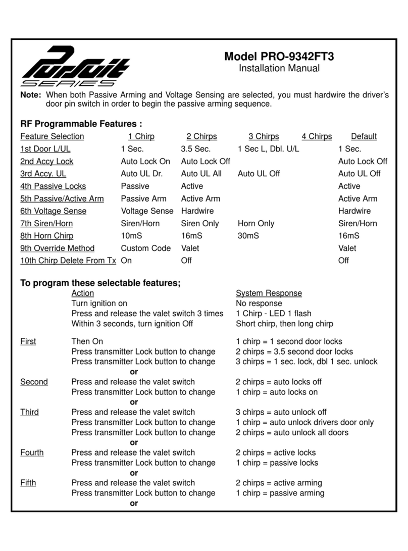
SELECTABLEFEATURES
Programmable Features :
Feature Selection 1 Chirp 2 Chirps 3 Chirps 4 Chirps 5 Chirps Default
1st Door L/UL 1 Sec. 3.5 Sec. 1 S L, Dbl.U/L 350mS UL/1SL 1 Sec.
2nd Accy Lock Auto Lock On Auto Lock Off Auto Lock Off
3rd Accy. UL Auto UL Dr Auto UL All Auto UL Off Auto UL Off
4th Headlights On Arm On Disarm On Both Off Both
5th Passive Locks Passive Active Active
6th Passive/Active Arm Passive Arm Active Arm Active Arm
7th Voltage Sense Voltage Sense Hardwire Hardwire
8th Siren/Horn Siren/Horn Siren Only Horn Only Siren/Horn
9th Horn Chirp 10mS 16mS 30mS 40mS 50mS 16mS
10th Override Method Custom Code Valet Valet
11th Two Step Unlock On Off Off
12th Chirp Delete From Tx On Off Off
PROGRAMMINGBANK1(TRANSMITTERS):
1) Turn the ignition key to the on position.
2) Press and release the valet/programming switch 3 times (Siren Chirps).
3 Press the Lock Button of each transmitter you want programmed until you hear a chirp from the horn or siren.
4) Turn the ignition switch off.
The above action programs the Lock, Unlock, Start/Trunk, and Option 1 buttons of the system. For additional
channel programming see transmitter programming guide found within the literature bag packaged with this kit.
PROGRAMMINGBANK 2(ALARMFEATURES):
You can enter bank 2 from bank 1 by turning the ignition key off then on from step 4 of Bank 1.
(Siren Short then Long Chirp), or You can also go right to bank 2 by:
1) Turn the ignition key to the on position.
2) Press and release the valet/programming switch 3 times (Siren Chirps).
3) Turn the ignition key off then on. (Siren Short Then long Chirp)
4) Press the pushbutton switch once to advance to feature 1, twice to advance to feature 2, etc,,,then use the lock
button of the transmitter to select the feature setting.
Example to set passive arming:
1) Turn the ignition key to the on position.
2) Press and release the valet/programming switch 3 times (Siren Chirps).
3) Turn the ignition key off then on. (Siren Short Then long Chirp)
4) Press the pushbutton switch six times to advance to features 6, Pass/Act Arm, then use the lock button of the
transmitter to select two chirps "Passive Arm".
5)Toexit the programmingmode, turn theignitionkey off. The programmodeis automaticallyexitedwhen
there is no activity on the pushbutton switch or the transmitter lock button.

128-8806b
12 of 12
Page12
For technical support go to www.prestigecarsecurity.com or call 1 800 225 6074.
© 2013 Audiovox Electronics Corp., Hauppauge, N.Y. 11788 128-8806b
Other manuals for Prestige Platinum Plus APS-510C
1
Table of contents
Other Audiovox Security System manuals

Audiovox
Audiovox Prestige 128-8614 User manual

Audiovox
Audiovox AA-930 User manual

Audiovox
Audiovox Prestige Platinum APS-510C User manual

Audiovox
Audiovox PRO-9342FT3 User manual

Audiovox
Audiovox AXT-800 User manual

Audiovox
Audiovox PRO-9642a Pursuit Series User manual

Audiovox
Audiovox Prestige Platinum Plus APS-786T User manual

Audiovox
Audiovox Pursuit PRO-9649N User manual

Audiovox
Audiovox Prestige Platinum Plus APS-510C User manual

Audiovox
Audiovox PRO-9342FT3WOS2 User manual