AURES YUNO-151 User manual

User Manual
POS System series
YUNO-151
/ YUNO-151K
and
YUNO-156 / YUNO-156-50KH
Touch Monitor series
YUNO-151TM / YUNO-156TM
i
Copyrights
© 2015 All rights reserved. The information in this
document is subject to change without prior notice in
order to improve reliability, design and function and
does not represent a commitment on the part of the
manufacturer.
This document contains proprietary information
protected by copyright. All rights are reserved. No
part of this manual may be reproduced by any
mechanical, electronic, or other means in any form
without prior written permission of the manufacturer.
All trademarks are property of their respective owners
Liability Disclaimer
In no event will the manufacturer be liable for direct,
indirect, special, incidental, or consequential
damages arising out of the use or inability to use the
product or documentation, even if advised of the
possibility of such damages.
Regulatory Information
FCC Notice
This equipment has been tested and found to comply
with the limits for a Class A digital device, pursuant to
Part 15 of the Federal Communications Commission
(FCC) Rules. These limits are designed to provide
reasonable protection against harmful interference in
a residential installation. This equipment generates,
uses, and can radiate radio frequency energy and, if
not installed and used in accordance with the
instructions, may cause harmful interference to radio
communications. However, there is no guarantee that
interference will not occur in a particular installation. If
this equipment does cause harmful interference to
radio or television reception, which can be
determined by turning the equipment off and on, the
user is encouraged to try to correct the interference
by one or more of the following measures:
• Increase the separation between the equipment and
the receiver.
• Connect the equipment into an outlet on a circuit
different from that to which the receiver is connected.
• Consult the dealer or an experienced radio or
television technician for help.
NOTE: THE MANUFACTURER IS NOT
RESPONSIBLE FOR ANY RADIO OR TV
INTERFERENCE CAUSED BY UNAUTHORIZED
MODIFICATIONS TO THIS DEVICE. SUCH
MODIFICATIONS COULD VOID THE USER'S
AUTHORITY TO OPERATE THE DEVICE.
CE Notice
This device complies with EMC Directive
2004/108/EC and 2006/95/EC “Low Voltage
Directive” issued by the Commission of the
European Community.
UL Notice
This manual refers to UL certified products and
conforms to UL 60950-1 & CAN/CSA C22.2 No.
60950-1-07 STANDARD FOR Information
Technology Equipment - Safety - Part 1: General
Requirements.
ii
WEEE Notice
The WEEE mark applies only to countries within the
European Union (EU) and Norway.
This appliance is labeled in accordance with
European Directive 2002/96/EC concerning waste
electrical and electronic equipment (WEEE). The
Directive determines the framework for the return and
recycling of used appliances as applicable
throughout the European Union. This label is applied
to various products to indicate that the product is not
to be thrown away, but rather reclaimed upon end of
life per this Directive.
CAUTION : Risk of Explosion if Battery is replaced by
an incorrect Type.
Dispose of Used Batteries According to the
instructions.
Safety
IMPORTANT SAFETY INSTRUCTIONS
To disconnect the machine from the electrical Power
Supply, turn off the power switch and remove the power
cable plug from the wall socket. The wall socket must
be easily accessible and in close proximity to the
machine.
Read these instructions carefully. Save these
instructions for future reference.
Follow all warnings and instructions marked on the
product.
Do not use this product near water.
Do not place this product on an unstable cart, stand, or
table. The product may fall, causing serious damage to
the product.
Slots and openings in the cabinet and the back or
bottom are provided for ventilation; to ensure reliable
operation of the product and to protect it from
overheating. These openings must not be blocked or
covered. The openings should never be blocked by
placing the product on a bed, sofa, rug, or other similar
surface. This product should never be placed near or
over a radiator or heat register, or in a built-in
installation unless proper ventilation is provided.
This product should be operated from the type of power
indicated on the marking label. If you are not sure of the
type of power available, consult your dealer or local
power company.
Do not allow anything to rest on the power cord. Do not
locate this product where persons will walk on the cord.
Never push objects of any kind into this product through
cabinet slots as they may touch dangerous voltage
points or short out parts that could result in a fire or
electric shock. Never spill liquid of any kind on the
product.

iii
Table of Contents
Copyrights............................................................................................................i
Liability Disclaimer...............................................................................................i
Regulatory Information........................................................................................i
FCC Notice ...........................................................................................................................i
CE Notice..............................................................................................................................i
UL Notice..............................................................................................................................i
WEEE Notice .......................................................................................................................ii
Safety...................................................................................................................................ii
Table of Contents...............................................................................................iii
1. Item Checklist..................................................................................................1
1.1 Standard Items..............................................................................................................1
1.1.1 POS System series...............................................................................................1
1.1.2 Touch Monitor series.............................................................................................2
1.2 Optional Items...............................................................................................................3
2. System View ....................................................................................................4
2.1 Front View......................................................................................................................4
2.2 Rear View.......................................................................................................................5
2.3 Side View.......................................................................................................................6
2.4 Dimension .....................................................................................................................7
For YUNO-151 / YUNO-151TM.....................................................................................7
For YUNO-156 / YUNO-156-50KH / YUNO-156TM.......................................................8
For YUNO-151K ............................................................................................................9
2.5 I/O View........................................................................................................................10
2.5.1 POS System series.............................................................................................10
2.5.2 Touch Monitor series...........................................................................................11
3. POS System / Touch Monitor Assembly & Disassembly............................ 13
3.1 Open the System Cover .............................................................................................13
3.2 Replace the Storage Disk Drive.................................................................................14
3.3 Replace the Memory...................................................................................................17
3.4 Install the Power Adapter...........................................................................................19
3.5 Install the Wall-mount.................................................................................................21
4. Peripherals Installation.................................................................................24
4.1 Install the Cash Drawer ..............................................................................................24
4.2 Install the Attachment-type Customer Display (YUNO-VFD) and Second Display
(YUNO-2NDLCD10.1) ........................................................................................................26
4.3 Install other Attachment-type Peripherals................................................................28
4.4 Install the Wi-Fi Bluetooth Module (YUNO-KIT-WIFI)...............................................29

2
5. Specification.................................................................................................. 33
5.1 POS series...................................................................................................................33
5.2 Touch Monitor series..................................................................................................36
6. Configuration................................................................................................. 38
6.1 POS series –X72 Motherboard..................................................................................38
6.1.1 Motherboard Layout............................................................................................38
6.1.2 Connectors & Functions .....................................................................................39
6.1.3 Jumper Settings..................................................................................................40
6.2 POS series –X7D Motherboard.................................................................................41
6.2.1 Motherboard Layout............................................................................................41
6.2.2 Connectors & Functions .....................................................................................42
6.2.3 Jumper Settings..................................................................................................43
6.3 Touch Monitor series –Touch Screen Board ...........................................................44
6.3.1 Touch Screen Board Layout................................................................................44
6.3.2 Connectors & Functions .....................................................................................45
6.3.3 Jumper Settings..................................................................................................46
Appendix A: Driver Installation ........................................................................47
1. Installation Note of USB 3.0 Driver with Bay Trail YUNO...........................................48
2. Application Note of installing POSReady 7 or Windows 7 with Broadwell YUNO...54
Appendix B: Customer Display Command Settings....................................... 56

1
1. Item Checklist
1.1 Standard Items
1.1.1 POS System series
a. System : YUNO-151 & YUNO-156 / 156-50KH YUNO-151K
b. Power Adapter (65W)
c. Power Cable
d. RJ50-COM Cable 100cm (x3), plus,
RJ50-COM Cable 50cm (x1)
e. Manual CD
f. Safety Instructions Sheet
g. Website Address Sheet
h. Peripheral Adapter
i. System Cover for YUNO-151K
j. VESA Cover for YUNO-151K

2
1.1.2 Touch Monitor series
a. Touch Monitor : YUNO-151TM & YUNO-156TM
b. Power Adapter (65W)
c. Power Cable
d. VGA cable 15-pin Male to Male
(180cm)
e. USB cable TypeA to Type B
(180cm)
f. Safety Instructions Sheet
g. Website Address Sheet
h. Manual CD
i. Peripheral Adapter
3
1.2 Optional Items
YUNO supports full range of peripherals as listed below.
Model #
Description
YUNO-VFD
RS-232 interface
Attachment-type (integrated) Customer Display
YUNO-2NDLCD10.1
USB interface
Attachment-type (integrated) Second Display
(non-Touch and Touch models)
YUNO-MSRLONG
3-Track USB Keyboard HID
Attachment-type (integrated) Magnetic Stripe Reader
YUNO-SCANNER2D
USB interface
Attachment-type (integrated) 2D Scanner
YUNO-DALLAS
USB Keyboard and USB/COM interface
Attachment-type (integrated) Dallas Key Reader
YUNO-ADDIMAT
USB Keyboard and USB/COM interface
Attachment-type (integrated) Addimat Key Reader
YUNO-KIT-WIFI
Wi-Fi Bluetooth Module
2.4/5GHz, 802.11ac, a/b/g, n
YUNO-P2419
DC/DC Switching Adapter
Input Voltage : 36Vdc
Output Voltage : 19Vdc
4
2. System View
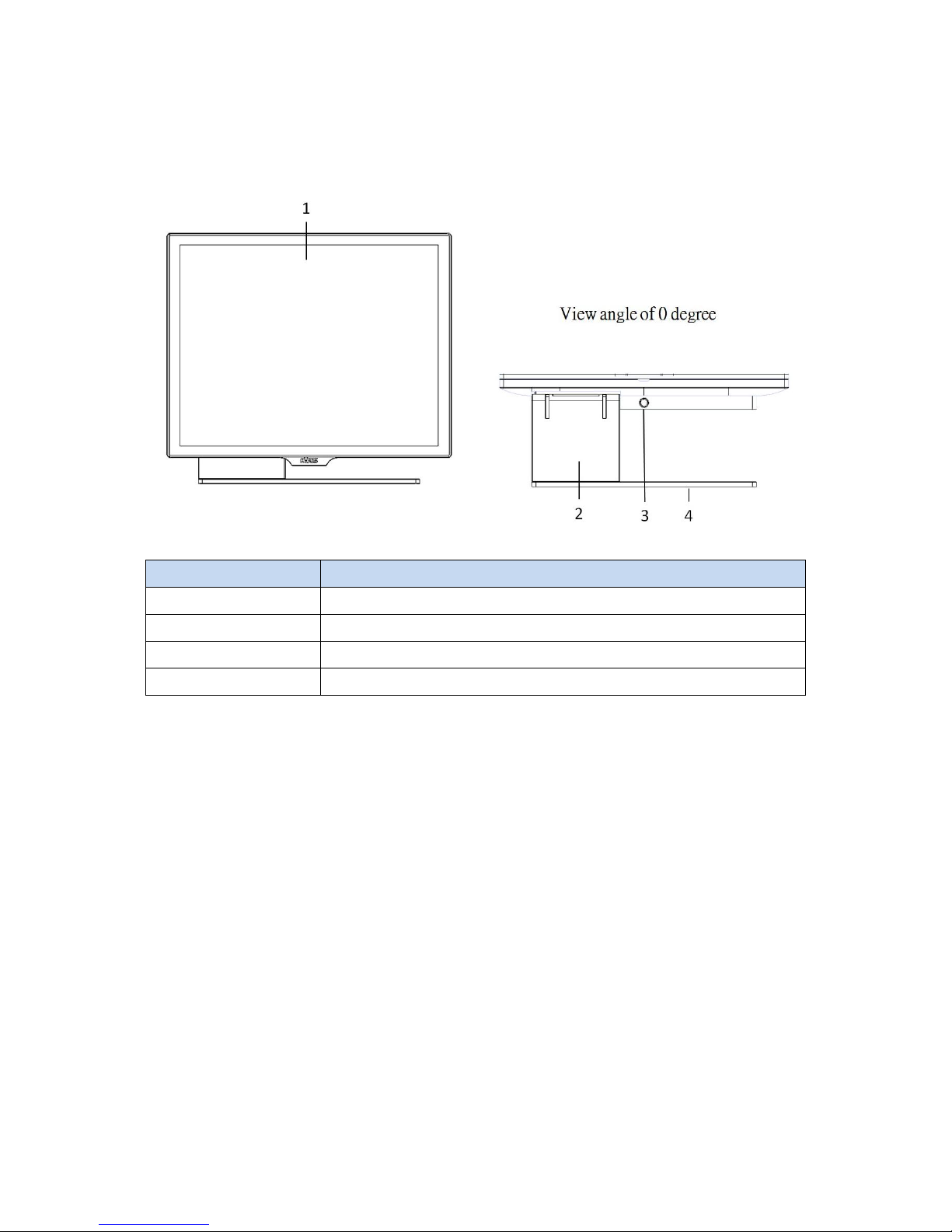
2.1 Front View
Number
Description
1
Bezel Free Panel PC
2
L-Stand
3
System Cover Release Button
4
Base Plate

5
2.2 Rear View
Number
Description
5
Attachment-type Customer Display (YUNO-VFD)
service door
6
System Cover
7
service door for peripherals
8
VESA mount (75mm x 75mm)
9
Rear Side Cable service door
10
L-Stand Cover
Rear View of YUNO-151K for reference :
6
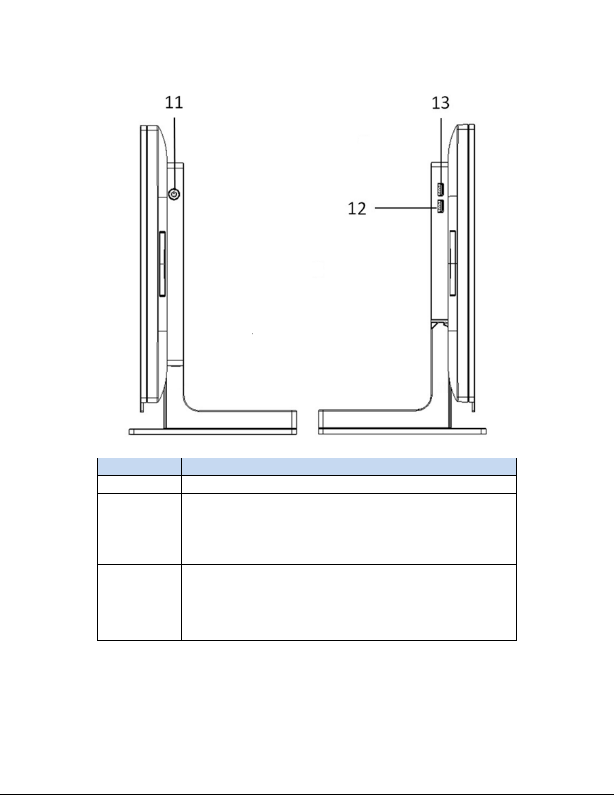
2.3 Side View
Number
Description
11
Power Button
12
X72 motherboard & Touch Screen Board : 1 x USB 2.0 (Type A)
X7D motherboard : 1 x USB 3.0 (Type A)
13
X72 and X7D motherboard : 1 x USB 3.0 (Type A)
Touch Screen Board : 1 x USB 2.0 (Type A)
7
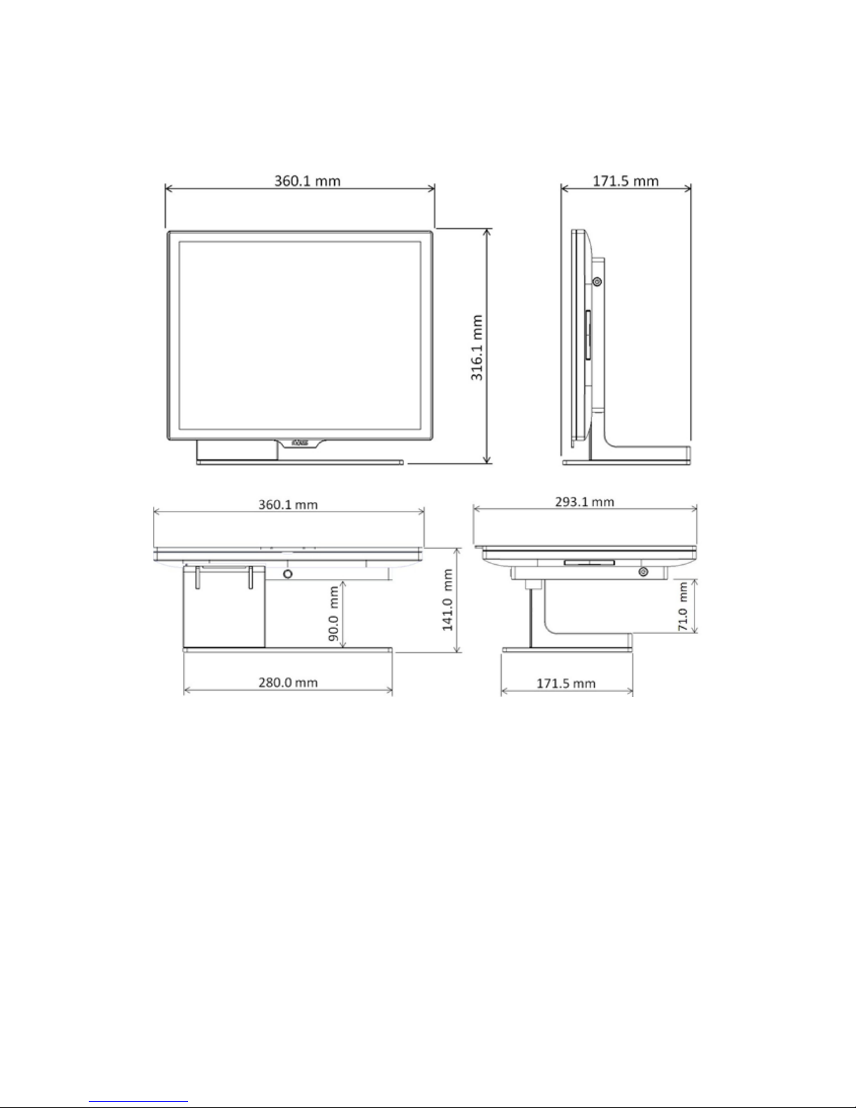
2.4 Dimension
For YUNO-151 / YUNO-151TM

8
For YUNO-156 / YUNO-156-50KH / YUNO-156TM

9
For YUNO-151K

10
2.5 I/O View
2.5.1 POS System series
YUNO-151 / 156 / 156-50KH YUNO-151K
Bottom-up View
Right-side View
Bottom-up View
Number
Description
a
DC-IN jack
b
Combo Audio jack (3.5mm 4 conductor)
c
COM1~4 (from right to left) (RJ50 Connector)
d
LAN (RJ45 Connector)
e
4 x USB 2.0 (Type A)
f
Cash Drawer (RJ12 Connector)
g
mini DP (Display Port)
h
reserved for Wi-Fi /Bluetooth
Right-side View
Number
Description
i
1 x USB 3.0 (Type A)
j
X72 motherboard : 1 x USB 2.0 (Type A)
X7D motherboard : 1 x USB 3.0 (Type A)

11
2.5.2 Touch Monitor series
j i h
g
a b c d e f
Bottom-up View
Right-side View

12
Number
Description
a
DC-IN jack
b
DVI-IN Connector
c
VGA-IN Connector
d
DP-IN Connector
e
USB 2.0 (Type B)
f
Combo Audio jack (3.5mm 4 conductor)
g
USB 2.0 (Type A)
h
DP-OUT 40-pin Connector
i
LVDS 50-pin Connector
j
OSD Control
13
3. POS System / Touch Monitor Assembly & Disassembly
Since YUNO-151K is an alternative Panel PC SKU out from standard YUNO-151, its
difference is without the L-Base part. While Touch Monitor series share the same outlook of
POS System series, diagrams of YUNO-151 is used as a representative of both YUNO POS
System series and Touch Monitor series for elaboration in the rest of this manual.
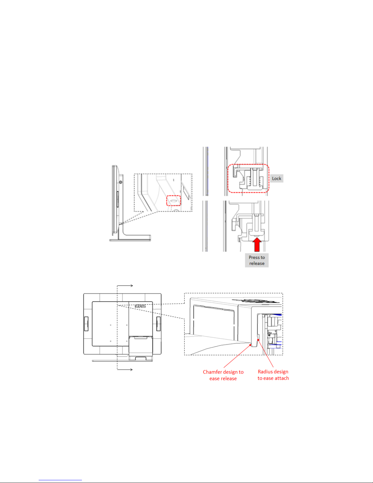
3.1 Open the System Cover
Open the System Cover by pressing the System Cover Release Button.
14
3.2 Replace the Storage Disk Drive
YUNO offers two 2.5" drive bays of height 7 mm each to allow you to equip it with a
configuration of one primary HDD or SSD on the upper bay and one secondary SSD on
the lower bay.
*Please note that if you are replacing your only HDD or SSD, you will need to reinstall
your operating system after replacing it.
Make sure the unit is powered off before starting.
Please follow the below steps to finish the replacement :
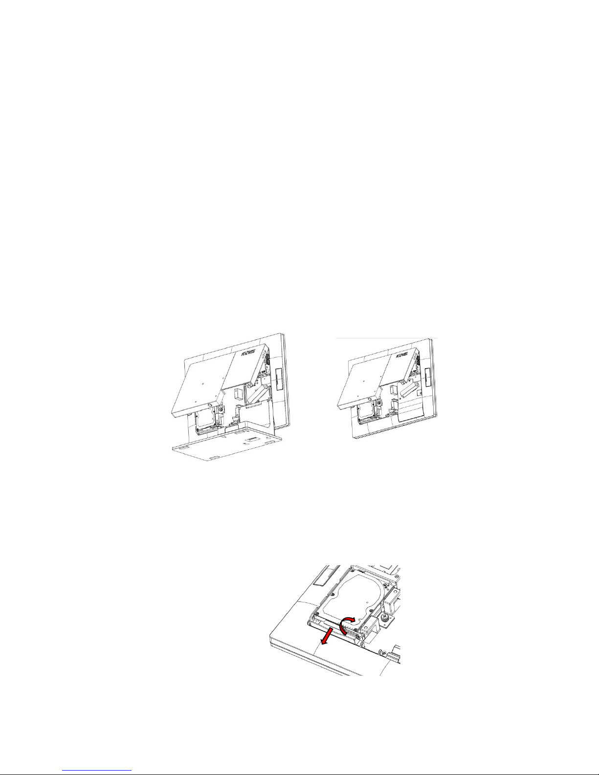
1. Remove the System Cover
To open the System Cover, please refer to the procedures described in Chapter
3-1 and remove it.
YUNO-151 / 156 / 156-50KH
YUNO-151K
2. Remove the old drive (if applicable).
If you are removing a HDD or SSD, make sure all of the cables are disconnected
from both the motherboard and the power supply. Rotate the Releasing Handler to
unlock the storage disk drive and slide it out of the housing.
1
2
15
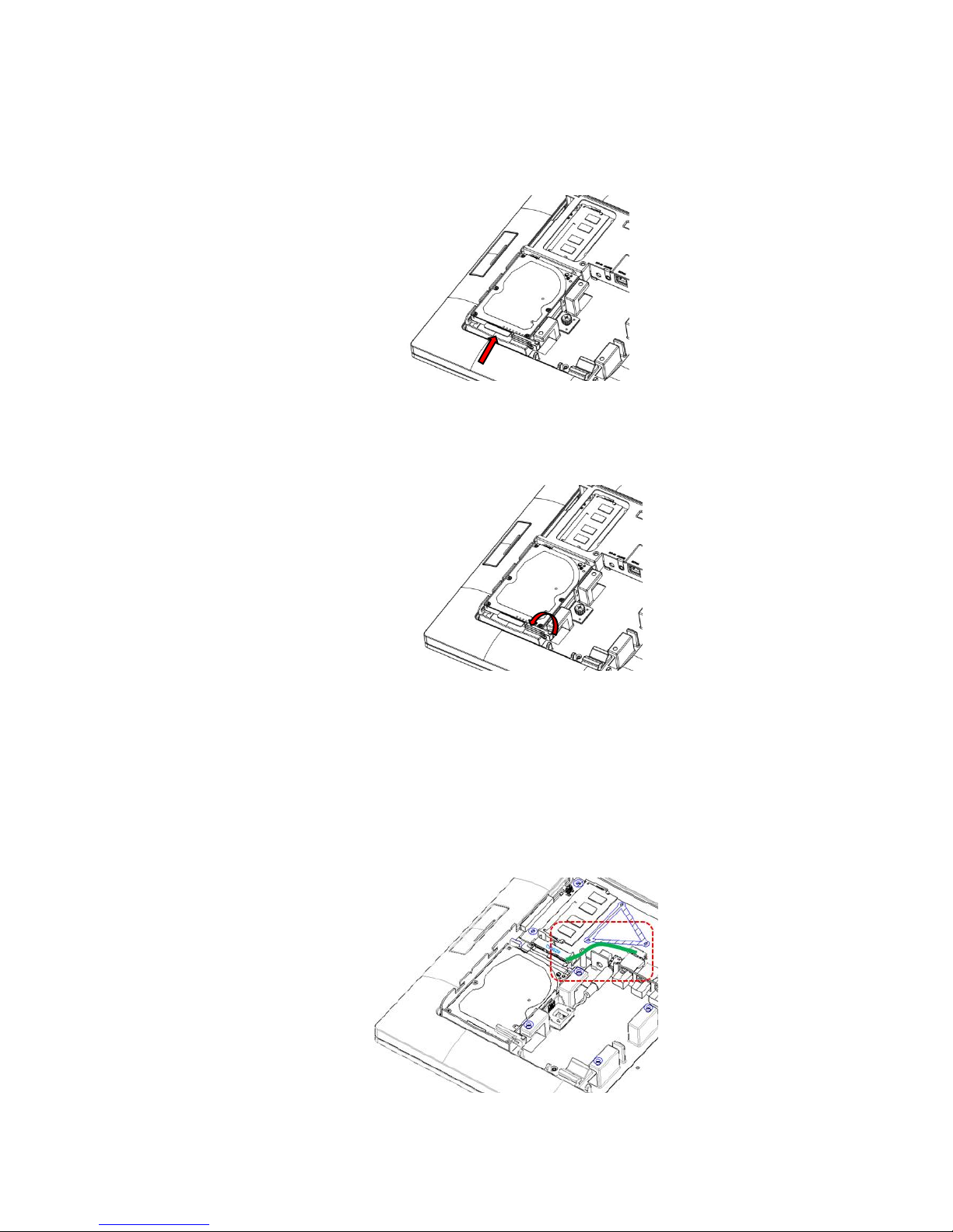
3. Insert your new drive.
Remove it from the antistatic packaging and slide it into your target drive bay of the
storage housing.
4. Secure the storage disk drive.
Once the storage disk drive has been completely inserted, rotate the Releasing
Handler to lock it properly.
5. Connect the storage disk drive to the motherboard.
*If you are connecting your primary storage disk drive, the SATA cable should be
plugged into the first SATA channel, which is labeled as SATA0. Refer to Chapter 6
about the motherboard configuration for detailed information.
Secondary drive should be connected to the next available SATA1 channel.
This manual suits for next models
9
Table of contents
Other AURES Touch Terminal manuals

AURES
AURES TMC 7000 Troubleshooting guide

AURES
AURES TWIST-MB-1900 User manual

AURES
AURES NINO II User manual

AURES
AURES TRX 3000 User manual

AURES
AURES JAZZ-BASE151 User manual

AURES
AURES TRX 3000 User manual

AURES
AURES Odysse II User manual

AURES
AURES YUNO-K170-BLACK User manual

AURES
AURES YUNO II User manual

AURES
AURES TEOS WIDE User manual


