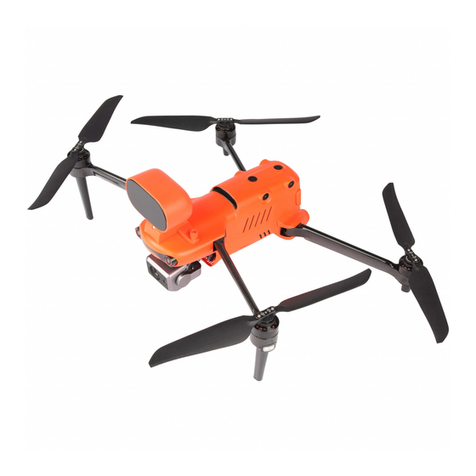
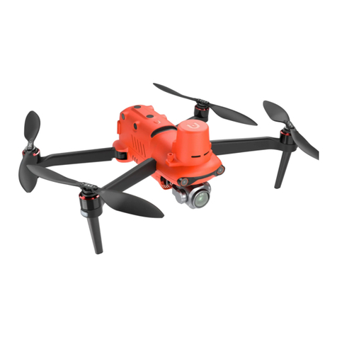
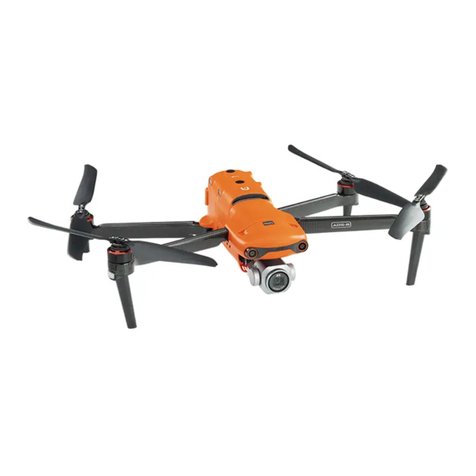
Autel EVO Max 4T User manual

User Manual
V1. 0 2023.05


Introduction
Thank you for purchasing and using the Autel Robotics EVO Max 4T aircraft (hereinafter
referred to as "EVO Max 4T").
The EVO Max 4T user manual is provided with the product, please keep this manual on
hand so that you can refer to it at any time when needed. Before using this product, please
carefully read the operation steps and precautions in this manual, so that you can quickly
understand the characteristics and usage methods of this product, so as to ensure safe use
and best practices of the product.
The following symbols are used in this manual to draw the user's attention to important
safety and operating information. Please be sure to follow the notes or requirements under
each symbol, otherwise, it may affect the safety features of the product or cause personal
injury.
Symbol Definition
Warning: Alerts to a potentially hazardous situation.
Important: Reminds the user to pay attention to a point.
References: Page numbers to help you find chapters that explain in
greater detail.
Remarks: Supplementary information.
Tips: Quick tips to get the best possible experience.
Trademark Information
, Autel Enterprise™ and trademarks are registered trademarks
of the Autel Robotics Co., Ltd. (hereinafter referred to as "Autel Robotics").
Copyright Warnings
This manual is copyrighted by Autel Robotics Co., Ltd. All copyrights, trademark rights,
patent rights, trade secrets and other intellectual property rights in this manual, as well as all
information related to this manual, are protected by the laws and regulations of the product's
origin country and relevant copyright laws within the country of sale. Autel Robotics enjoys the
above mentioned intellectual property rights. No person or organization may reproduce or
retransmit any part of this manual in any form or by any means (including but not limited to
electronic, mechanical, photocopying, recording or other means) without the express written
consent of Autel Robotics. The final interpretation right of this document and all related
documents of this product belongs to the producer of this document. This document is subject
to update without notice.

Documentation
Autel Robotics provides the following documents and tutorial videos for you to use EVO
Max 4T.
Material Description
"Packing List" A list of everything that should be included in the box.
"Disclaimer and Safety
Operation Guidelines"
Instructions on how to operate the product safely.
"Battery Safety Operation
Guidelines" Basic knowledge and safe handling of batteries.
"Quick Start Guide" Basic knowledge of operating the product.
"User Manual"
Instruct you to master the operation method of the
product proficiently.
"Maintenance Manual"
Provide professional advice and precautions in inspection,
maintenance to assist you in completing daily
maintenance operations.
Tutorial Videos
To watch EVO Max 4T tutorials, please scan the QR code or visit:
https://www.autelrobotics.com/article/135.html
Addtional Downloads
To download essential software and documents for the EVO Max 4T, please visit:
https://www.autelrobotics.com/download/591.html
Please make sure to check the aircraft and other parts listed in the product list in the
packing box. Do not use incompatible parts or try to modify the aircraft in any way that
does not comply with the official instructions.

Manual Guide
This manual contains 6 main chapters and 1 appendix, users can use the contents page or
the following guide to find the corresponding chapters according to their needs.
Chapter Chapter Overview Purpose and Core Content
Chapter 1
Aircraft
Introduce the purpose,
function and composition
of the EVO Max 4T aircraft
in detail.
After reading this chapter, the user can
have a clear understanding of the
various parts of the aircraft and the
functions of the aircraft.
Chapter 2
Remote Controller
Introduce the operation
instructions of the Autel
Remote Controller V3.
After reading this chapter, users can
quickly grasp the buttons and software
functions of the remote controller,
including app functionality. This chapter
will teach users how to use the remote
controller to its maximum potential.
Chapter 3
Smart Battery
Introduce the function,
use, storage and disposal
of EVO Max 4T smart
battery in detail.
After reading this chapter, users can
quickly grasp how to use, store and
dispose of batteries.
Chapter 4
Autel Enterprise App
Introduce the operation
instructions of the Autel
Enterprise App in detail.
After reading this chapter, users can
quickly master the functions of Autel
Enterprise App and control the aircraft
in the best way.
Chapter 5
First Flight
Introduce in detail the
precautions, preparations,
inspections and basic
operations of the first
flight.
After reading this chapter, the user can
master the basics of flying the EVO Max
4T.
Chapter 6
Firmware Update
And Maintenance
Introduce in detail the
online update methods of
the product's embedded
firmware, device
calibration, and
maintenance.
After reading this chapter, users can
quickly grasp how to update the EVO
Max 4T firmware, how to calibrate the
compass and IMU, and how to maintain
and store the product in the best way.
Appendix A
Product
Specifications
Introduce the
specifications of EVO Max
4T in detail.
After reading this chapter, users can
quickly understand the detailed
performance and functional parameters
of EVO Max 4T.
Warranty Policy
Autel Robotics guarantees users who purchase products through its official authorized
channels that under normal use, the Autel Robotics products you purchase will be free from
material and workmanship defects during the warranty period. The warranty period of this
product is calculated from the day you receive the product. If you cannot provide valid evidence
such as the purchase invoice, the warranty start date will be postponed by 90 days from the
date of manufacture indicated by Autel Robotics.
For the after-sales policy of the product, please visit:
https://www.autelrobotics.com/page/policy
After-Sales Support
Please call the official hotline at (844) MY AUTEL or (844) 692-88 35, or email to
support@autelrobotics.com for technical support.
Maintenance Service
If your equipment needs to be inspected or repaired, please contact Autel Robotics
through the following methods:
Email: after-sale@autelrobotics.com or support@autelrobotics.com.
Call Autel Robotics for Technical Support, via our toll-free number:
(844) MY AUTEL or (844) 692-88 35
Contact dealers authorized by Autel Robotics.
All data stored on the product may be erased during the repair process. To avoid data
loss, please back up important files in your aircraft or remote controller before the
product is under warranty.

Table of Contents
Chapter 1 Aircraft 1
1.1 Aircraft Introduction 1
1.1.1 Aircraft Front View 1
1.1.2 Aircraft Rear View 2
1.1.3 Aircraft Top-Down, Bottom-Up View 3
1.1.4 Description of Flight Indicators 5
1.2 Gimbal Camera 6
1.2.1 Introduction to the Gimbal Camera 6
1.2.2 Removing/Installing the Gimbal Camera 8
1.3 Flight Control System 11
1.3.1 Flight Modes 11
1.3.2 Speed Modes 12
1.3.3 Intelligent Flight Function 13
1.4 Data Transmission 13
1.4.1 Install/Remove microSD card 13
1.4.2 Connecting to PC/MAC 14
Chapter 2 Remote Controller 15
2.1 Introduction 15
2.1.1 Remote Controller Top-Down View 15
2.1.2 Remote Controller Front View 16
2.1.3 Remote Controller Rear View 17
2.2 Preparation Before Use 18
2.2.1 Installing the Remote Controller Strap (as required) 18
2.2.2 Install/Store Command Sticks 18
2.2.3 Checking Battery Level and Charge 19
2.2.4 Adjusting the Antenna Position 20
2.2.5 Pairing (Connecting to Aircraft) 20
2.2.6 Forced Frequency Pairing 21
2.2.7 Remote Controller Calibration 22
2.3 Remote Controller Main Interface 23
2.3.1 Shortcut Menu 24
2.4 Operating Instructions 25
2.4.1 Command Stick Description 25
2.4.2 Set Command Stick Modes 26
2.4.3 Custom Keys C1, C2 28
2.4.4 Automatic Takeoff/Return, Pause 28
2.4.5 Turn On/Off the Remote Controller Prompt Sound 30
2.5 Autel SkyLink Image Transmission Function 30

2.6 Output Function 31
2.6.1 HDMI Interface 31
Chapter 3 Smart Battery 32
3.1 Battery Introduction 32
3.1.1 Battery Appearance Introduction 32
3.2 Battery Operation Instructions 33
3.2.1 Installing/Removing the Battery 33
3.2.2 Turn On/Off The Battery 34
3.2.3 Check Battery Level 34
3.2.4 Charging 35
3.3 Battery Functions 36
3.3.1 Battery Self-Heating Function 36
3.3.2 Additional Features 37
3.4 Storage and Handling of Batteries 38
3.4.1 Battery Storage 38
3.4.2 Battery Self-Discharge Protection 38
3.4.3 Battery Replacement Standards 38
3.4.4 Battery Recycling 39
Chapter 4 Autel Enterprise App 40
4.1 Software Introduction 40
4.2 Home Page Guide 40
4.3 Settings Page (Overview) 42
4.3.1 Flight Control Parameter Settings 42
4.3.2 Obstacle Avoidance Settings 43
4.3.3 Remote Controller Settings 45
4.3.4 Image Transmission Settings 46
4.3.5 Battery Level of the Aircraft 47
4.3.6 Gimbal Settings 48
4.3.7 More 49
4.4 Status Notification Bar 50
4.5 Shortcut Toolbar 51
4.6 Entering the "Maps" Interface 53
4.7 Zoom Camera Interface 55
4.8 Thermal Camera Interface 56
4.9 Camera Menu 58
4.10 Attitude Ball 60
4.11 Route Missions (Toolbox) 61
4.11.1 Pre-Flight Inspection 61
4.11.2 Waypoint Missions 62
4.11.3 Resume Mission 70

4.11.4 Mission History 71
4.12 Service Center (Tools) 72
Chapter 5 First Flight 73
5.1 Instructions for First Flight 73
5.2 Flight Precautions 73
5.2.1 Flight Safety 73
5.2.2 No-Fly Zones 74
5.2.3 Waiver Application 74
5.3 Pre-Flight Preparations 74
5.3.1 Unpacking 74
5.3.2 Charging 76
5.3.3 Preparing the Aircraft 77
5.3.4 Installing/Removing Propellers 78
5.3.5 Preparing the Remote Controller 79
5.3.6 Login, Pairing, Activation (activation only upon first use) 80
5.3.7 Novice Guide (first time use only) 81
5.3.8 Reconnect the aircraft (not required by default, required after disconnection) 81
5.4 Pre-Flight Inspection 81
5.5 Basic Flight Process 82
5.5.1 Start/Stop the Aircraft 83
5.5.2 Takeoff/Landing Aircraft 84
5.5.3 Control the Aircraft (Default Mode 2) 85
Chapter 6 Firmware Update and Maintenance 86
6.1 Firmware Downloads and Update 86
6.1.1 Online Updates 86
6.2 Equipment Calibration 87
6.2.1 Compass Calibration 87
6.2.2 IMU Calibration 88
6.3 Aircraft Care and Maintenance 88
6.3.1 Power System Inspection 89
6.3.2 Aircraft Frame Inspection Items 90
6.3.3 Storage and Maintenance 91
6.4 Battery Maintenance 91
6.4.1 Battery Maintenance 91
6.4.2 Battery Maintenance Check Items 92
6.4.3 Standard Charging and Discharging Process 92
6.5 Wearable Parts List 92
6.6 Warranty Policy 93


Chapter 1 Aircraft 1
EVO Max 4T User Manual
Chapter 1 Aircraft
1.1 Aircraft Introduction
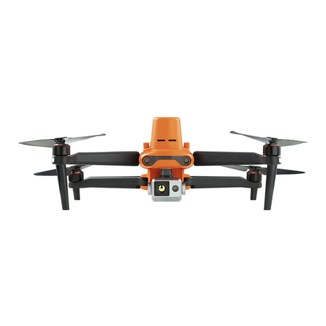
EVO Max 4T is equipped with a wide-angle camera, zoom camera, infrared thermal imaging
camera and laser rangefinder, supports visible light 8K ultra-high-definition resolution video
recording, 10x optical zoom, 640×512 high-definition thermal imaging, and (up to 1.2km) can
use its laser rangefinder. The flight platform is equipped with an industry-leading 8-core
processing chip, has powerful autonomous flight and self-organizing network mission
capabilities, is equipped with a visual perception system and a millimeter-wave radar
perception system, and has all-weather, omnidirectional obstacle avoidance system. The
included Autel Enterprise app provides users with various task modes such as 3D routes,
waypoint missions, rectangular or polygonal missions, oblique photography, etc. Users can
import captured photos into the modeling software for 2D mapping or 3D model
reconstruction. Security, inspection, surveying and mapping and other industries are
empowered through the use of this product.
1.1.1 Aircraft Front View
Figure 1-1 EVO Max 4T Front View
Table 1-1 EVO Max 4T Front View Description
No. Name Description
1 Propeller
Use the air flow to generate kinetic energy, and then convert
the kinetic energy into thrust to push the aircraft forward.
2 Motor Used to drive the propeller to rotate.

2Chapter 1 Aircraft
EVO Max 4T User Manual
3 LED Indicators
The LED indicator light located on the front arms, a steady blue
color is emitted, used to identify the front-facing direction of
the aircraft.
4 Landing Gear
Used to support the aircraft to avoid damage to the bottom of
the fuselage.
5
Forward Vision
System
Used to sense the obstacles ahead and avoid the aircraft from
colliding with them.
6 Gimbal Camera
The 4T gimbal integrates four sensor systems including
wide-angle camera, zoom camera, infrared thermal imaging
camera and laser rangefinder.
1.1.2 Aircraft Rear View
Figure 1-2 EVO Max 4T Rear View
Table 1-2 EVO Max 4T Rear View Details
No. Name Description
7 Aircraft Battery Used to provide energy for aircraft operation.
8
Rear Vision
Camera
Used to sense the obstacles in the rear and avoid the aircraft
from colliding with them.
9
Power Button
Press and hold the power button for 3 seconds to start the
aircraft.
Pairing Button Quickly press the power button twice to enter pairing mode.
10
microSD Card
Slot
For inserting a microSD card.
11
External SSD
Interface
For connecting an external SSD.
12
USB Type-C
Interface
Used to connect to a computer for firmware updates or
debugging.

Chapter 1 Aircraft 3
EVO Max 4T User Manual
13 Rear Arm LED
Indicators
Used to display the current flight status of the aircraft.
The USB Type-C port of the aircraft cannot be used for charging. Do not connect the
included remote controller charger. For charging the aircraft, please refer to "2.2.3
Checking Battery Level and Charge" in Chapter 2 Remote Controller and "3.2.4 Charging"
in Chapter 3 Smart Battery.
1.1.3 Aircraft Top-Down, Bottom-Up View
Figure 1-3 EVO Max 4T Top-Down View
Table 1-3 EVO Max 4T Top-Down View Details
No. Name Description
14 Mount Extension
Interface
More types of additional mounts can be provided to the aircraft
through the expansion interface, such as speakers, strobes, and
RTK modules.
15 Upper Night Lights
Can emit high-intensity flashing lights to indicate the position of
the aircraft at night to avoid air traffic accidents.
16
Upward Vision
System
Used to sense obstacles above, and to the left and right of the
aircraft and avoid collisions.

4Chapter 1 Aircraft
EVO Max 4T User Manual
Figure 1-4 EVO Max 4T Bottom-Up View
Table 1-4 EVO Max 4T Bottom-Up Details
No. Name Description
17
Downward Vision
System Used to sense obstacles below and avoid collisions.
18 LED Landing Light
Provide lighting for the aircraft when it lands, and assist the
downward vision obstacle avoidance sensor.
There is a protective cover under the battery on the rear side of the fuselage to protect
the microSD card slot, external SSD interface, and USB Type-C interface. Please make sure
that the protective cover is closed during the flight.
Do not disassemble the components that have been installed at the factory (except for
the components explicitly permitted in the des
cription in this manual), otherwise the
product warranty will void.
Please prevent the 4 millimeter-wave rad
ars inside the fuselage from being blocked by
foreign objects. The positions of the four millimeter-wave radars are located in the middle
of the forward vision system, the rear vision system, the top shell of the fuselage, and the
bottom shell of the fuselage.

Chapter 1 Aircraft 5
EVO Max 4T User Manual
1.1.4 Description of Flight Indicators
There is an LED indicator at the end of each arm of the aircraft. The LED indicators on the
front arms will be steady blue after lit up, which can help you identify the direction of the
aircraft's nose; the LED indicators on the rear arms will display the current flight status of the
aircraft. Table 1-6 below shows the meanings of the tail LED indicators.
Figure 1-5 Flight Lights
Table 1-5 Description of the Indicator Lights on the Arms
No. Name Description
1 Front Arm LED
Indicator
LED indicator lights at the end of the front arms on the left and
right sides, turning blue when lit, used to identify the
front-facing direction of the aircraft.
2 Rear Arm LED
Indicator
LED indicator lights at the end of the rear arms on the left and
right sides, used to display the current flight status of the
aircraft.
Table 1-6 Description of the Indicator Lights on Rear Legs
Indicator status
(R: red G: green Y: yellow)
Meaning
Normal
RYG– Alternating / Fast Flashing System Wake-Up / Self-Test
G– Slow Blinking Aircraft is in GNSS Mode / Visual Positioning
Calibration
Y– Fast Blinking Magnetometer/IMU Calibration Data Collection
G– Fast Blinking Magnetometer/IMU Calibration Goes to the Next Step
G– Always On Magnetometer/IMU Calibration Successful
R– Always On Magnetometer/IMU Calibration Failed
Warning
Y– Slow Flashing Aircraft is in ATTI Mode
Y – Fast Blinking Remote Controller Not Connected to Aircraft
R– Slow Flash Low Battery Warning

6Chapter 1 Aircraft
EVO Max 4T User Manual
R– Fast Flashing Critical Low Battery Alert
R– Always On IMU Abnormal / Illegal Battery
Slow flashing: flashing once every 2s. Fast flashing: flashes twice every 1s.
1.2 Gimbal Camera
The EVO Max 4T integrates four sensor systems: a wide-angle camera, zoom camera,
infrared thermal imaging camera and laser rangefinder.
1.2.1 Introduction to the Gimbal Camera
The EVO Max 4T gimbal camera has a high-precision three-axis motor structure, which can
keep the camera stable when the aircraft is flying, thus ensuring image stability and clarity. The
mechanical rotation angle of the three-axis motor of the gimbal (pitch: -135°~45°; roll: -45°~45°;
Yaw: -45°~45°) is shown in Figure 1-6 here.
Figure 1-6 Gimbal Camera

Chapter 1 Aircraft 7
EVO Max 4T User Manual
Table 1-7 Gimbal Camera Details
No. Name Description
1 Cylindrical Holes
The two cylindrical holes at the front of the gimbal camera are
used to fix one side of the gimbal camera to the two "fixed pins"
in the "aircraft nose gimbal cabin".
2 Yaw Axis Motor It is used to control the moving range of the camera to rotate
left or right with its own axis (mechanical range: -45°~45°).
3 Laser Range
Finder
The distance is accurately determined by measuring the time
from the start of the laser emission to the time when the laser
is reflected from the target.
4 Wide Angle
Camera
1/1.28" CMOS, 50 million effective pixels. The wide-angle
camera is used to capture images with a larger field of view
within a shorter shooting distance.
5 Dampener Mount Used to support dampeners and gimbal cameras, etc.
6 Dampener Used to buffer the vibration of the gimbal camera.
7 Roll Axis Motor Used to control the moving range of the camera to roll left or
right (mechanical range: -45°~45°).
8 Infrared Thermal
Imaging Camera
radiometric measurement range: -20℃to 150℃, 0℃to 550℃.
The infrared thermal imaging camera is used for radiometric
measurement and night vision, which can monitor the
temperature distribution of the measured target in real time, so
as to judge the state of the target.
9 Pitch Axis Motor
It is used to control the moving range of the camera up or down
(mechanical range: -135° to 45°, controllable movement range:
-90° to 30°).
10 Zoom Camera 1/2" CMOS, 48 million effective pixels. The zoom camera is used
to shoot distant scenes, making the distant scenes clearer.
11 Connector Cover
The protective cover above the connector is used to fix the
other side of the gimbal camera to the bottom of the aircraft
fuselage.
12 Connector
The connector of the gimbal camera is connected to the
connector slot at the bottom of the aircraft fuselage.
In order to ensure that the product can work normally, the ambient temperature during
use must be between -20°C and 50°C.
Be sure to use the gimbal protective cover to fix the gimbal camera, especia
lly when
transferring or storing the aircraft, to avoid da
mage to the gimbal camera due to
accidental rotation or bumping.
Please remove the protective cover of the gimbal before turning on the gimbal, otherwise
it may cause damage to the gimbal motor and circuit.
When turning on the power switch of the aircraft, the gimbal will automatically rotate to
perform self-check and calibration, please make sure there is no object near the gimbal to

8Chapter 1 Aircraft
EVO Max 4T User Manual
hinder its movement.
1.2.2 Removing/Installing the Gimbal Camera
Removing the Gimbal Camera
The aircraft adopts a detachable gimbal design, please refer to the following disassembly
steps:
1) Place the aircraft on a level surface with the bottom of the fuselage facing up.
2) Use a Phillips 2.0 screwdriver to unscrew the two screws fixing the "connector
protection cover", as shown in Figure 1-7.
3) Slightly lift the "connector protection cover" and slide it back and up to take out the
gimbal camera, as shown in Figure 1-8 below.
Figure 1-7 Remove the two screws securing the Connector Cover
When turning the aircraft upside down to remove the gimbal camera, please protect the
upward vision system of the aircraft to avoid scratches.

Chapter 1 Aircraft 9
EVO Max 4T User Manual
Figure 1-8 Slide back and up to take out the gimbal camera
Installing the Gimbal Camera
1) After aligning the cylindrical hole on the front end of the gimbal camera with the two
fixed pins in the aircraft nose gimbal cabin, push and slide the gimbal camera forward
until the connector protection cover is aligned Connector slot, as shown in Figure 1-9.
Please make sure that the Connector Cover of the gimbal camera is aligned with the
Connector Slot at the bottom of the fuselage, otherwise it will affect the connection
between the gimbal camera and the aircraft.

10 Chapter 1 Aircraft
EVO Max 4T User Manual
Figure 1-9 Slide down and forward to install the gimbal camera
2) Gently push down the "connector protection cover" to the bottom, so that the
connector under the "connector protection cover" is inserted into the "connector slot",
and the "connector protection cover" needs to be flush with the bottom of the aircraft.
3) Insert two screws into the two holes of the "connector protection cover", and tighten
them with a Phillips 2.0 screwdriver, as shown in Figure 1-10.
4) Press and hold the battery power button for 3 seconds to power on the aircraft. If the
connector cable of the gimbal camera is connected correctly, the gimbal will
automatically rotate the camera to perform a self-test.
After installing the gimbal camera to the aircraft, please ensure that all parts are fully
fixed to avoid loss due to functional failures caused by loose assembly of the gimbal
camera during flight.
Other manuals for EVO Max 4T
1
Table of contents
Other Autel Drone manuals

Autel
Autel EVO Lite Series User manual

Autel
Autel EVO II Enterprise User manual

Autel
Autel EVO II Pro V3 User manual

Autel
Autel DRAGONFISH Series User manual

Autel
Autel EVO Max 4T User manual

Autel
Autel V3 Series User manual

Autel
Autel EVO II Enterprise V3 User manual

Autel
Autel V3 Series User manual

Autel
Autel EVO II Enterprise V3 User manual

Autel
Autel EVO Nano Series User manual