AUTHOR Alarm Kvant 120 User manual

OPERATING MANUAL

version 803.1
ATTENTION!
This operating manual contains the
secret authorization code intended for an emergency
unlocking of the engine. Save this manual after
installing the system.
ATTENTION!
Do not leave this operating manual with
the secret code in the car! Otherwise, the protective
functions of the system will be disabled.
Dear car owner!
Please note that the AUTHOR Alarm’s anti-theft devices
are not intended for self-installation.
We strongly recommend to install and congure the
purchased equipment only in certied installation
centers.

3
General information ............................................................ 4
Advantages of the system ................................................... 4
OPERATION CONCEPT
..................................................... 5
Engine locking ...................................................................... 5
Algorithm of deactivation ................................................. 5
Authorization (PIN-code entering) .................................. 6
Emergency authorization .................................................. 6
Service mode ........................................................................ 7
SYSTEM SETTINGS ..................................................... 9
PIN-code setting ............................................................... 9
Change of PIN-code ........................................................... 12
Motion sensor sensitivity adjustment ........................... 13
Reset to factory settings .................................................. 15
KVANT Immobilizer options ............................................. 16
WIRING MAP ............................................................... 18
REFERENCE INFORMATION ........................................ 26
TABLE OF CONTENTS

4
General information
Immobilizer KVANT 120 is aimed to provide active
protection of the car by means of blocking (breaking)
electrical chains critical for the engine work. Its special
feature is the technology of blocking the engine with
the built-in normally closed circuit relay. Blocking
is disabled by entering the PIN-code using the car
standard buttons or additionally installed hidden
buttons.
KVANT does not show its presence in the car till engine
locking actuation. Moreover, due to its compact size
the device can be installed almost anywhere in a car.
KVANT is a new smart way to protect your car!
Advantages of the system
• The small size of the device allows its hidden
installation in the passenger compartment or under
hood space of the car.
• The device does not show itself till engine locking
actuation.
• The standard buttons in the passenger compartment
and resistive touch buttons on the steering wheel
are used to enter PIN-code; additional installation of
hidden buttons is possible.
• Engine blocking is possible if the following events
occur: Car starts moving, ignition started, automatic
gearbox position is changed.
• Service mode.

5
OPERATION CONCEPT
Engine locking
KVANT immobilizer prevents hijacking the car by
cutting off the engine or by disabling the engine start.
Engine locking occurs in the following cases:
• the accelerometer xed the car motion with the
ignition «on».
• the signal «Ignition» has arrived (optionally)
• the signal «Automatic gearbox change» has arrived
(this option is selected by default)
Algorithm of deactivation
Before driving the PIN-code should be entered by
pressing the standard buttons in the passenger
compartment of the car.
If the PIN-code has been entered correctly the system
gives 2 acknowledgement signals after that you can
start driving (the engine will not be locked). If the
PIN-code has not been entered or has been entered
incorrectly, KVANT locks the engine when you
start driving or there is signal from “Ignition is on”/
“Automatic gearbox change” (see p. 16).
The activation of the system security mode is effected
in 10 seconds after the ignition is off (or 2 minutes after
the PIN-code was entered, and the ignition was not
switched on). 3 short indication signals conrm that
the security mode is activated.

6
Authorization (PIN-code entering)
ATTENTION!
The initial PIN-code is set by the
specialists of the service centre. For security purposes
before driving change the initial PIN-code for the new
one and memorize it (see page 12).
Enter the PIN-code using the buttons and sequence of
pressing that was saved in the system. You can enter
PIN-code before or after ignition starting (both ways
are allowed).
It is recommended to enter PIN-code just before you
start driving. The interval between the pressing of
the buttons shall not exceed 2 seconds. There is no
difference between long and short button pressing.
When PIN-code is correct the system will signal
twice by LED or alarm buzzer conrming successful
authorization after which you can start driving.
If PIN-code is entered incorrectly conrmation signals
will not fallow and the engine will be locked when you
start driving. The second attempt to enter PIN-code is
allowed only after 5 seconds from the failed attempt
of authorisation or after turning off the ignition for 3
seconds and starting the ignition again if PIN-code was
entered after the ignition was «on».
Emergency authorization
In case you have forgot saved PIN-code you may
apply the emergency authorization procedure to start
driving.

7
The emergency authorization code is indicated on the
rst page of this operating manual and consists of 3
digits.
To apply the emergency code switch the ignition On
and immediately Off as many times as indicated by the
appropriate digit of the code. The ignition switch on/
off time and the pause between the second switch on/
off operation should not exceed 5 seconds. Before you
enter the next digit you should pause at least 5 seconds
(but not more than 15 seconds) while the ignition is off.
The successful unlocking will be conrmed by the
signals of LED or buzzer with the 3 seconds interval and
the system will switch into the mode of the new PIN-
code record for 2 minutes. We recommend you to write
down the new PIN-code immediately (see p. 12), then
to turn the ignition Off (not less than for 10 seconds)
and turn it On again. After that you can authorize in
the system with new PIN-code. If there is no possibility
to write down the new PIN-code, you can start the car
driving immediately after the emergency unlocking.
Service mode
The service mode is used for temporary deactivation
of the anti-theft device when you give your car for the
maintenance (without giving away the PIN-code and
saying about the device).
The service mode activation is carried out with the
ignition switched on or off (if the car identies the
button been pressed when ignition is off).

8
After the authorization (the current PIN-code was
entered) press 10 times any button wired to the
immobilizer entry. Press button not later than 2 minutes
after entering the PIN-code. The interval between the
pressing of the buttons shall not exceed 2 seconds.
The service mode activation will be conrmed by 10
LED or buzzer signals.
The exit from the service mode is performed by entering
the PIN-code. The 2 times indication signal will conrm
that the service mode is deactivated.
ATTENTION! Service mode is not disabled when the
power is cut off and the ignition is switched on/off.
Use the emergency authorization code to turn off the
service mode in case of emergency (p. 6).
After the deactivation of the service mode when you
try to switch the ignition on or start the engine you will
have to enter the PIN-code.
Authorization by the PIN-code after the deactivation
of the service mode is not required if the ignition was
switched on then switched off for less than 10 seconds,
and after that switched on again (the module is in
operating mode).

9
SYSTEM SETTINGS
PIN-code setting
ATTENTION!
PIN-code setting is allowed only for
a new «out of box» device or for a device with the
restored factory settings (p. 15).
The procedure of PIN-code setting when KVANT is
connected under the minimum connections scheme (p.
18) to two standard analogue buttons (p. 20) or to the
«inow-free» resistor array (p. 22):
1. Switch power off from device (red wire).
2. Connect the grey wire to the red wire.
3. Apply power +12V on the red wire. System will pass
into the learning mode, the dual indication signals
of the LED or the buzzer will be provided each 3
seconds.
4. Disconnect the grey wire, without removing the
power from the red wire. The indication will shift to
triple signal, once in 3 seconds.
5. Enter the PIN-code using the buttons connected
to the device inputs. Every click shall be followed
by indication signal of LED or buzzer. The quantity
of clicks should be in the range from 2 to 9. The
interval between keystrokes shall not exceed 2
seconds. There is no difference between long and
short keystrokes. Buttons must be pressed rmly.
The grey wire can be used as an extra button with
the «+»potential. To do this, connect it to the power
supply circuit, apply power («press the button») and
turn off the power («release the button»).

10
A different combination of buttons and sequence of
keystrokes is allowed, e.g. if you press the button
#1 twice and press the button #2 once, the system
will save all the clicks in this order. When you have
nished entering the PIN-code, the system will
provide 3 conrmation signals of LED or buzzer,
regardless the number of clicks.
6. Enter the current PIN-code once again. If the codes
are matched the indication signal will be given twice.
The PIN-code will be recorded. The indication will
shift to quadruple signal, once in 3 seconds. To exit
from the PIN-code setting mode press any button
once. If the indication signal appears only 4 times,
it means that the entered codes do not match. The
PIN-code will not be recorded. Repeat the steps 5, 6
to set the PIN-code.
7. Disconnect the red wire from power supply circuit
«+» in order to reboot the device.
8. Connect the red wire to the power supply circuit. If
necessary, connect the grey wire in order to use it as
an analogue button.
ATTENTION!
After you have entered the PIN-code, you
will not be able to enter the PIN-code setting mode
using the grey wire (until all settings are reseted to the
factory settings, page 15)
.
The procedure of PIN-code setting when KVANT is
connected to the «inow» resistor array (page 24):
1. Switch off power supply from the device (red wire)
and disconnect car battery supply.
2. Connect the grey wire to the red wire.
3. Apply power +12V on the red and grey wires.

11
System will switch into the learning mode, the dual
indication signals of the LED or the buzzer will be
provided once in 3 seconds.
4. Disconnect the grey wire, without removing the
power from the red wire. The indication will shift to
triple signal once in 3 seconds.
5. Enter the PIN-code by pressing the buttons of the
resistor array. Every click shall be followed by an
indication signal of LED or buzzer. The number of
keystrokes shall be in the range from 2 to 9. The
interval between the keystrokes shall not exceed 2
seconds. There is no difference between long and
short keystrokes. Buttons must be pressed rmly.
The grey wire can be used as an extra button with
the «+»potential. To do this, connect it to the power
supply circuit, apply power («press the button») and
turn off the power («release the button»).
A different combination of buttons and sequence of
keystrokes is allowed, e.g. if you press the button
#1 twice and press the button #2 once, the system
will save all the clicks in this order. When you have
nished entering the PIN-code, the system will
display 3 conrmation signals of LED or buzzer,
regardless the number of clicks.
6. Enter the current PIN-code once again. If the codes
are matched the indication signal will be given
twice. The indication will shift to quadruple signal,
once in 3 seconds.
7. Turn the ACC power on. The 5-fold indication signals
of the LED or buzzer will follow, once in 3 seconds.
8. Repeat the PIN-code setting according to the
paragraphs 5, 6. The PIN-code will be recorded.

12
If there are 4 indication signals, it means that the
PIN-codes do not match and PIN-code has not
been saved. Repeat the steps 1-8 to set PIN-code.
9. Disconnect the red wire from DC+ in order to reboot
the device.
10. Connect the red wire to the power-supply circuit.
If necessary, connect the grey wire in order to use it
as an analogue button.
Having this procedure completed, you will be able to
use the buttons on the steering wheel to enter the PIN-
code, even if there is no vehicle battery voltage.
Change of PIN-code
To ensure the condentiality the PIN-code set in
the service centre shall be changed when the car-
owner gets his/her car back from the service centre
with KVANT anti-theft system installed. Also it is
recommended to change a PIN-code if you suspect
someone has watched you entering the PIN-code.
1. Turn the ignition on without starting the engine
(only if the car does not recognise the clicking when
the ignition is off).
2. Enter the current PIN-code to authorize. There will
be 2 indication signals.
3. Enter the current PIN-code again within 2 minutes.
The device will pass to the PIN-code change mode
and the signal indication will be given every 3
seconds.
4. Enter the new PIN-code using the buttons connected
to the device inputs. Every pressing shall be followed
by the indication signal.

13
The number of pressings shall be in the range
from 2 to 9. The interval between the pressings of
the buttons shall not exceed 2 seconds. There is
no difference between long and short pressings.
Buttons must be pressed rmly.
A different combination of buttons and sequence of
keystrokes is allowed, e.g. if you press the button
#1 twice and press the button #2 once, the system
will save all the clicks in this order. When you have
nished entering the PIN-code, the system will
display 3 conrmation signals of LED or buzzer,
regardless the number of clicks.
5. Enter the current PIN-code once again. If the PIN-
codes match than there will be 2 signals and the
PIN-code will be successfully saved.
If there are 4 indication signals, it means the PIN-
code does not match and the PIN-code is not
changed. Turn off the ignition and repeat the items
1-6.
6. Turn off the ignition (if it was switched on, see p. 1).
ATTENTION! Memorize the PIN-code or write it down
after it has been changed. Do not leave PIN-code
information as well as this guide inside the car!
Motion sensor sensitivity adjustment
The motion sensor of the immobilizer provides 5
sensitivity levels (sensitivity increases from 1 to 5, by
default level 5 is activated). To change the sensitivity
level, follow these instructions:

14
1. Switch the ignition on without starting the engine.
2. Enter the current PIN-code to authorize. There will
be 2 indication signals.
3. Enter the immobilizer Setup menu (Setup menu
is available within 2 minutes after the PIN-code
entering). For this purpose press any of the buttons
connected to the device and retain it pressed during
10 seconds. The indication LED or buzzer will give a
signal once a second.
4. Press any of the connected buttons twice to enter
the sensitivity control sub-menu (see p. 16). The
indication LED or buzzer will give the quantity of
signals, which corresponds to the value of the
current sensitivity level (from 1 to 5). After that
series of dual signals will be given.
5. Set a new sensitivity level by pressing the button the
required number of times from 1 to 5. The value «1»
corresponds to the switched off sensor, the value of
«2» – to the lowest sensitivity level (response to a
strong speedup), the value of «5» – to the highest
sensitivity level (response to a weak acceleration).
Each pressure will be the conrmed by a single
signal of LED or buzzer.
The record of a new sensitivity level will be
conrmed in 3 seconds after the end of the setting
with the corresponding quantity of signals of LED or
buzzer (from 1 to 5). If the record is not performed,
the LED or buzzer will indicate single signals with
duration of 2 seconds. Turn off the ignition and
repeat the steps 1-4.
6. Turn off the ignition.

15
Reset to factory settings
ATTENTION!
When KVANT immobilizer is connected
under the «feeding» scheme (p. 24) you have to complete
the initial PIN-code setting procedure after the reset to
factory settings (p. 9). Otherwise, when the power supply
or the ignition is switched on, the LED or buzzer will
indicate single signals with duration of 2 seconds.
To reset the KVANT to factory settings (including
current PIN-code reset) follow the steps:
1. Switch on the ignition without starting the engine.
2. Enter the current PIN-code to authorize. There will
be 2 indication signals.
3. Enter the immobilizer Setup menu. For this purpose
press any of the buttons connected to the device and
retain it pressed during 10 seconds. The indication
LED or buzzer will give a signal once a second.
4. To reset to factory settings press any of the
connected buttons 9 times (see p. 16). The indication
LED or buzzer will give out 9 signals. Press the
button 9 times to conrm the reset. The indication
LED or buzzer will conrm the reset by the signal
repeated 9 times. If the reset is not performed, the
LED or buzzer will indicate single signals with the
duration of 2 seconds. To reset the settings turn off
the ignition and repeat the steps 1-3.
5. Turn off the ignition.
The reset to factory settings also can be done by
physical connection of orange wire «Status of the
service mode» to yellow-green «AT switch». When two
wires are connected power should be supplied to the
red wire.

16
KVANT Immobilizer options
The options set in default («on» or «off») are marked
with grey colour in the table. The option number
corresponds to the number of keystrokes to set the
required state of the option.
No. Option off on
1
Entering Setup menu
–
2
Motion sensor sensitivity*
1 5
3
Ignition locking
1 2
4
AT switch locking
1 2
9
Resetting
–
* setting range from 1 to 5, see p. 13 for further details
To change the option status do the following:
1. Switch on the ignition without starting the engine.
2. Enter the current PIN-code to authorize. There will
be 2 indication signals.
3. Enter the immobilizer Setup menu. For this purpose
press any of the buttons connected to the device and
retain it pressed during 10 seconds. The indication
LED or buzzer will give a signal once a second.
4. To select the option press any of the connected
buttons the number of times equal to the number
of the option in the table. The indication LED or the
buzzer will display the signals, quantity of which
corresponds to the current option value, then it will
start to display signals series, which correspond to
the option number.
5. Set the new option value by pressing any of the
connected buttons as many times as corresponds

17
to the state «switched on» or «switched off» (see
the digits corresponding the appropriate option in
the table). For example, 5 times to set the sensitivity
level «5» motion sensor or 2 times to lock on ignition.
The indication signals which correspond to the
new value will conrm its record into the system
memory. The option state will be changed.
If option value is not changed the LED or buzzer will
give single signals with duration of 2 seconds. To
change the option turn off the ignition and repeat
the steps 1-4.
6. Turn off the ignition.

18
KVANT minimum connection diagram
1. Red. +12V power supply.
2. Grey. For the system learning* Analogue regular
button «+».
3. Yellow. Ignition «+».
4. Blue. Light-emitting diode LED/ buzzer «-».
5. Black. Ground/earth.
1
+12V
+12V
2
354
ATTENTION! KVANT minimum connection scheme
feature is the limitation of the quantity of buttons for
PIN- code setting (only 1 button) and the impossibility
to block the engine by “Automatic gear box change”
signal. To avoid the indicated limitation use other
connection diagrams (p. 22-27).
Button 1
Ignition «+» LED/buzzer «-»
19
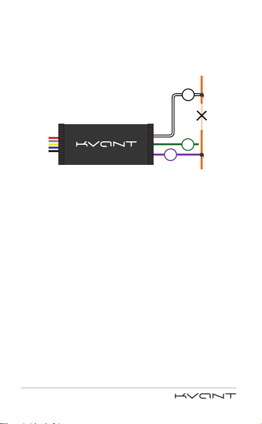
6. Purple (0,2 mm2). Normally Closed contact.
7. Green (0,2 mm2). Normally Opened contact.
8. White-black. Common wire (for circuit blocking).
* Connect the grey wire (2) to «+» in order to turn on the system learning mode
(see p. 9). Disconnect the grey wire from «+» before PIN-code setting.
6
7
8
Blocking circuit

20
KVANT wiring map
to regular analogue buttons
1. Red. +12V power supply.
2. Grey. For the system learning.* Analogue regular
button 1 «+».
3. Pink. To the white wire (5).
4. White. Analogue regular button 2 «-».
5. Brown. Ground/earth.
6. Yellow-green. AT switch «-».
7. Yel l ow. Ignition «+».
8. Orange. Status of the service mode «-».
9. Blue. Light-emitting diode LED/buzzer «-».
10. Black. Ground/earth.
3
6
10
1
9
7
8
+12V
+12V
+12V
2
5
4
Ignition «+» LED/buzzer «-»
AT switch «-»
Button 1
Button 2
Table of contents
Other AUTHOR Alarm Car Alarm manuals

AUTHOR Alarm
AUTHOR Alarm COMPASS User manual

AUTHOR Alarm
AUTHOR Alarm Kord User manual

AUTHOR Alarm
AUTHOR Alarm IGLA User manual

AUTHOR Alarm
AUTHOR Alarm RAPTOR 151 User manual

AUTHOR Alarm
AUTHOR Alarm Kvant 231 User manual

AUTHOR Alarm
AUTHOR Alarm VOLK User manual

AUTHOR Alarm
AUTHOR Alarm IGLA User manual

AUTHOR Alarm
AUTHOR Alarm TOR User manual


