AUTHOR Alarm IGLA User manual

SERVICE MANUAL


27/ 07/ 20
nRF52
Dear client!
The anti-theft systems manufactured by AUTHOR are
meant to be installed only in the certied installation
centers in your region.
The systems installed by non-certied centers or by
individuals are not subjected to warrantee and service
maintenance.

TABLE OF CONTENTS
DEVICE CONNECTION ..................................................2
Wiring diagram............................................................................. 2
Siren connection ......................................................................... 4
Additional protective contour................................................ 5
Additional contour connection.............................................. 5
FIRMWARE UPDATE......................................................6
BLED 112 drivers installation ................................................ 6
The Author Flasher software installation......................... 9
The IGLA ALARM rmware update ....................................10
Setting of the IGLA ALARM parameters ..........................13
Key fobs adding .........................................................................15
DEVICE ALIGNMENT...................................................18
Alignment with the AUTOSTART-module........................18
Alignment with ATLAS or COMPASS GSM/GPS.............19
Alignment with TOR ................................................................21
Alignment with the CONTOUR-module ...........................22
Alignment with the KORD-module ....................................23
Alignment with the KEYLESS BLOCK ...............................24
FIRST SETTINGS ADJUSTMENT AND CHOOSING
OF THE OPTIONS.........................................................27
Initial setting of the PIN-code .............................................27
The IGLA ALARM anti-theft system options ..................28
Engine blocking method........................................................30
Additional functions ................................................................31
Deleting of the key fobs.........................................................33
Key fobs adding .........................................................................33
Authentication by the key fobs of the KEYLESS BLOCK.....38
Key fobs indication table .......................................................39
Authorization (authentication) modes............................. 40
Anti-hijack mode .......................................................................41
Super AntiHiJack mode...........................................................42
Alternative service/valet button.........................................42
2
DEVICE CONNECTION
Wiring diagram
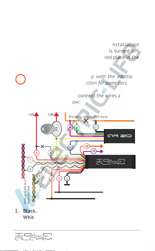
The IGLA ALARM anti-theft system installation
should be conducted when the ignition is turned off.
Thesystem should be installed in a secured place inthe
car inaccessible for criminals.
The device should be set up with the additional
module CONTOUR connection for some cars.
In order to set up the device, connect the wires according
to the wiring diagram below:
1. Black. «Ground» (permanent «minus»)
2. White-Red. LIN-bus number one.
3. Orange-Black. LIN-bus number two.
!
Vehicle LIN-bus number two
Vehicle LIN-bus number one
«Minus» siren output
End switch
Analogue relay
Ignition
lock
Vehicle CAN-bus number two
Vehicle CAN-bus
number one
3
4. White. CAN-bus number one LOW.
5. Brown. CAN-bus number one HIGH.
6. Green. CAN-bus number two LOW.
7. Pink. CAN-bus number two HIGH.
8. Red. Permanent «plus».
9.
Gray. Programing wire (for the rst adjustment
should be connected to a «plus»).1
10. Yellow. Ignition.2
11.
Blue. «Minus»-output to the analog relay (max250mA).
12.
Orange. «Minus» siren output (max 250 mA, see page
number 4).
13.
Violet. End switch (optional). In the IGLA ALARM
device the violet wire is used for connection to an
analog end switch (for example the end switch of
the hood). Connection of this wire with «Ground»
for longer than two seconds period is considered
disturbance. The characteristics of this signal have
the same nature as the characteristics of the doors,
hood and hatch disturbance.
A. Violet. Normally closed contact.
B. Green. Normally open contact.
C. Black. Common wire (COM).
Connection to the LIN-1 and LIN-2 buses may provide
the opportunity to use the LIN-buses3for the engine
start prohibition function realization. In this case
the additional relay connection is not required.
1 The gray wire (9) should be connected to a permanent «plus» for
initial recording of the PIN-code.
2 The yellow wire should be used only when connecting the analog
relay.
3 Check out the connection opportunity to the LIN-bus for
the particular make of car on the official service website
https://service.author-alarm.com/.
might be required
for some cars
4
The engine stop function may be realized by use of the
analog relay (see page number 5). The analog relay
should also be used in the case the connection to the
LIN-bus is not available in the particular car.
After the IGLA ALARM system has been connected turn
on the ignition. The car will be recognized automatically,
the indication signals will begin to blink once in three
seconds.
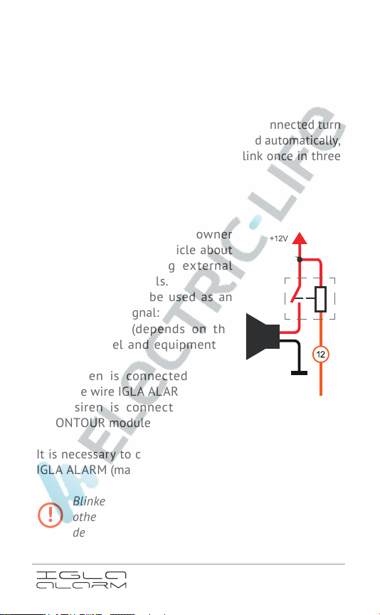
Siren connection
IGLA ALARM informs the owner
and people near the vehicle about
alarming events using external
sound and light signals.
The following can be used as an
external sound signal:
•
regular horn (depends on the
make, model and equipment of
the car)
•
the siren is connected to the
orange wire IGLA ALARM
•
the siren is connected to the
CONTOUR module
It is necessary to connect the siren to the orange wire
IGLA ALARM (max. 250 mA) via a relay.
Blinkers are normally used as light signals (some
other variants of external signals can be used
depending on the particular make of the car).
«Minus» siren output
!
5
Additional protective contour
There may be connected the additional protective
contour to the IGLA ALARM system for providing
maximal protection to the car from being theft. It
begins to work in the case the connection with the
engine operating module through the CAN-bus has been
interrupted or hindered. This type of blocking allows the
anti-hijack and the engine stop functions to be realized
in the cars where the digital type of blocking through
the CAN-bus is unavailable.
In the case the additional protective contour is already
being used by the CONTOUR hood lock module, the
additional analog relay connection to the IGLA ALARM
system is not required.
Additional contour connection
Additional contour blocking is realized through the
normally closed contact of the relay. This type of
blocking is used in the case of an emergency in the
cars for which the digital type of blocking through the
CAN-bus is not supported. Analog blocking may be
used in any circuits breaking of which may result to
the engine stopping (even if it may result to emerging
of some errors). The blocking is implemented by the
«minus»- potential appearing at the blue wire when
the ignition or the engine is ON (the status is being
monitored through the yellow «ignition» wire).
6
FIRMWARE UPDATE
The IGLA ALARM system firmware update is
implemented remotely through the Bluetooth channel
with no need to dismount the device.
In order to update the rmware, you will need to:
1.
Download and install the BLE112-module driver (the
USB-dongle should be connected to the computer).
2.
Download the archive with the Author Flasher
software and unpack it to any folder on the
computer.
3.
Transfer the IGLA ALARM to the rmware change
mode and perform the updating procedure using the
Author Flasher tool.
BLED 112 drivers installation
1.
Unpack the «Driver BLE adapter.7z»-archive content
to any folder on the computer.
2. Connect the USB-dongle to the computer.
3. Open the device manager on the computer (works
only Windows-operated computers):
Start – Control panel – Device manager
or click the right button of the mouse on the icon
This computer – Operation – Device manager.
4. Find the new device in the list of the new devices.
It may be ticked with the exclamation sign «!» as
unidentied device and may be placed into:
• Ports (COM and LPT)
• USB-controllers
• Other devices
7
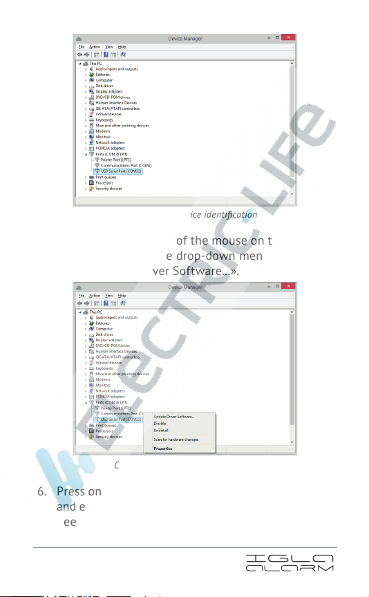
Example of the device identi cation
5. Click the right button of the mouse on the name of
the device and in the drop-down menu choose the
point «Update Driver Software...».
Choose «Update Driver Software...»
6.
Press on «Browse my computer for driver software»
and enter the path to the folder that the drivers have
been unpacked to.
8
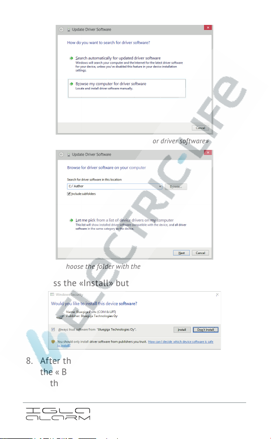
Choose «Browse my computer for driver software»
Choose the folder with the just unpacked archive
7. Press the «Install» button.
8. After the installation process has been completed,
the « Bluegiga Bluetooth Energy » device will appear
in the list of the devices.

9
9. Installation of the driver has been nished.
The Author Flasher software installation
The Author Flasher application does not require
installation and ready to be launched right after the
archive with the newest version of the application has
been unpacked.
The application is supported only by Windows‑
operated computers (Windows 7 or above).
!

10
For correct work of the application «NET framework 4.5»
may be required that can be downloaded and installed
by double click of the left button of the mouse on the
le «dotNetFx45_Full_setup.exe».
The IGLA ALARM rmware update
Situate the computer with the BLED 112 USB‑dongle
as close to the device as possible in order to arrange
a stable connection.
Transfer the device to the rmware change mode:
If the device has not been connected to the car yet or the
set rmware is for another car model follow the next steps:
1.
Twist the red and the gray wires together and
connect them to the «plus» of the power supplying
source.
2.
Connect the black wire of the device to the «ground».
Connection of the device to the CAN‑bus at this
stage is not mandatory.
If the device has already been installed in the car:
1. Turn on the ignition without starting the engine.
2.
Enter the current PIN-code or sign in with a key fob.
3. Press the accelerator1and holding it pressed, enter
the previously entered PIN-code once again.
4.
Release the accelerator when the indication signs
start appearing once in three seconds2.
The rmware update and the PIN-code change is
possible in this mode.
1 The algorithm of the initial PIN-code setting is provided on page
number 27.
2 A different operative organ is used in some of the cars instead of the
accelerator (see the ofcial website https://service.author-alarm.com/).
!
!
!

11
Perform the IGLA ALARM rmware change procedure:
1.
Open the Author Flasher application by double
click of the right button of the mouse on the
AuthorFlasher.exe le. The USB dongle should be
plugged in; otherwise the application will require
to plug it in after having been started.
2.
Choose «Select» and specify the path to the
folder where the rmware (.bin) is stored (The le
extension may be manually changed into «.hex» for
better compatibility with the older versions).

12
3.
Press «Refresh» in order to establish the connection
between the IGLA ALARM and the BLED 112
Bluetooth USB-dongle. After identication of all of
the available devices, they will appear in the device
list.
4.
Choose the device the rmware of which is planned
to be updated and press «Flash». The rmware
change/update process will be started (it normally
takes about two minutes).
5. When the process is nished, press «OK».
13
6. Turn off the ignition and turn it on again.
The PIN-code and the serial number of the device
will remain unchanged.
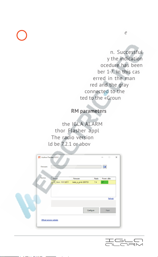
7.
Enter the valid PIN-code to sign in. Successful
rmware update will be conrmed by the indication
signs. If the rmware change procedure has been
unsuccessful, repeat steps number 1-7. In this case
the device should be transferred in the manual
rmware change mode: the red and the gray wires
are twisted together and connected to the «plus»,
the black wire is connected to the «Ground».
Setting of the IGLA ALARM parameters
The parameters of the IGLA ALARM can be adjusted
through the Author Flasher application when the
ignition is on. The radio version of the device being
adjusted should be 7.2.1 or above.
!

14
1.
Choose the IGLA ALARM among the available
devices in the list and press the «Congure»-button.
2.
Proceed to the «Read-write settings» - window and set
the new values of the parameters of the device.

15
The detailed information about the options of the
device is described in the user guide on the ofcial
website of the company
3.
Press the «Apply changes» - button when the
procedure is nished.
Key fobs adding
New key fobs can be added to the device through the
Author Flasher application when the ignition is on. The radio
version of the device should be 7.1 or above.
1.
Choose the IGLA ALARM among the available
devices in the list and press the «Congure» - button.
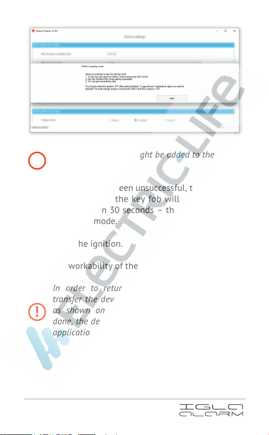
2. Transfer the device to the key fobs adding mode by
clicking on the appropriate caption in the lower part
of the window.
!

16
3. Press «OK» in the opened window.
All the key fobs and the smartphones previously
added to the device will be erased from the memory
of the device.
4.
Insert the power supplying element holding the
button on the key fob’s body pressed. The diode
should start ashing with green. After the successful
adding the diode should ash with red.
!
17
Both of the key fobs might be added to the system
at a time.
If the addition has been unsuccessful, the diode will
stop ashing and the key fob will proceed to the
«sleep»-mode in 30 seconds – the reduced energy
consumption mode.
5. Turn off the ignition.
Check the workability of the newly-added key fob.
In order to return to the device conguration,
transfer the device to the PIN-code change mode
as shown on page number 10. After having it
done, the device will appear in the Author Flasher
application among the available devices.
!
!
Other manuals for IGLA
2
Table of contents
Other AUTHOR Alarm Car Alarm manuals

AUTHOR Alarm
AUTHOR Alarm IGLA User manual

AUTHOR Alarm
AUTHOR Alarm VOLK User manual

AUTHOR Alarm
AUTHOR Alarm RAPTOR 151 User manual

AUTHOR Alarm
AUTHOR Alarm Kord User manual

AUTHOR Alarm
AUTHOR Alarm TOR User manual

AUTHOR Alarm
AUTHOR Alarm Kvant 120 User manual

AUTHOR Alarm
AUTHOR Alarm Kvant 231 User manual

AUTHOR Alarm
AUTHOR Alarm COMPASS User manual
Popular Car Alarm manuals by other brands


HID
HID ProxPass II Install guides

Audiovox
Audiovox Prestige APS-35-CL owner's manual

Mongoose
Mongoose MX40 II Series Operating & installation instructions

Audiovox
Audiovox Prestige Platinum APS-400 owner's manual

Directed Electronics
Directed Electronics 700J owner's guide

Carbine
Carbine PLUS-6800 user manual