AUTHOR Alarm RAPTOR 151 User manual

OPERATING MANUAL

version 807.1
nRF51/52
Dear car owner!
Please note that the AUTHOR Alarm’s anti-theft devices
are not intended for self-installation.
We strongly recommend to install and congure the
purchased equipment only in certied installation
centers.

3
General information ........................................................... 4
Benets of the system ........................................................ 4
OPERATION CONCEPT
...................................................... 5
Security deactivation .......................................................... 5
Authorization via key fob .................................................. 6
Authorization via PIN-code ............................................... 7
Service mode ....................................................................... 8
Engine locking ..................................................................... 9
Device number check ........................................................ 10
REFERENCE INFORMATION ........................................ 11
Options of the anti-theft system RAPTOR ................... 11
Locking method selection ................................................ 12
Firmware update ............................................................... 12
Adding or deleting key fobs ............................................. 13
TABLЕ OF CONTENTS

4
General information
RAPTOR is unique device developed to protect your car
from theft. The device has an innovative mechanism of
engine locking that uses standard wiring of the car so
there is no additional wiring that can be easily found.
The locking is deactivated with the key fob or with the
secret code.
The device can not be found by any known means.
RAPTOR does not show itself until the engine is
started. Moreover, due to its small size the device can
be installed almost anywhere in the car.
RAPTOR is a new smart way to protect your car!
Benets of the system
• Digital locking of the engine without intervention
into the car control units and circuits.
• Smart locking of the engine based on the readings
data from car sensors and car status analysis.
• The device does not show itself until the engine lock
is activated.
• For unlocking use the key fob or the secret code that
can be entered with standard car pedals.
• Service mode provides safety of the car while it is in
maintenance.

5
OPERATION CONCEPT
Security deactivation
In order to start driving you should log into the system
via one of the following ways:
• use the key fob;
• enter the Emergency code specied under the
protection layer of the plastic card.
If the key fob is detected (Emergency code is entered
correctly), the system will signal with indication, the
engine will not be locked and you can start driving. If
the key fob was not detected (Emergency code incorrect
or was not entered at all), RAPTOR will lock the engine.
In some car models the system switches to the engine
start inhibit mode after the engine is shut off. In order
to unlock the engine you should switch on the ignition
without starting the engine (without pressing the brake
pedal), enter Emergency code and start the engine.
The locking method (engine start inhibit and/or running
engine stall) depends of the RAPTOR system settings
and the car brand/model.
The security system is activated in 10 seconds after the
ignition is off.

6
Authorization via key fob
It is enough to have the key fob to authorize in the
system.
ATTENTION!
Do not leave the key fob inside the
car when the ride is over. Otherwise the anti-theft
functions of the system will be deactivated.
Get into the car, switch ON the ignition. When the key
fob is detected, the system will give out two verication
signals (see the annex), after that you can start driving.
ATTENTION!
If the battery charge in the key fob is low,
the indication will signal 6 times after the ignition is
switched ON.
If the key fob is not detected, there will be no
verication signals and if one attempts to start driving
or switch ON the ignition, the engine will be locked
(see p.9).
In order to unlock the engine reset the power of the
key fob (take out and insert the battery) or enter the
Emergency code specied under the protection layer
on the plastic card. The Emergency code can be entered
in 5 seconds after the failed attempt to authorize in the
system or after switching off the ignition for 3 seconds
and starting the ignition again.
ATTENTION!
Do not leave the plastic card with the
Emergency code inside the car! Otherwise the anti-
theft functions of the system will be deactivated.

7
Authorization via PIN-code
Get into the car, switch on the ignition and using
accelerator and brake pedals enter the Emergency code
specied on the plastic card under the protection layer:
1. Switch on the ignition without starting the engine.
2. Press the brake pedal and while keeping it pressed
press the accelerator* pedal a certain number of
times as far as it can go where the number is equal
to the rst digit in the Emergency code. Release
the brake pedal. The rst digit of the code will be
accepted.
3. Input the rest digits of the Emergency code in the
same way (see item 2).
When the Emergency code is correct, the system will
signal twice (see the annex), after that you can start
driving.
If the Emergency code is not correct, there will be no
verication signals and if one attempts to start driving
or start the engine, the engine will be locked (see
p.9). The second attempt to enter the secret code is
available in 5 seconds after the failed attempt to log
in or after switching off the ignition for 3 seconds and
starting the ignition again.
It is recommended to enter the Emergency code right
before the ride.
* For some car models other controls are used instead of accelerator pedal (see
the annex).

8
Service mode
The service mode is used for temporary deactivation
of the anti-theft device when you give your car for the
maintenance (without giving away the code and saying
about the device).
In order to switch on the service mode after the
authorization (the key fob was detected or the
Emergency code is entered) press the accelerator as far
as it can go 5 times*. The interval shall not be more than
2 seconds. When you press the accelerator last time
keep it pressed until the conrmation signal appear.
The activation of the service mode will be conrmed
by 5 indication signals*.
The service mode will be switched off when you enter
the Emergency code. The double indication signal will
show that the service mode is deactivated.
If the key fob is within RAPTOR detection range, press
the accelerator 4 times as far as it can go* to switch
off the service mode. When you press the accelerator
last time keep it pressed until the conrmation signal
appear.
After the deactivation of the service mode next time
the ignition is switched on or the engine is started you
will have to use the key fob or enter the Emergency
code.
* For some car models other controls are used instead of accelerator pedal (see
the annex).

9
Engine locking
The anti-theft system IGLA prevents the car theft by
stall of the running engine the engine start inhibit.
The method of locking is set automatically when the
device is connected to the car:
• for some car models only the engine start inhibit
is available;
• for some car models it is only possible to stall the
running engine;
• for others both methods are available.
In order to deactivate the engine start inhibit see the
item «Locking method selection», page 12.
Additional locking circuit is activated at the attempt of
driving without authorization, if there is no data on in
the CAN-bus that needed for the RAPTOR system or the
digital locking has failed. In other cases the activation
of the additional circuit is impossible.
The locking is deactivated:
• when the key fob is within RAPTOR detection range;
• when the Emergency code is entered after the
ignition was switched off for 3 seconds.

10
Device number check
This check is necessary to conrm the connection
between the plastic card with Emergency code and the
installed device. If the open code card number does not
match with the device, the Emergency code can not be
used to unlock the system.
It is recommended to do this check right after you get
the car with the installed anti-theft system RAPTOR
from the service centre.
1. Switch ON the ignition without starting the engine.
2. Press the pedal brake and while keeping it pressed
press the accelerator* pedal as far as it can go the
number of times where the number is equal to the
rst digit in the open card number (indicated on the
plastic card). Release the brake pedal. The rst digit
of the open code will be entered.
3. Input all of the rest digits in the same way (see item 2).
If the code number is correct, the system will signal
with 2 ashes. If nothing happens, that means the code
number was entered incorrectly or it does not match
with the device number.
* For some car models other controls are used instead of an accelerator pedal
(see the annex).

11
REFERENCE INFORMATION
Options of the anti-theft system RAPTOR
The state of option set in the system by default («Switch
ON», «Switch OFF») is marked with grey color in the table.
The gures in the table show how many times the service
button shall be pressed to choose a particular option state.
Option Switch ON Switch OFF
Service mode
5
4 or emergency code
Engine start inhibit*
18 19
Firmware update
23 -
Adding and deleting
key fobs
25 -
* Initial status of an option depends on car brand/model (see the section
System compatibility on the web-site author-alarm.com). When this
option is switched OFF the RAPTOR system stalls the running engine
via the CAN-bus or additional circuit (depending on RAPTOR system
installation and contents of the set).
In order to change the option state do the following:
1. Switch ON the ignition without starting the engine,
then enter the Emergency code for authorization (or
use the key fob).
2. Press the accelerator as far as it can go* the number
of times needed to reach the particular state –
«Switch ON» or «Switch OFF» (see the gures in the
corresponding column in the table). For example, 18
times to switch ON the Engine start inhibit mode
or press 19 times to switch it OFF. When you press
the accelerator last time keep it pressed until the
conrmation signals will appear. The option state
will be changed.

12
Locking method selection
By default the system is set so that the mode for Engine
start inhibit is ON. Initial status of an option depends on
car brand/model (see the section System compatibility
on the web-site author-alarm.com).
In order to switch ON or OFF the Engine start inhibit
mode do the following:
1. Switch ON the ignition without starting the engine,
then enter the Emergency code for authorization (or
use the key fob).
2. Press the accelerator as far as it can go 18 times
in order to switch ON the mode or press 19 times
in order to switch it OFF. When you press the
accelerator last time keep it pressed until the
conrmation signals will appear. The option state
will be changed.
Firmware update
The system has an option for Firmware update. In this
mode not only the rmware can be updated but also it
is possible to connect CONTOUR (the hood lock control
module) with TOR digital CAN-relay.
Follow the next steps in order to switch on the
Firmware update mode:
1. Switch ON the ignition without starting the engine,
then enter the Emergency code for authorization (or
use the key fob).
* For some car models other controls are used instead of accelerator pedal (see
the annex).

13
2. Press the accelerator pedal as far as it can go 23
times. When you press the accelerator last time keep
it pressed until the conrmation signals will appear.
The indication signals will conrm the action. The
system will be in the Firmware update mode.
ATTENTION!
This opportunity is not supported by all
types of rmware and car models. Learn more about
versions suitable for rmware update mode on our
website.
Adding or deleting Key fobs
In order to add the new Key fob do the following:
1. Make sure the key fob can be used for connection
with the device:
• insert the battery in the new key fob;
• make sure the LED is ashing with green.
2. Take out the batteries from all key fobs including
those connected to the system.
3. Delete all key fobs from the system memory. Follow
the steps described on page 11:
• Switch ON the ignition without starting the
engine;
• Press the accelerator* as far as it can go 25
times (when you press for the last time keep the
accelerator press until the conrmation signals
will appear);
• Release the accelerator pedal.
* For some car models other controls are used instead of accelerator pedal (see
the annex).

14
All key fobs saved in memory of the RAPTOR device
will be deleted. The system will be in the mode of
saving new key fobs.
4. For M52 key fobs (see marks on electronics board):
Insert the battery into the new key fob. The LED on
key fob will start ashing continuously with green
light. It is recommended to put the key fob closer to
the IGLA system during the procedure of connection.
(The interaction radius during connection procedure
is limited). After the successful connection the LED
will blink once with red light. If the connection
failed, the ashing stops in 30 seconds after the
battery is inserted.
For М24, М51 key fobs (see marks
on electronics board):
Close the key fob contacts shown
on the right drawing and insert the
battery. The LED indication will
start ashing green every second
and when the key fob is connected
it will ash red once.
5. Switch OFF the ignition.
Be sure to check the key fob operation after connection
it to the device.
ATTENTION!
Save both key fobs into the system at
one time. It is impossible to add another key fob to an
existing one later. Do not use the key fobs from another
RAPTOR set
.
ATTENTION!
The old key fob (that was installed once
before) cannot be connected to the device. Use only
new key fobs bought from the manufacturer.

15
Erase the key fob from the device memory in case of
loss in order to prevent car theft. In order to delete the
key fob follow the above mentioned steps 1-3 in order
to delete the key fob.
ATTENTION!
During this procedure all saved key fobs
will be erased from the memory. Key fobs that were
saved and then erased can not be added to the memory
once again.

16
Additional modules for the standard functions of RAPTOR
CONTOUR – is a control module for the hood locks,
secures the under hood space when working together
with the RAPTOR system. Apart from the hood lock
control the system has an option for the control of the
additionally installed normally closed locking relay.
The hood lock closes in the following cases:
• The car security is activated (the central lock is closed)
• In 10 seconds after the ignition is off
The hood lock can not be closed if the hood is open.
The hood lock is unlocked after the authorization in the
RAPTOR system.
OBD BLOCK system is made to prevent the diagnostic
outlet OBD-II from the unauthorized access. The
system allows to prevent the tweaking of standard
software aimed to bypass the anti-theft system in
cases of unauthorized access to the diagnostic outlet.

17
TOR – digital CAN-bus relay aimed to provide complex
protection of your car with the RAPTOR system
installed.
TOR uses the additional locking circuit that is activated
in case the connection with the engine control unit
via CAN-bus is faulty or disrupted. Locking allows
to activate the Running engine stall option for cars
without digital locking of the running engine.

18
Specications
Current consumption in standby mode
(the ignition is off) ........................................................ 8 mА
Operating voltage .....................................................
6-15 V
Radio-channel frequency ....................................... 2,4 GHz
Battery life time ..................................................... 6 months
Key fob battery type ...............................................
CR2032
Contents of the set
Anti-theft device RAPTOR 1 pcs.
Operating manual 1 pcs.
Plastic card «Emergency code and Instruction» 1 pcs.
Packing 1 pcs.
Locking relay* 1 pcs.
Key fob* 2 pcs.
* optional (depends on the set conguration)
Made in Russia
Manufacturer: LLC «DMA Group»
C-RU.АЛ14.В.10097
The developer and the manufacturer retain the right to make technical
updates not specied in this operating manual. To learn more visit our
web-site:
http://author-alarm.com
19
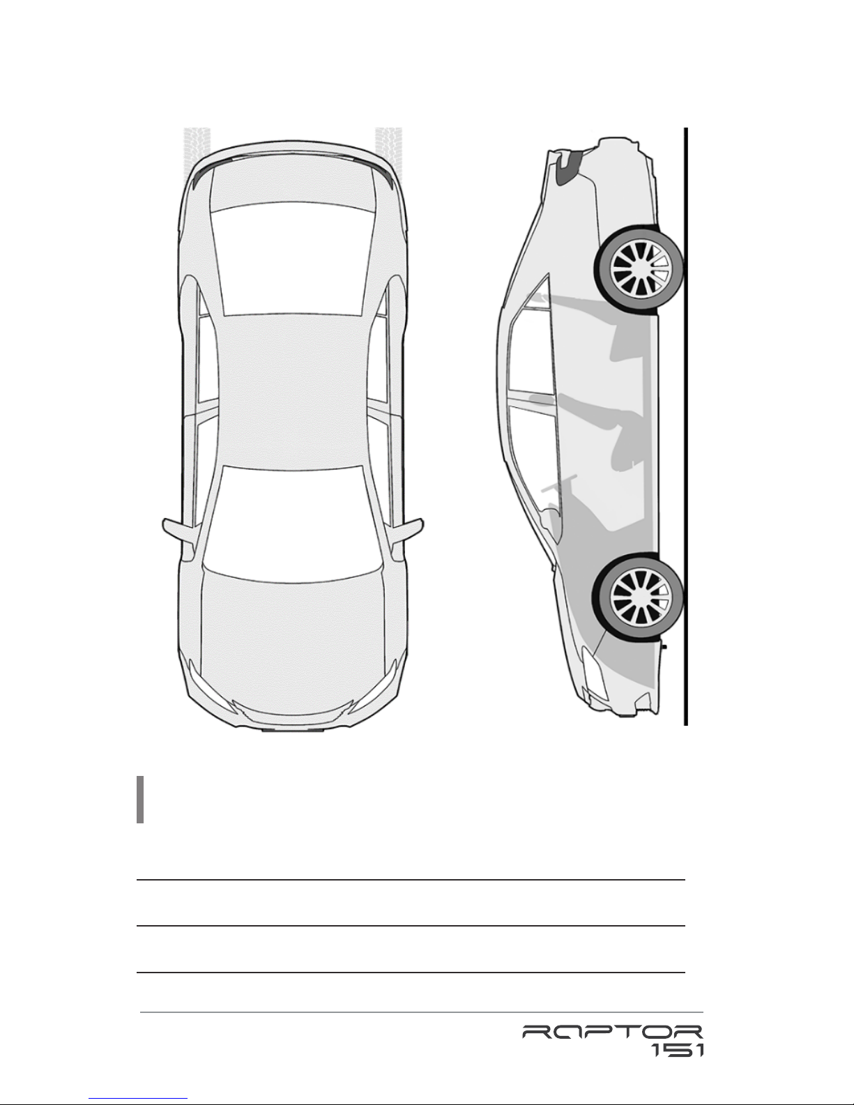
Placement of the locking module
ATTENTION!
Do not leave the plastic card with the code
as well as this guide inside the car!

20
WARRANTY CERTIFICATE
Warranty is 12 months from the date of the purchase. During this
period technical support and maintenance are guaranteed for free.
The warranty does not apply to the items with:
• mechanical damage, burnt and char pieces, components,
conductive tracks etc.;
• traces of an independent repair;
• damage caused by natural hazards, re, social factors;
• violation of the tamper-evident seal, damage or absence of a
factory/trade label.
Only items in complete set and with the original packing are taken for
warranty repair.
Absence of packing is regarded as noncompliance with transportation
rules. The warranty does not apply to the damage incurred to another
equipment operating together with this device.
Item (model) ________________
Sale date ______/____/________
The contents of delivery ___, functioning ___, absence of mechanic
damage ___ are checked.
I am acquainted and agree with the condition of warranty service:
Buyer ______________________________
Seller ___________________________ seal
Table of contents
Other AUTHOR Alarm Car Alarm manuals

AUTHOR Alarm
AUTHOR Alarm Kvant 120 User manual

AUTHOR Alarm
AUTHOR Alarm Kvant 231 User manual

AUTHOR Alarm
AUTHOR Alarm IGLA User manual

AUTHOR Alarm
AUTHOR Alarm IGLA User manual

AUTHOR Alarm
AUTHOR Alarm COMPASS User manual

AUTHOR Alarm
AUTHOR Alarm VOLK User manual

AUTHOR Alarm
AUTHOR Alarm Kord User manual

AUTHOR Alarm
AUTHOR Alarm TOR User manual
Popular Car Alarm manuals by other brands


jablotron
jablotron CA-1803BT Athos installation manual

Clifford
Clifford Cyber 4 owner's manual

Marksman
Marksman Extreme X3 Installation and owner's manual

Scytek electronic
Scytek electronic PRECISION PRO 5500 product manual

Viper
Viper Directed 4706V owner's guide

Audiovox
Audiovox PRO-9342FT3WOS2 installation manual


