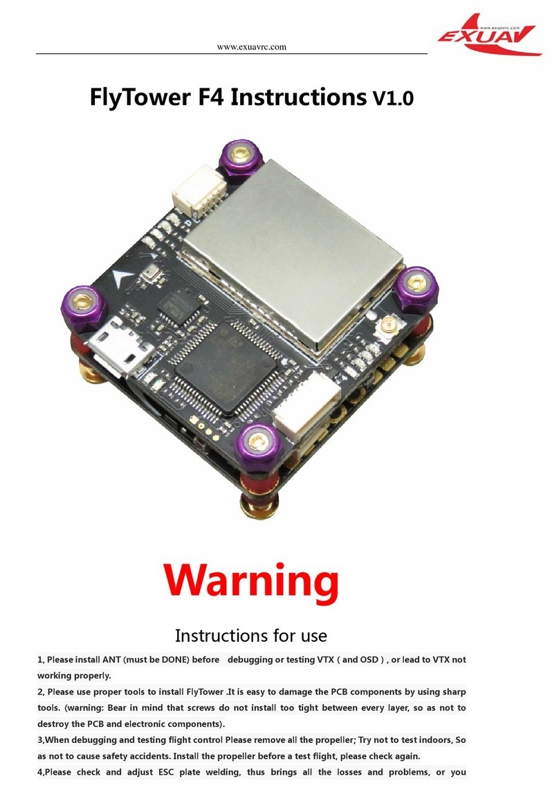
Automation Controls Group UniDrive ZoneLogix PRO User manual

ZoneLogix™ PRO Zone Controller User
Guide
1. Zone 2. Monitor 3. Fieldbus
Guide 1 in the 3-part ZoneLogix™ PRO documentation series
1

Copyright ©2013-2019 Automation Controls Group, Inc. A division of Milwaukee Electronics Companies, Inc. All Rights Reserved.
This document is the property of Automation Controls Group, Inc., and may not be reproduced in whole or in part without prior written approval.
Other trademarks and service marks used or referenced in this document are the property of their respective owners.
C O N T E N T S
1Introduction 6
1.1
Key Terms and Concepts .................................................................................................7
2Getting Started and Installation 8
2.1
Zone Controller Installation ......................................................................................... 10
2.2
Zone Installation ............................................................................................................. 11
2.3
Configuration DIP Switches ......................................................................................... 13
2.4
+24VDC Power Connection.......................................................................................... 14
2.5
Zone-to-Zone Cable Connection ................................................................................. 14
2.6
PNP Photoeye Sensor Connection............................................................................. 15
2.7
Smart I/O Connections ................................................................................................. 16
2.7.1
Basic Mode Functions......................................................................................................................... 16
2.7.2
Advanced Mode Functions................................................................................................................ 17
2.8
LED Feedback Indicators.............................................................................................. 18
2.9
System Schematic and Installation Summary ...................................................... 19
3Basic Mode System Operation & Configuration 20
3.1
System Start Up –Apply 24 VDC Power .................................................................. 20
3.1.1
Zone Discovery ...................................................................................................................................... 20
3.1.2
Lost Package Detection ..................................................................................................................... 20
3.1.3
Sleep Timer............................................................................................................................................. 20
3.2
EOB Zone Configuration................................................................................................ 21
3.2.1
Controlling Object Entry –Forward (normal) Flow Direction................................................. 21
3.3
Master Zone Configuration .......................................................................................... 21
3.3.1
Controlling Object Exit......................................................................................................................... 21
3.3.2
Changing Operational Modes........................................................................................................... 21
3.3.3
Controlling Branch Direction............................................................................................................. 21
3.3.4
Controlling Branch Speed.................................................................................................................. 21
3.4
Basic Mode Parameters ............................................................................................... 21
4Zone Controller Updates 23
5Advanced Mode System Configuration 24
6Motor Performance 25
7Breakout Module 27
7.1
Handshaking Functionality .......................................................................................... 27
7.2
Breakout Module Example: Connect Two Branches............................................ 29
7.3
Breakout Module Example: Connect Two Branches with Branch Monitor.... 29
7.4
Breakout Module Example: Transfer Application................................................. 30

Copyright ©2013-2019 Automation Controls Group, Inc. A division of Milwaukee Electronics Companies, Inc. All Rights Reserved.
This document is the property of Automation Controls Group, Inc., and may not be reproduced in whole or in part without prior written approval.
Other trademarks and service marks used or referenced in this document are the property of their respective owners.
8Diagnostics & Troubleshooting 31
8.1
Feedback LEDs................................................................................................................ 31
8.1.1
Fuse LED (Red) ...................................................................................................................................... 31
8.1.2
Fault LED (Red)...................................................................................................................................... 32
8.1.3
Motor LED (Amber) .............................................................................................................................. 32
8.2
Firmware Version Display............................................................................................. 33
8.3
Additional Assistance.................................................................................................... 33
9Document Revision History 33
Appendix A: Operating Modes 34
A.1. Singulate (ZPA) .................................................................................................................. 34
A.2. Slug ....................................................................................................................................... 34
A.3. ZIP.......................................................................................................................................... 35
A.4. Zone Hold ............................................................................................................................ 35

ZoneLogix™PRO Zone Controller User Guide | Revision 1.0 November 2019 | Page 4
L I S T O F F I G U R E S
Figure 1: The ZoneLogix™ PRO System.....................................................................................6
Figure 2: ZoneLogix™ PRO Zone Controller Diagram ..............................................................8
Figure 3: Zone Controller Mounting Tabs................................................................................ 10
Figure 4: The ZoneLogix™ PRO System.................................................................................. 11
Figure 5: UniDrive Motor Stopping Distance .......................................................................... 12
Figure 6: Default DIP Switch and Smart I/O .......................................................................... 13
Figure 7: Zone-to-Zone Communication Connections .......................................................... 14
Figure 8: LED Definitions........................................................................................................... 18
Figure 9: Schematic Diagram of ZoneLogix™ PRO System................................................. 19
Figure 10: Standard Zone Controller LEDs in Normal Operation........................................ 20
Figure 11: Motor Performance Curves.................................................................................... 25
Figure 12: Breakout Module (Product 300332) .................................................................... 27
Figure 13: Handshaking Signals Showing Forward and Reverse Flow Request / Permission
Signals.......................................................................................................................................... 28
Figure 14: Handshaking Signals Showing Both Forward / Reverse Request / Permission
Signals.......................................................................................................................................... 28
Figure 15: Internal Diagram of the Breakout Module .......................................................... 28
Figure 16: Breakout Module Connecting Two Branches ...................................................... 29
Figure 17: Breakout Module Connecting Two Branches and Branch Monitor.................. 29
Figure 18: Breakout Modules in a Transfer Application....................................................... 30
Figure 19: Feedback LEDs ........................................................................................................ 31
Figure 20: Firmware Version Display Example ...................................................................... 33
Figure 21: Singulate (Singulate Mode) ................................................................................... 34
Figure 22: Slug (Slug Mode)...................................................................................................... 34
Figure 23: ZIP (Operating Mode).............................................................................................. 35
Figure 24: Zone Hold (Singulate, ZIP, and Slug Modes)....................................................... 35

ZoneLogix™PRO Zone Controller User Guide | Revision 1.0 November 2019 | Page 5
L I S T O F T A B L E S
Table 1: DC Power Input Connection....................................................................................... 14
Table 2: PNP Sensor Connection Header ............................................................................... 15
Table 3: Smart I/O Pin Definitions for the EOB Zone Controller ......................................... 16
Table 4: Smart I/O Pin Definitions for the Standard Zone Controller ................................ 16
Table 5: Smart I/O Pin Definitions for the Master Zone Controller in Basic Mode .......... 17
Table 6: Operating Modes for Smart I/O Pins 1 & 2 on the Master Zone Controller in Basic
Mode............................................................................................................................................. 17
Table 7: Speed Input Analog Control....................................................................................... 17
Table 8: Parameters in Basic Mode......................................................................................... 22
Table 9: Fault LED ...................................................................................................................... 32
Table 10: Motor Current LED .................................................................................................... 32

ZoneLogix™PRO Zone Controller User Guide | Revision 1.0 November 2019 | Page 6
1
Introduction
The ZoneLogix™ PRO Smart Conveyor System is a product that is used in material handling conveyance
applications. The system is comprised of two main components: Zone Controllers and the Branch
Monitor. A typical application consists of some length of roller conveyor (a Branch), divided into zones.
Each zone has a Zone Controller that controls a Brushless DC (BLDC) motor, or solenoid air actuator.
Zone Controllers communicate via a high-speed network. The Branch Monitor provides three different
functions: (1) It acts as a system monitor to allow for monitoring the operation of the Branch, (2) it acts
as a device to configure the behavior of the individual zones, and (3) it provides an EtherNet/IP fieldbus
interface for use with a Programmable Logic Controller (PLC).
ZoneLogix™ PRO was designed to provide levels of operation ranging from basic speed and direction to
advanced sophisticated implementations.
▪Basic Mode: Everything your smart conveyor system needs to get started is already built-into the
ZoneLogix™ PRO system. You can connect up to 255 package-handling segments, or zones, in series
with one UniDrive®motor per zone.
▪Advanced Mode: By adding the ZoneLogix™ PRO Branch Monitor, you can configure each individual
zone according to the needs of the application. Optionally, you can also connect a PLC to further
leverage the networking power of the ZoneLogix™ PRO to provide automated package tracking and
sophisticated control capabilities. You can connect up to 120 zones in a Branch. Multiple Branches
can be connected to each other.
Figure 1: The ZoneLogix™ PRO System

ZoneLogix™PRO Zone Controller User Guide | Revision 1.0 November 2019 | Page 7
1.1
Key Terms and Concepts
▪Branch: A conveyor section that consists of a series of zone controllers with a defined entry End-of-
Branch (EOB) zone (upstream), and an exit Master zone (downstream) {in the Forward (normal) flow
direction}. In between the EOB and Master are Standard zones.
NOTE: A Branch requires a minimum of (1) EOB and (1) Master
▪Forward (normal) Flow Direction: Transportation from EOB (entry) to Master (exit)
▪Reverse Flow Direction: Transportation from Master (becomes entry) to EOB (becomes exit)
▪End-of-Branch (EOB): The EOB is the entry to the Branch in the Forward (normal) Flow Direction
▪Master: The Master zone controller is the exit zone of the Branch in the Forward (normal) flow
direction. It communicates the modes of operation to all zone controllers in the Branch. You can
configure the Master in Basic Mode or Advanced Mode.
▪Standard: Zone controllers that are located between the EOB and Master
▪Branch Monitor:The Branch Monitor provides a user interface display, and pushbuttons to configure
a Branch. The Branch Monitor helps you gather information about the Branch and configure it for
your needs.
▪Primary Sensor: Photoeye input for the downstream edge of a zone, when configured for the
Forward (normal) flow direction.
▪Secondary Sensor: Photoeye input for the downstream edge of a zone, when configured for the
Reverse flow direction.
▪Smart I/O: General purpose, 24 VDC I/O, that can be used as an extension of a PLC, or configured to
one of several built-in functions.
▪Analog Speed Input: Allows a zone to be controlled via a 0-10 VDC signal
▪Basic Mode: Basic Mode is the out of the box solution for ZPA. It uses discrete signals to control
several parameters for Branch configuration (a Branch Monitor is not required). A Branch may contain
up to 255 zones.
▪Advanced Mode: Advanced Mode utilizes the full power of the Branch Monitor to individually
configure each zone in a Branch. Optionally, the EtherNet/IP fieldbus connection may be used to
control a Branch via a Programmable Logic Controller (PLC). A Branch may contain up to 120 zones.
▪Branch Serial Communications: Serial communications that allows the Master to configure all
zones within a Branch (Master-to-Zones)
▪Handshake Communications: Request, Permission, and Sensor signals that pass between adjacent
zones. Allows for zone-to-zone communication for handling package flow.
▪Protective Extra Low Voltage (PELV): IEC 61140 defines a PELV system as an electrical source in
which the voltage cannot exceed 30 Vrms or 60 VDC under normal or single-fault conditions, and its
DC common (minus (-) output terminal) is connected to earth ground.

ZoneLogix™PRO Zone Controller User Guide | Revision 1.0 November 2019 | Page 8
2
Getting Started and Installation
Below is an image of the Zone Controller and the various connections. In Basic Mode there are a few
operational mode settings that can be made via Smart I/O settings which are described later in this
manual. To configure a system in Advanced Mode, see Section 5: Advanced Mode System
Configuration.
Figure 2: ZoneLogix™ PRO Zone Controller Diagram
1) Secondary Sensor: Photoeye input for the downstream edge of a zone, when configured for the
Reverse flow direction.
a. Phoenix Contact, 3-pos plug, 1881338
2) To EOB Communication: This is meant to only connect to the “To Master” connection of
another Zone Controller. Zone Controllers are intended to be daisy chained together in a series.
a. RJ45, 8P8C, CAT5 (or better), Ethernet cable

ZoneLogix™PRO Zone Controller User Guide | Revision 1.0 November 2019 | Page 9
3) Smart I/O: General purpose, 24 VDC I/O, that can be used as an extension of a PLC, or
configured to one of several built-in functions
a. Phoenix Contact, 4-pos plug, 1881341
4) UniDrive®Motor Connection: Motor connection for any UniDrive®Brushless DC Motor. The
motor contains this plug. It is listed here for reference.
a. Motor Input: Molex, 10-pos plug, 172258-1110
5) Primary Sensor: Photoeye input for the downstream edge of a zone, when configured for the
Forward (normal) flow direction.
a. Phoenix Contact, 3-pos plug, 1881338
6) To Master Communication: This is meant to only connect to the “To EOB” connection of
another Zone Controller. Zone Controllers are intended to be daisy chained together in a series.
a. RJ45, 8P8C, CAT5 (or better), Ethernet cable
7) Smart I/O: General purpose, 24 VDC I/O, that can be used as an extension of a PLC, or
configured to one of several built-in functions
a. Phoenix Contact, 4-pos plug, 1881341
8) Power Input: 24 VDC power input
a. Molex, 2-pos plug, 172256-1002
9) DIP Switches: Configures various modes and functions of the Zone Controller

ZoneLogix™PRO Zone Controller User Guide | Revision 1.0 November 2019 | Page 10
This section describes how to install the ZoneLogix™ PRO and UniDrive®motors in the most common
configuration.
2.1
Zone Controller Installation
Mount the Zone Controller in a location where the motor cable reaches the connection header without putting strain
on the cable connector or the header. The Zone Controller can mount to the conveyor frame using two ¼ inch (0.25
in or 6.35 mm) bolts.
CAUTION: If mounting the control on a curved section of conveyor, use washers between the mounting plate and the conveyor
frame. This is to assure that the mounting plate is not distorted, causing damage to the enclosed printed circuit board assembly.
Figure 3: Zone Controller Mounting Tabs
CAUTION: Removal of the cover will void the warranty. The cover does not make the controller waterproof or dustproof.
1. Zone Controller Installation
2. Motor Installation
3. DIP Switch Settings
4. Cable Connections
5. System Configuration
6. Diagnostics & Troubleshooting

ZoneLogix™PRO Zone Controller User Guide | Revision 1.0 November 2019 | Page 11
2.2
Zone Installation
A typical zone is installed as shown below.
Figure 4: The ZoneLogix™ PRO System
•The motor is typically placed in the middle of the zone
•The Primary Sensor is used as the zone photoeye sensor input when package flow is left to right (Forward
Direction EOB to Master)
•The Secondary Sensor is used as the zone photoeye sensor input when package flow is right to left (Reverse
Direction Master to EOB)
•The photoeye sensor should be a 24 VDC PNP, where the output is 24 VDC when a package is detected
•The recommended photoeye sensor placement is typically ~6” at <30 m/min, with respect to the
downstream edge of the zone. The sensor position is determined by factors such as the speed and weight of
the object. Heavier loads at higher speeds require greater distance to stop moving.
•Maximum load current of the photoeye sensor should be <150 mA
•Mount the control where there is adequate heatsink and no strain on the cable connections

ZoneLogix™PRO Zone Controller User Guide | Revision 1.0 November 2019 | Page 12
Figure 5: UniDrive Motor Stopping Distance

ZoneLogix™PRO Zone Controller User Guide | Revision 1.0 November 2019 | Page 13
2.3
Configuration DIP Switches
The DIP switches are used to configure the zone type and motor rotation direction in the Forward (normal) flow
direction (EOB to Master).
NOTE: The DIP switches are read during power-up only. Set the switches, and then apply power to the Zone Controller.
Figure 6: Default DIP Switch and Smart I/O
NOTE: The direction of rotation is defined as viewed from the back side of the motor with the shaft extending away from the viewer.

ZoneLogix™PRO Zone Controller User Guide | Revision 1.0 November 2019 | Page 14
2.4
+24VDC Power Connection
CAUTION! Power must be applied with proper polarity to avoid potentially damaging the Zone Controller. Follow the pinout shown
in Table 1 below.
The ZoneLogix™ PRO operates from +22 to +28 volts DC power. Make the power connection only after all other
connections have been made.
Table 1: DC Power Input Connection
Pin:
Signal:
0VDC
DC Ground
24VDC
+22 to +28 VDC, PELV
IMPORTANT! When adjacent zones are operating from separate power supplies, connect their DC grounds. However, do not
connect their positive voltage pins together. The positive voltage differential should be < 4 VDC.
2.5
Zone-to-Zone Cable Connection
The controls pass Branch Serial Communications and Handshaking signals between adjacent zones over standard
Ethernet cables. The To EOB connector must be connected to the To Master connector of an adjacent upstream unit.
The To Master connector must be connected to an adjacent downstream unit using its To EOB connector. When
connecting two branches together, see Section 7: Breakout Module.
Figure 7: Zone-to-Zone Communication Connections
CAUTION! Do not cross wiring of the
Ethernet cables. The left side of the zone
must connect to the adjacent zone on the
left, and the right side of the zone must
connect to the adjacent zone on the right.
Zones should be connected as shown above.

ZoneLogix™PRO Zone Controller User Guide | Revision 1.0 November 2019 | Page 15
2.6
PNP Photoeye Sensor Connection
Each zone requires an object sensor to detect the objects that are in the zone when they reach the most downstream
edge of the zone. In the Forward (normal) flow direction, the Primary Sensor is the downstream sensor. In
applications where the conveyor is run in Reverse Flow, the Secondary Sensor then becomes the most downstream
sensor. Wire the leads of the sensor to the appropriate terminals on the Sensor Connection Header.
CAUTION! If the sensor is mounted on non-conductive equipment, such as a plastic slide, ground the body of the sensor to provide a
non-destructive discharge path in the event of a static electric shock.
Table 2: PNP Sensor Connection Header
Pin
Notes:
Signal In
PNP sensor input with maximum loading of <150 mA. This input must be 24VDC (active high) when an object blocks
the sensor.
0VDC
DC Ground (See CAUTION above)
24VDC
Sensor power. Use of this output for any purpose that requires more than 150 mA will cause the self-resettable
fuse to open and temporarily remove 24VDC power to the sensor.

ZoneLogix™PRO Zone Controller User Guide | Revision 1.0 November 2019 | Page 16
2.7
Smart I/O Connections
The function of each PNP pin depends on the configuration of the Zone Controller. See 2.3 Configuration DIP
Switches. Additional functions are available in Advanced Mode.
2.7.1 Basic Mode Functions
The following functions only apply when the Master Zone Controller DIP switch settings are configured for Basic
Mode.
IMPORTANT! All Smart I/O inputs and outputs except analog are PNP only and are active at 18 VDC or higher. The maximum
current available per output is 500 mA.
Table 3: Smart I/O Pin Definitions for the EOB Zone Controller
I/O Pin:
Description:
1
Zone Hold In
2
Not Defined
3
Motor Running Out
4
Forward Request/Reverse Permission In
5
Forward Permission/Reverse Request Out
6
Zone No-Fault Out
Speed In
Zone Speed (0-10 VDC Analog In)
Table 4: Smart I/O Pin Definitions for the Standard Zone Controller
I/O Pin:
Description:
1
Zone Hold In
2
Local Speed Inhibit In
3
Motor Running Out
4
Forward Permission/Reverse Request In
5
Forward Request/Reverse Permission Out
6
Not Defined
Speed In
Zone Speed (0-10 VDC Analog In)

ZoneLogix™PRO Zone Controller User Guide | Revision 1.0 November 2019 | Page 17
Table 5: Smart I/O Pin Definitions for the Master Zone Controller in Basic Mode
I/O Pin:
Description:
1
Branch Op Mode 1 In
2
Branch Op Mode 2 In
3
Branch Reverse In
4
Forward Permission/Reverse Request In
5
Forward Request/Reverse Permission Out
6
Branch No-Fault Out
Speed In
Branch Speed (0-10 VDC Analog In)
Table 6: Operating Modes for Smart I/O Pins 1 & 2 on the Master Zone Controller in Basic Mode
Branch Op Mode 1 In
Branch Op Mode 2 In
Branch Operation
Inactive
Inactive
Singulate (ZPA)
Active
Inactive
ZIP
Inactive
Active
Slug
Active
Active
Disable
Table 7: Speed Input Analog Control
Voltage
Operation
<0.5 VDC
Zone operates at configured speed
0.5 to 9.0 VDC
Zone speed is proportional to the input within the
full range of the motor selected
>9.0 to 24 VDC
Zone operates at full speed
2.7.2 Advanced Mode Functions
See the companion ZoneLogix™ PRO Branch Monitor User Guide for further information about Advanced Mode
functions.

ZoneLogix™PRO Zone Controller User Guide | Revision 1.0 November 2019 | Page 19
2.9
System Schematic and Installation Summary
The following is a system schematic and summary of settings:
Figure 9: Schematic Diagram of ZoneLogix™ PRO System
•A Branch is made up of at least (1) EOB and (1) Master
•Forward (normal) package flow is from EOB to Master. See 3.3.3 Controlling Branch Direction for instructions
to reverse the flow direction.
•Standard Zone Controllers are placed between EOB and Master
•Identify the Zone Controller location in the Branch, and set the DIP switches as noted above
•Identify the proper direction of rotation for each motor to move packages from the upstream (entry) end of
the conveyor to the downstream (exit) end (EOB to Master); may depend on motor mounting orientation.
•Connectors/Plugs:
oPhotoeye Sensors: Phoenix Contact, 3-pos plug, 1881338
oSmart I/O: Phoenix Contact, 4-pos plug, 1881341
oPower Input: Molex, 2-pos plug, 172256-1002
oMolex Crimping Tool: Molex, 20-22 AWG tool, 0638275400
oMolex Crimp Terminals: Molex, 20-22 AWG terminals, 172253-3123
oMolex Crimping Tool: Molex, 16-18 AWG tool, 0638275300
oMolex Crimp Terminals: Molex, 16-18 AWG terminals, 172253-3023
oCommunication Cables: Standard CAT5, or better, RJ45 Ethernet cables
CAUTION! Power must be applied with proper polarity to avoid potentially damaging the Zone Controller.
CAUTION! Do not cross wiring of the Ethernet cables. The left side of the zone must connect to the adjacent zone on the left, and the
right side of the zone must connect to the adjacent zone on the right. Zones should be connected as shown above.
IMPORTANT! When adjacent zones are operating from separate power supplies, connect their DC grounds. However, do not
connect their positive voltage pins together.
NOTE: The direction of motor rotation is defined as viewed from the back side of the motor with the shaft extending away from the
viewer.
NOTE: The DIP switches are read during power-up only. Set the switches, and then apply power to the Zone Controller.

ZoneLogix™PRO Zone Controller User Guide | Revision 1.0 November 2019 | Page 20
3
Basic Mode System Operation & Configuration
3.1
System Start Up –Apply 24 VDC Power
3.1.1 Zone Discovery
When powered on, the Master Zone Controller initiates a Branch discovery process. The Master communicates
sequentially to upstream Zone Controllers and initializes each zone. Each zone should have the following LEDs
illuminated:
•The Pwr LED should be illuminated solid
•The EOB Zone Controller should have the Down comm LED illuminated solid
•The Master Zone Controller should have the Up comm LED illuminated and the Down comm LED will blink
at a ½ second rate only when the optional Branch Monitor is connected.
•All Standard Zone Controllers should have the Up and Down comm LEDs illuminated solid
NOTE: When illuminated, the Up comm LED indicates a good connection to the zone on the left. The Down comm LED indicates a
good connection to the zone on the right.
•Check all photoeye sensors to ensure the indicator LEDs are illuminated correctly (see manufacturer’s manual)
Figure 10: Standard Zone Controller LEDs in Normal Operation
3.1.2 Lost Package Detection
During power up, beginning at the exit end and then flowing zone-by-zone after very brief intervals to avoid creating
high inrush current at the power supply, each zone then runs for up to the value of the Sleep Timer (default is 5
seconds) or until an object arrives at the respective zone sensor, whichever comes first. This process will ‘find’ objects
that may have been stranded between zone sensors if power was removed while an object was being transported.
3.1.3 Sleep Timer
A zone will run for up to the value of Sleep Timer (default is 5 seconds) until either an object arrives at the zone sensor,
or until the timeout expires. The purpose of this functionality is to ensure that an object is not stranded between
sensors.
This manual suits for next models
1
Table of contents
Popular Controllers manuals by other brands
Lattice Semiconductor
Lattice Semiconductor MachXO2 Series Programming and Configuration Usage Guide
Danfoss
Danfoss AFPQ 2 operating guide

Progres
Progres AGRONIC 5500 Installation
Full Gauge
Full Gauge PCT-400R Plus manual
Spirax Sarco
Spirax Sarco PN9120 Installation and maintenance instructions
Epever
Epever EPIPDB-COM-10 user manual

