WARNING: This proced re sho ld only be performed by q alified personnel who are experienced in working with electronic eq ipment. Take the necessary steps to
prevent damage from static electricity discharge. Disconnect inp t power to the to ch panel before proceeding. Be caref l not to pinch the ribbon cable between
the ho sing and bezel when re-assembling the panel.
Preparation: Disconnect input power and all other connections, then remove the touch panel from the control cabinet. In a clean environment, place the panel face
down on a lint-free soft surface to prevent scratching the front of the panel.
w w w . a u t o m a t i o n d i r e c t . c o m / c - m o r e
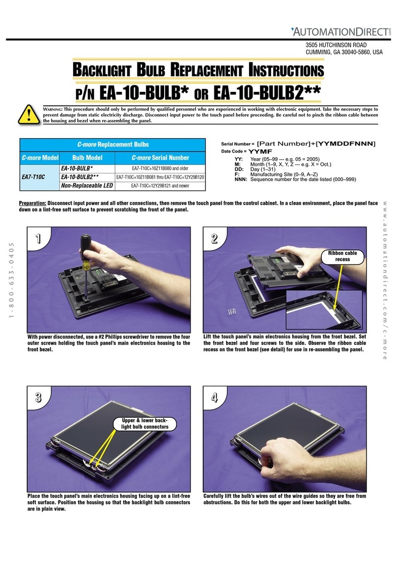
ith power disconnected, use a #2 Phillips screwdriver to remove the four
outer screws holding the touch panel’s main electronics housing to the
front bezel.
Lift the touch panel’s main electronics housing from the front bezel. Set
the front bezel and four screws to the side. Observe the ribbon cable
recess on the front bezel (see detail) for use in re-assembling the panel.
1 - 8 0 0 - 6 3 3 - 0 4 0 5
Carefully lift the bulb’s wires out of the wire guides so they are free from
obstructions.
Place the touch panel’s main electronics housing facing up on a lint-free
soft surface. Position the housing so that the backlight bulb connector is
in plain view. (There is only one bulb used on the 12” touch panel.)
BACKLIGHT BULB REPLACEMENT INSTRUCTIONS
P/NEA-12-BULB* OR EA-12-BULB2**
3505 HUTCHINSON ROAD
CUMMING, GA 30040-5860, USA
22
22
11
11
33
3344
44
Ribbon cable
recess
Lower backlight
bulb connector
YYMF
YY: Year (05–99 --- e.g. 05 = 2005)
M: Month (1–9,X, Y,Z--- e.g. X= Oct.)
DD:Day(1–31)
F: Manufacturing Site (0–9,A–Z)
NNN:Sequence number for the date listed(000–999)
Serial Number =
[PartNumber]+[YYMDDFNNN]
DateCode=
C-more Replacement Bulbs
C-more Model Bulb Model C-more Serial Number
EA7-T12C
EA-12-BULB* EA7-T12C+10Z29B019 and older
EA-12-BULB2** EA7-T12C+10Z29B020 thru EA7-T12C+14102B060
Non-Replaceable LED EA7-T12C+14102B061 and newer
