AutoMeter BusPro Series User manual

Professional
BusPro Series
Instruction Manual
2650-505X-10
Rev. E
Test Equipment
Auto Meter Products Inc.
413 West Elm Street
Sycamore, IL 60178
Toll Free (866) 883-TEST (8378)
Fax (815)-895-6786
www.autometer.com
12

BUSPRO SERIES
SPECIFICATIONS
Charges ------------------------------------------------------ 12 Volt Batteries
Input------------------------------------------------------- 110 VAC @ 5 Amps
Charging output mode----------------------------------------- 5 Amps Max.
Maintenance output mode----------0 to 2.5 Amp variation as needed
Leads ---------------------------------------------------------------- 6 ft. 18 GA.
Size ------------------------------------ BusPro 600 - 26” W 8” H 3.25” D
-------------------------------------------- BusPro 300 - 14” W 8” H 3.25” D
Weight ---------------------------------------------------31 lbs. - BusPro 600
-------------------------------------------------------------17 lbs. - BusPro 300
Optional AC-8 Jumper Leads ------------------------------------- Set of six
CONTENTS
Safety Instructions----------------------------------------------------------- 3
Personal Safety -------------------------------------------------------------- 4
Setting Up the Charger----------------------------------------------------- 5
Inspecting The Battery------------------------------------------------------ 6
Hooking up the Clamps ---------------------------------------------------- 7
Reading the Indicator Lights --------------------------------------------6-7
Disconnecting the Charger ------------------------------------------------ 8
Hookup Potential (3 units together and optional leads) ------------ 9
What to Expect from your Charger -------------------------------------10
Warranty and Service Information -------------------------------------- 11
Contact Information --------------------------------------------------------12
LIMITED WARRANTY
12 MONTHS FROM DATE OF PURCHASE
CABLES 90 DAYS
The manufacturer warrants to the consumer that this product
will be free from defects in material or workmanship for a pe-
riod of twelve (12) months from the date of original purchase.
Products that fail within this 12 month warranty period will be
repaired or replaced at the manufacturer's option to the consum-
er, when determined by the manufacturer that the product failed
due to defects in material or workmanship. This warranty is
limited to the repair or replacement of parts and the necessary
labor by the manufacturer to effect the repair or replacement of
the product. In no event shall the manufacturer be responsible
for special, incidental or consequential damages or costs in-
curred due to the failure of this product.
Improper use, accident, water damage, abuse, unauthorized
repairs or alterations voids this warranty. The manufacturer
disclaims any liability or consequential damages due to breach
of any written or implied warranty on its test equipment.
WARRANTY AND SERVICE INFORMATION
Warranty claims to the manufacturer's service department must
be transportation prepaid and accompanied by a dated proof of
purchase. This warranty applies only to the original purchaser
and is non-transferable. Freight damage incurred during return
shipments is not covered under this warranty. It is the respon-
sibility of the shipper (the customer returning the Test Equip-
ment) to package the tester properly to prevent any damage
during return shipment. Repair costs for such damages will be
charged back to shipper (customer returning the Test Equip-
ment). Protect the product by shipping in original carton or add
plenty of over-pack cushioning such as crumpled up newspaper.
For Service Please Contact:
Auto Meter Products, Inc.
413 West Elm Street
Sycamore, IL 60178
Phone: 866-883-8378
Fax: 815-895-6786
test_service@autometer.com
2
11

SAFETY INSTRUCTIONS
WARNING:
Lead Acid Batteries are Dangerous! During use and charging they
may generate EXPLOSIVE Hydrogen Gas. This means YOU MUST
carefully read all of the safety and operating instructions before using
the chargers. Be sure you understand all of the safety instructions in
this manual before attempting to connect, charge, or work with a lead
acid battery.
What To Expect From Your BusPro Charger
The Professional Charger is equipped with sophisticated circuitry that will:
n Check Each Battery’s Condition The charger will indicate bad batteries
that are sulfated or have bad cells. This allows the battery to be replaced
without unnecessary charging.
n Every Station Can Fully Charge One 12 volt Batteries (5 Amps. each).
With the optional Jumper Lead Kit the BusPro 600 can charge up to twelve
batteries at 2.5 Amps each and the BusPro 300 can charge up to six.
n Maintain Each Battery The charger provides a separate charging station for
each battery.
n Provide Worry Free Attention The charger has safe circuitry that
automatically adjusts the volt/current relationship in order to maintain the
battery at full charge. If the voltage drops below 12.5 volts, the charger
will automatically charge the battery with up to 5 Amps. When the battery
reaches the threshold again the unit goes into maintenance mode.
n Maximize Battery Life The charger is designed to maximize the life of a
serviceable lead acid battery. A serviceable battery is a battery that is not
defective or damaged. The charger is fully compatible with gelled electrolyte
(gel-cell) batteries (sometimes used in place of liquid electrolyte batteries in
many heavy duty applications). DO NOT USE WITH DRY CELL, NICKEL
CADMIUM, and NICKEL METAL HYDRIDE OR SIMILAR BATTERIES.
n Increase Multiple Battery Charging Capability The charger provides the
opportunity to charge more batteries with less time spent charging defective
batteries that need to be replaced.
n Provide Valuable Protection The charger maintains batteries while they
are un-installed. Maintaining a battery increases its life and protects its
capacity.
n Maintain Batteries Not In Use. Some examples are automobiles under
long term repair, farm machinery and eet vehicles in repair or storage.
The charger is ideal for rental equipment not in use or for charging and
maintaining batteries for replacement. The charger can be used to re-
charge, check and maintain all starting and deep cycle batteries.
n Provide Easy Care The charger is designed for easy care and
maintenance. Occasional cleaning of the leads and housing will help keep
the unit looking new, and give you many years of satisfaction. CLEANING
PROCEDURE: Unplug the charger and use a slightly dampened cloth to
clean the housing and lead sets. DO NOT use solvents or soaps.
n Provide Long Lasting Performance The charger has been designed
and manufactured to provide superior performance. Quality is built in and
assured with circuit burn-in, computerized testing and inspection.
n Fuse Protected Each charging station is protected by a replaceable AC
fuse.
GENERAL SAFETY RULES FOR SAFE OPERATION
Batteries are dangerous. Auto Meter provides the following Warnings for
your safety:
1. Use the charger only on 12 Volt LEAD ACID, AGM Batteries and GELLED
ELECTROLYTE (GEL-CELL) Batteries. DO NOT attempt to use on other
types of batteries (Dry Cell, Nickel Cadmium, Nickel Metal Hydride, etc.)
commonly found in small home appliances. This may cause the batteries to
burst, resulting in damage or injury to person and/or property.
2. DO NOT use the charger on batteries that are in use or that are installed.
3. DO NOT use attachments with the charger that are not approved or sold by
manufacturer. Non-approved attachments may result in injury, electric shock,
or re and voids the warranty.
4. When disconnecting the power cord from the wall, grasp the plug and pull.
Never pull the cord, it may damage the plug and/or the cord.
5. Place the power cords in a location where they will not be stepped on,
tripped over, or subjected to stress or abuse of any kind.
6. Never operate the charger if any portion of its housing, cords or attachments
appear to be damaged in any way. If damage has occurred, have it
inspected and serviced by the manufacturer.
7. If the charger has been dropped, received a sharp blow, or abused in any
way, have it inspected and repaired by the manufacturer if necessary.
8. Do not use an extension cord to operate the charger. An inadequate
extension cord could result in re or explosion due to a large number of
batteries being charged and will not provide the AC amperage rating needed
by the charger.
9. Each charging Station has its own AC fuse. Other than this fuse
replacement, the manufacturer should be contacted for trouble shooting
and instructions on how to repair or replace parts and charging stations.
Any unauthorized repair, tampering or incorrect assembly may result in re
or electric shock and voids the warranty. Check with the manufacturer for
instructions.
10. To prevent injury during cleaning or maintenance, disconnect all batteries
and move them away from the unit. Unplug the charger from the wall outlet
(grasping the plug). Use a slightly dampened cloth to clean the housing and
lead sets. Do not use solvents or soaps.
10
3
11. NEVER attempt to charge a frozen battery. Allow the battery to return to
room temperature before connection.
12. ALWAYS use the charger in an open and well-ventilated area. The area
should be dry and free of trash, debris and combustibles.
13. WARNING! Explosive Hydrogen gas may be present around batteries.
14. Do not use the charger in direct sunlight or adverse weather conditions such
as rain or snow.
15. Mount the charger on a secure wall location at least two feet above the
batteries being charged. This prevents acid drips and spills from landing on
the charger during battery lling or specic gravity testing. This also prevents
battery fumes from reaching the charger.
16. Do not place small objects or tools on the top edge of the mounted unit.
17. NEVER use the charger in or on any boat or watercraft. You must remove
the battery from the boat or watercraft and charge the battery at the properly
installed location of the charger unit.
18. DO NOT install the charger where it will be exposed to moisture, inclement
weather nor around combustibles, ammable liquids or vapors and
trash.
SAFETY INSTRUCTIONS Cont.
PERSONAL SAFETY PRECAUTIONS
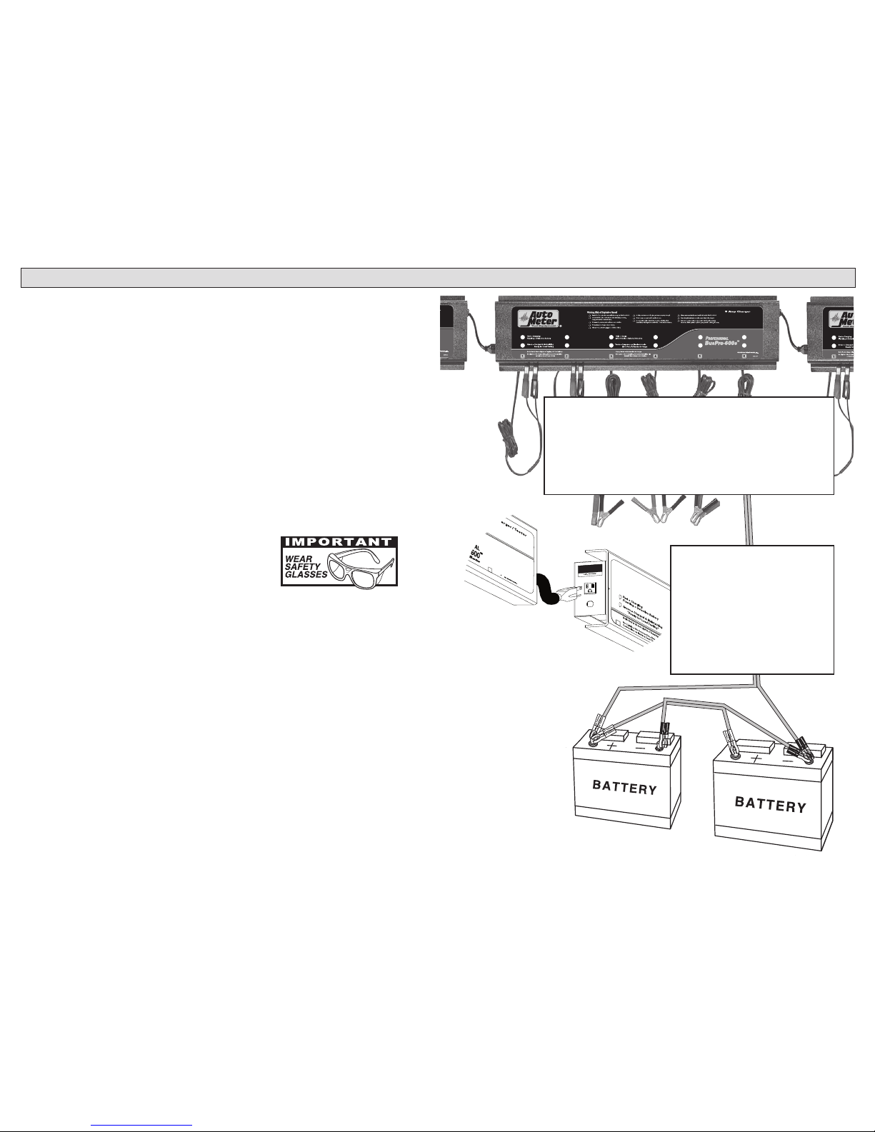
BusPro Charger HOOKUP POTENTIAL
Charge up to 36 12-Volt batteries with the BusPro 600
Charge up to 18 12-Volt batteries with the BusPro 300
1. Wear protective goggles or a full-face shield.
2. Wear protective clothing. Leave no exposed skin.
3. Have plenty of fresh water and hand soap available for use if acid should
contact your eyes, skin or clothing.
4. Have someone close by in the event you need emergency assistance when
working with a battery.
5. Remove all metal objects (pens, tools, jewelry, etc.) from your body. These
items can create a direct short between the battery terminals and can cause
serious burns.
6. DO NOT carry tools or metal objects within the vicinity of a battery. These
items can fall on the battery terminals creating a high current short. This
could result in a re, burns, explosion, etc.
7. DO NOT touch your face, eyes or other body parts with out rst washing
your hands. Battery acid can burn and irritate eye and skin tissue.
8. DO NOT allow any source of ignition in the area of a battery. Keep all ame
and spark producing devices out of the area and NEVER SMOKE near a
battery.
9. Use the one hand rule! Keep one hand in your pocket whenever you make
an electrical connection. This reduces the risk of electrical shock to the user.
n Each station delivers 5 Amps to one battery
n With optional AC-8 lead sets each station
delivers 2.5 Amps to each battery
n In order to charge multiple batteries per
station follow the steps below:
Using optional AC-8 sets
hookup two 12 Volt
batteries in parallel
to each station
of the charger
as shown.
Note: If red light
ashes detach
one battery to
determine which
battery is defective
Recommended for
maintenance only or comparable
batteries in size and state of charge.
Step 2 Using the
Optional Lead Sets
Step 1 Hooking Up 3 Units
Mac Tools,Inc.
Columbus, OH 43228
MacTools, Inc.
Columbus, OH 43228
2007
Hook 3 units together by
plugging the next unit into the
AC plug provided on the left end
of the charger. Make sure the
power source supplied to the
rst charger is adequate.
A typical 120 Volt outlet will only
supply 3 units.
4
9
1SETTING UP THE BusPro Charger
The charger has two mounting keyholes. YOU MUST mount the charger
to a wall that provides a secure surface. This will keep it out of the way
and prevent damage due to accidents. If needed, you may leave the two
screws slightly extended from the wall to allow easy removal through the
keyhole slots.
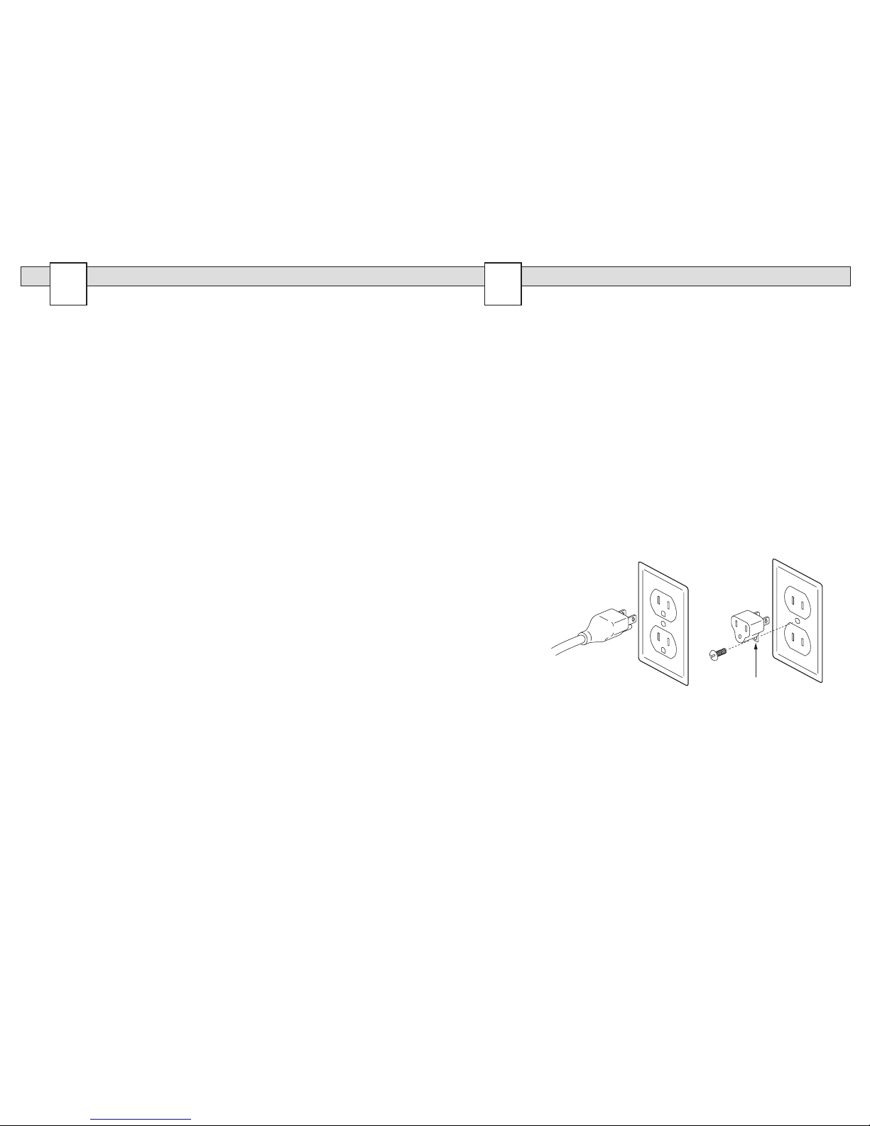
Connect the
charger to a grounded
120-Volt AC power receptacle
that is wired in compliance with local
electrical codes. If you do not know how to test a receptacle for proper
ground, have a qualied electrician test it for you. A grounded receptacle
will receive a plug with a round ground pin and two blade terminals.
If the outlet will not receive a plug with a ground pin, you will need a
temporary-ground adapter with a metal grounding tab shown to the right.
Be sure the metal ground tab is securely screwed into the faceplate as
shown. Use this adapter only as a temporary means of connection. Have
a qualied electrician install a proper receptacle as soon as possible.
WARNING! Do not alter the plug or cord on the charger. Any alterations
will void the warranty.
5DISCONNECTING THE BusPro Charger
The charger is safely maintaining the battery at a full charge when the
green light is on. Simply remove the clamps and set them on the working
surface clear from the other batteries and clamps. You can now load-test
the battery.
Note: When the clamps are accidentally disconnected while charging
is in effect the charger will shut the individual station off. Both indicator
lights will go out. Simply reconnect the battery.
Note: The charger is designed to send a 5 amp charge only when the
circuitry determines the clamps have been attached correctly and the
battery is in need of charging. Under normal operation the clamps will not
cause any sparks if the black (-) and red (+) come in contact or if any clip
comes in contact with another.
Caution: BATTERIES ARE DANGEROUS! Be sure to practice these
proper safety rules when connecting and disconnecting batteries from
the BusPro Charger:
n Wear safety glasses.
n Make sure no sparks occur such as an engine starting etc.
n Make sure no tools or metal objects are in the vicinity of the
batteries
n Connect clips to a clean, properly inspected battery
n Do not disconnect a battery while charging. Wait for the green
light (OK) or ashing red (Defective).
n Handle clips carefully and set them from safely aside other
batteries and clamps.
Caution: In determining placement of the charger check the following:
n Make sure the batteries can be placed at least two feet away. For
example, If the batteries are placed on the oor make sure the
charger is mounted securely at least two feet above, but no
more than the working length of the leads.
n Make sure the room has plenty of ventilation.
n Make sure no sparks or ames can occur near the charging area.
n Mount the charger away from vehicle repair or service area.
n Never start or run an engine near the batteries being charged. It
takes very little to ignite explosive gases given off by a lead-acid
battery. Remember: You may be charging several batteries at a
time. This compounds the need for a strict safety program.
See page 9 for hooking up three charger units together.
8
5
PROPER
AC POWER
CONNECTIONS
Metal
Grounding Tab

PC600s
Manufactured by:
P
ROFESSIONAL
2INSPECTING THE BATTERY
Remove and Inspect the battery before connecting it to a the charger.
A clean battery and battery terminals insure proper operation of the
charger and the vehicle charging system.
3HOOKING UP THE CLAMPS
Each charging station has a lead set with a red positive (+) and a black
negative (-) clamp. If the charger has been installed correctly, at least two
feet above the work station, the clamps should lie on a clean dry surface.
n Check for dirty or loose terminals.
n Check for any cracks or distortion in the battery case.
n Make sure the battery is the correct group size and capacity for the
vehicle.
n Make sure the battery is clean between battery posts to avoid self
discharge.
n Check the electrolyte level.
Inspecting the electrical system If the battery and terminals have
a white or bluish crust on them, the charging system may be having
problems. These problems should be corrected before the battery is
installed.
4READING THE INDICATOR LIGHTS
The Professional BusPro Charger has two
lights for each charging station.
No Light = Check the following:
n Connections reversed. Make sure the
red spring clip is connected to the positive (+) battery post and the
black spring clip is connected to the negative (-) battery post.
n Bad connection at one or both battery posts.
n No AC power.
n The battery voltage is below 1 volt.
NOTE: If a charging station is not charging check internal fuse.
Red light = Charging -The Professional Charger is delivering up to a 5
Amp charge.
Red Light Flashing = Defective Battery: The charger is designed to
detect either a sulfated battery or a bad cell. Make sure the battery posts
and clamps are clean. If the red light continues to ash the battery should
be replaced.
NOTE: Side mounted and threaded steel post batteries will require Lead
Post Adapters. Using steel bolts and connecting clamps to threaded steel
posts is not safe, and will inhibit accurate results.
n Connect the RED clamp
to the positive (+) terminal
post. Turn or wiggle the
clip on the battery post to
insure a good connection.
n Connect the BLACK
clamp to the negative (-)
battery post.
Red & Green light = Finishing Full Charge. “Ready for Load Test”:
The battery is at least 70% charged and ready to load test and return to
service. Continued charging will take the battery to full charge.
Note:
Some batteries will pass and accept a charge, but will not be
able to pass a load test. All batteries should be load-tested after
charging.
Green light = Charged and Maintaining: The charger is safely
adjusting the voltage/current relationship to maintain the battery at
a full charge. The battery can be load tested. If the battery voltage
drops below 12.5 volts, the charger shifts automatically into (Red Light)
Charging Mode.
6
7
RED LIGHT
GREEN LIGHT RED LIGHT
GREEN LIGHT
RED LIGHT
GREEN LIGHT
Other manuals for BusPro Series
1
Table of contents
Other AutoMeter Batteries Charger manuals


