AQ-Tron BAT/45686 User manual

USER GUIDE
BAT/45686
B attery C harger Us er G uide
MODEL: BAT/45686
INPUT: AC 230V 50/60Hz, 5.0kW Max
OUTPUT:
Charge: DC 12V, 10A/20A/35A/50A or DC 24V, 10A/20A/35A/50A
Engine Start: DC 12V, 250A INTERMITTENT 5 SECONDS ON, 240
SECONDS OFF or DC 24V, 250A INTERMITTENT 5 SECONDS ON,
240 SECONDS OFF.
Please read and understand all important safety and operating instructions before using this
charger. In addition, please read and follow all battery and vehicle manufacturer’s
instructions and cautionary markings.

USER GUIDE
BAT/45686
1
SA F E T Y
SAFETY PRECAUTIONS FOR WORKING IN THE VICINITY OF A BATTERY
1) Batteries generate explosive gases during normal operation. Use in well-ventilated area.
2) Consider having someone close enough or within the range of your voice to come to
your aid when you work near a battery.
3) Do NOT smoke, strike a match, or cause a spark in vicinity of battery or engine. Avoid
explosive gas, flames and sparks.
4) Remove all personal jewelry, such as rings, bracelets, necklaces, and watches while
working with a vehicle battery. These items may produce a short-circuit that could cause
severe burns.
5) Be extra cautious to reduce risk of dropping a metal tool onto the battery. It might spark
or short-circuit a battery or other electrical hardware which may cause an explosion or
fire.
6) Wear complete eye protection, hand and clothing protection. Avoid touching eyes while
working near a battery.
7) Study all battery manufacturer’s specific precautions such as removing or not removing
cell caps while charging and recommended rates of charge.
8) Clean battery terminals before connected with the charger. Be careful to keep corrosion
from coming in contact with eyes.
9) When it is necessary to remove a battery from vehicle to charge, always remove
grounded terminal from battery first. Make sure all accessories in the vehicle are off in
order to prevent an arc.
10) It is NOT intended to supply power to an extra-low-voltage electrical system or to
charge dry-cell batteries. Charging dry-cell batteries may burst and cause injury to
persons and property.
11) NEVER charge a frozen, damaged, leaking or non-rechargeable battery.
12) If battery electrolyte contacts skin or clothing, wash immediately with soap and water.
If electrolyte enters eye, immediately flood eye with running clean cold water for at
least 15 minutes and get medical attention immediately.
SAFETY PRECAUTIONS FOR USING THE CHARGER
1) Do NOT place the charger in the engine compartment or near moving parts or near the
battery; place as far away from them as DC cable permits. NEVER place a charger
directly above a battery being charged; gases or fluids from battery will corrode and
damage charger.

USER GUIDE
BAT/45686
2
2) Do NOT cover the charger while charging.
3) Do NOT expose to rain or wet conditions.
4) Connect and disconnect DC output only after setting AC cord from electric outlet.
5) Use of an attachment not recommended or sold by the manufacturer may result in a risk
of fire, electric shock or injury to persons.
6) Do not overcharge batteries by selecting the wrong charge mode.
7) To reduce the risk of damage to electric plug and cord, pull by the plug rather than the
cord when disconnecting charger.
8) To reduce risk of electric shock, unplug charger from outlet before attempting any
maintenance or cleaning.
9) Operate with caution if the charger has received direct hit of force or been dropped.
Have it checked and repaired if damaged.
10) Any repair must be carried out by the manufacturer or an authorized repair agent in
order to avoid danger.
11) This battery charger is for use on a nominal 220-240 volt circuit and has a grounded
plug. The charger must be grounded, to reduce the risk of electric shock.
A B O U T BAT/45686
1)
BAT/45686
is designed for charging all types of 12V lead-acid and 24V lead-acid batteries,
including WET (Flooded), MF (Maintenance-Free), EFB (Enhanced Flooded Battery),
GEL, AGM (Absorbed Glass Mat) batteries.
2) Built-in intelligent microprocessor makes charging faster, easier and safer.
3) This charger has safety features, including spark proof, protection for reverse polarity,
short circuit, overheat, overcharge and overcurrent.
4) Charging start-up threshold is 1V.
5) It has the clamp storage panel on the back and as well as two wheels.
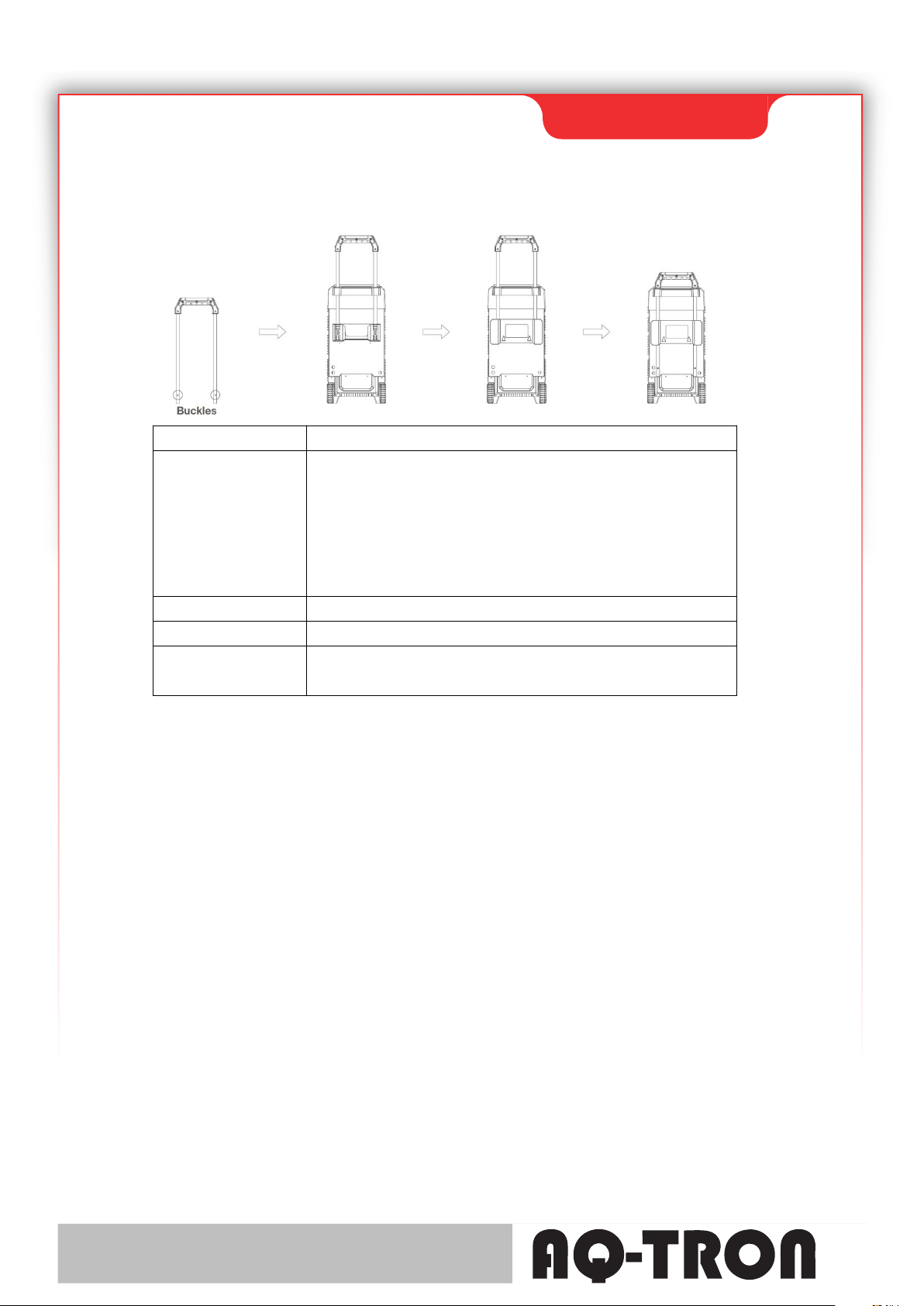
6) How to install the handle? Please follow the instructions. When you take the charger out
from the package, the handle is uninstalled. To install the handle, first pull the clamp
storage panel upwards and remove it, then a tool (e.g. screwdriver) is needed to help
make springback for the buckle until the buckles are in the right position (showed in
following second image). Remember to put on the clamp storage panel. If you want to
store the charger, just keep the handle pulled upwards in the right position. If you insist
to pull the handle down, first pull the clamp storage panel upwards and remove it, then
use the tool to make springback for the buckle and pull the handle down (remember to
put on the clamp storage panel at last).

USER GUIDE
BAT/45686
3
AC Input AC 230V 50/60Hz, 5.0kW Max
DC Output
Charge: DC 12V, 10A/20A/35A/50A or DC 24V,
10A/20A/35A/50A
Engine Start: DC 12V, 250A INTERMITTENT 5 SECONDS ON,
240 SECONDS OFF
or DC 24V, 250A INTERMITTENT 5 SECONDS ON, 240
SECONDS OFF.
Charge Type 10 Steps, Full-automatic Charging Cycle
Accessories Included Cable Clamps
Other Feature(s) Independent STD/GEL/AGM Battery Type Selection,
Dedicated Repair Mode, Alternator Check Function
O P E R A T I N G I N ST R U C T I O N S
Before charging, make sure the capacity of the battery to be charged is not lower than
Cmin (20Ah). On the rear of the charger you will find separate connector for 12V and 24V,
and connect the cable to the correct one.
CONNECTING TO THE BATTERY
1) Identify polarity of battery posts. The positive battery terminal is typically marked by
these letters or symbol (POS,P,+). The negative battery terminal is typically marked by
these letters or symbol (NEG,N,-).
2) Do not make any connections to the carburetor, fuel lines, or thin metal parts.
3) Identify if you have a negative or positive grounded vehicle. This can be done by done
by identifying which battery post (NEG or POS) is connected to the chassis.
4) For a negative grounded vehicle (most common): connect the RED POSITIVE clamp
first to the positive battery terminal, then connect the BLACK NEGATIVE clamp to the
negative battery terminal or vehicle chassis.

USER GUIDE
BAT/45686
4
5) For a positive grounded vehicle (very uncommon): connect the BLACK NEGATIVE
clamp first to the negative battery terminal, then connect the RED POSITIVE clamp to
the positive battery terminal or vehicle chassis.
6) When disconnecting, disconnect in the reverse sequence, removing the negative first (or
positive first for positive ground systems).
7) A marine (boat) battery must be removed and charged on shore. To charge it on board
requires equipment specially designed for marine use.
DISPLAY BUTTON
Press DISPLAY button until following LED is lit.
Voltage – When the charger is NOT charging a battery, the display will show the battery
VOLTAGE.
Battery % – When in charging, the digital display shows an estimated charge percentage
of the battery connected to the charger’s battery clamps.
Alternator % – The digital display shows an estimated output percentage of the vehicle’s
charging system connected to the charger’s battery clamps, compared to a properly
functioning system.
CHARGE
Press BATTERY TYPE button to choose first, then press RATE SELECTION button to
choose the charging
current. After that, press FUNCTION button until the CHARGE LED is lit to enter this
mode (digital display
shows CHARGE-ON). When in charging, pressing BATTERY TYPE button does NOT
work. To stop charging,
press FUNCTION button again and CHARGE LED will be off (digital display shows
CHARGE-OFF).

USER GUIDE
BAT/45686
5
Following is the detailed explanation for charging steps.
STEP 1: ANALYSING 1 (Checks if battery has connected with the charger)
STEP 2: DESULPHATION (Pulsing charging to remove sulphate)
STEP 3: SOFT START (Charges with gradually increasing charging current)
STEP 4: CONTROLLED CURRENT CHARGE (Adjusts the charging current
intelligently)
STEP 5: ANALYSING 2 (Tests if the battery can absorb charge)
STEP 6: CONSTANT OUTPUT CHARGE (Charges with constant voltage and
compensates fake full charge caused by high current charging)
STEP 7: RECOVERY CYCLE CHARGE (Absorbs more charge and compensates side
effect of reduced charging current)
STEP 8: ABSORPTION (Charges with constant trickle current for maximum battery
voltage)
STEP 9: ANALYSING 3 (Tests if the battery can hold charge)
STEP 10: MAINTENANCE (Continuously monitors the battery, and charges with trickle
current once the voltage is lower than threshold)
START
Your battery charger can be used to jump start your car if the battery is low. Follow all
safety instructions and precautions for charging your battery. Wear complete eye protection
and protective clothing. The procedures are as follows.

USER GUIDE
BAT/45686
6
WARNING: Using the ENGINE START feature WITHOUT a battery installed in the
vehicle will damage the vehicle’s electrical system.
1. Connect the charger to the battery following the instructions given in the
CONNECTING TO THE BATTERY section.
2. With the charger plugged in and connected to the battery and chassis, press FUNCTION
button until the START LED is lit.
3. Crank the engine until it starts or 3 seconds pass. If the engine does not start, wait 4
minutes before cranking again. This allows the charger and battery to cool down.
4. If the engine fails to start, use the CHARGE maximum rate (50A) to charge for some
minutes before attempting to crank the engine again.
5. After the engine starts, unplug the AC power cord before disconnecting the battery
clamps from the vehicle.
NOTE: If the engine does turn over but never starts, there is not a problem with the
starting system; there is a problem somewhere else with the vehicle. STOP cranking the
engine until the other problem has been diagnosed and corrected.
During the starting sequence listed above, the charger is set to one of three states:
Wait for cranking – While waiting for cranking, the digital display shows
START-READY. The charger waits until the engine is actually being cranked before
delivering the amps for engine start.
Cranking – When cranking is detected, the charger will automatically deliver up to its
maximum output as required by the starting system for up to 5 seconds.
Cool Down – After cranking, the charger enters a mandatory 240 seconds cool down state
(Pressing any button does NOT work). The digital display indicates the remaining cool
down time in seconds. It starts at 240 and counts down to 0. After 4 minutes, the digital
display will change from displaying the countdown to displaying START-READY.

USER GUIDE
BAT/45686
7
REPAIR
Press FUNCTION button until the REPAIR LED is lit to enter this mode (digital display
shows REPAIR-ON). It is an advanced battery recovery mode for repairing old, idle,
stratified or sulfated batteries. NOT all batteries can be recovered. For optimal results, take
the battery through a full charge cycle, bringing the battery to full charge, before using this
mode. This mode uses a high charging voltage and may cause some water loss in WET cell
batteries. Plus, some batteries and electronics may be sensitive to high charging voltages.
To minimize risks, disconnect the battery from the vehicle before using this mode.
To stop repairing, press FUNCTION button again and REPAIR LED will be off (digital
display shows REPAIROFF).
ALTERNATOR CHECK
Before the charger is connected with the battery which is well settled in the vehicle and
Alternator % LED is lit (press DISPLAY button), start the vehicle and turn on the vehicle’s
headlights. The alternator percent range is from 0% to 100%. Readings below 0% will read
LO and readings above 100% will read HI. If you get a HI or LO reading, have the
electrical system checked by a qualified technician.
E R R O R M E SSA G E S
1) E01 Display + ERROR LED lit: reverse connection
2) E02 Display + ERROR LED lit: temperature in charger is too high
3) E03 Display + ERROR LED lit: the battery cannot store electric charge (dead battery)
4) E04 Display + ERROR LED lit: no battery connected / battery voltage is lower than 1
volt (dead battery)
5) REPAIR-ON Display + REPAIR LED flashing: charger automatically enters repairing
mode
6) REPAIR-ON Display + REPAIR LED solid lit: manually choose repairing mode
Table of contents
Other AQ-Tron Batteries Charger manuals

AQ-Tron
AQ-Tron AQ1000 User manual

AQ-Tron
AQ-Tron BAT/48313 User manual

AQ-Tron
AQ-Tron AQHF12-15 Instruction Manual

AQ-Tron
AQ-Tron LAD/AQ2000 User manual

AQ-Tron
AQ-Tron LAD/AQ7000 User manual

AQ-Tron
AQ-Tron LAD/AQ3500 User manual

AQ-Tron
AQ-Tron BAT/45684 User manual

AQ-Tron
AQ-Tron BAT/49493 User manual

AQ-Tron
AQ-Tron AQ5000 User manual

AQ-Tron
AQ-Tron AQ15000 User manual