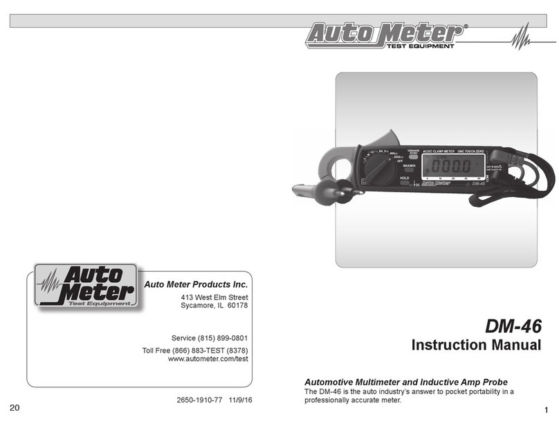
AutoMeter DM-40 User manual

DM-40
Operator’s Manual
Automotive Multimeter and Inductive Amp Probe
The DM-40 is the auto industry’s answer to pocket portability in a profes-
sionally accurate meter.
16
Test Equipment
Auto Meter Products Inc.

LIMITED WARRANTY
TABLE OF CONTENTS
SERVICE
For service send your product to Auto Meter in a well-packed shipping
carton. Please include a note explaining what the problem is along with
your phone number. If you are sending the product back for Warranty
adjustment, you must include a copy (or original) of your sales receipt
from the place of purchase.
12 MONTHS FROM DATE OF PURCHASE-CABLES 90 DAYS
The manufacturer warrants to the consumer that this product will be
free from defects in material or workmanship for a period of twelve
(12) months from the date of original purchase.
Products that fail within this 12 month warranty period will be repaired
or replaced at the manufacturer’s option to the consumer, when
determined by the manufacturer that the product failed due to defects
in material or workmanship. This warranty is limited to the repair or
replacement of parts and the necessary labor by the manufacturer to
effect the repair or replacement of the product. In no event shall the
manufacturer be responsible for special, incidental or consequential
damages or costs incurred due to the failure of this product.
Improper use, accident, water damage, abuse, unauthorized repairs
or alterations voids this warranty. The manufacturer disclaims any
liability or consequential damages due to breach of any written or
implied warranty on its test equipment.
WARRANTY AND SERVICE INFORMATION
Warranty claims to the manufacturer’s service department must be
transportation prepaid and accompanied with dated proof of purchase.
This warranty applies only to the original purchaser and is non-
transferable. Shipper damage incurred during return shipments is not
covered under this warranty. It is the responsibility of the shipper (the
customer returning the Test Equipment) to package the tester properly
to prevent any damage during return shipment. Repair costs for such
damages will be charged back to shipper (customer returning the Test
Equipment). Protect the product By shipping in original carton or add
plenty of over-pack cushioning such as crumpled up newspaper.
Battery Replacement --------------------------------------2
Safety ----------------------------------------------------------3
Maintenance and Cleaning-------------------------------3
Features-------------------------------------------------------4
Controls and Functions--------------------------------- 4-5
Operation Instructions
DC/AC Current Measurements ---------------------6
DC/AC Voltage Measurements ---------------------7
Frequency (Hz) Measurement ---------------------8
Continuity Test ------------------------------------------8
Resistance Measurement----------------------------8
Relative “ZERO” Measurements -------------------9
Holding the LCD Reading----------------------------9
Finding the MAX/MIN Value -------------------------9
Charging System Tests
State of Charge--------------------------------------- 10
Amp Draw Check------------------------------------- 10
Alternator Test----------------------------------------- 11
Starter Draw Test------------------------------------- 12
Specications ---------------------------------------------- 13
Warranty ---------------------------------------------------- 15
Contact Information -------------------------------------- 16
BATTERY REPLACEMENT
When the low battery symbol is displayed on the LCD or the LCD is dark,
replace the old batteries with two (AA) batteries.
1. Turn the power off and remove the test
leads from the clamp meter.
2. Remove the screw of the battery cover.
3. Lift and remove the battery cover.
4. Remove the old batteries.
5. lnsert two (AA) batteries.
6. Replace the battery cover and
secure the screw.
2
15
Battery Replacement --------------------------------------2
Safety ----------------------------------------------------------3
Maintenance and Cleaning-------------------------------3
Features-------------------------------------------------------4
Controls and Functions------------------------------- 4 - 5
Operation Instructions
DC/AC Current Measurements ---------------------6
DC/AC Voltage Measurements ---------------------7
Frequency (Hz) Measurement ---------------------8
Continuity Test ------------------------------------------8
Resistance Measurement----------------------------8
Relative “ZERO” Measurements -------------------9
Holding the LCD Reading----------------------------9
Finding the MAX/MIN Value -------------------------9
Charging System Tests
State of Charge--------------------------------------- 10
Amp Draw Check------------------------------------- 10
Alternator Test----------------------------------------- 11
Starter Draw Test------------------------------------- 12
Specications ---------------------------------------- 13 - 14
Warranty ---------------------------------------------------- 15
Contact Information -------------------------------------- 16

B
SAFETY
Carefully read all operating instructions before using the DM-40
Wear eye protection when working around batteries.
Keep sparks, ames, or cigarettes away from batteries.
Keep hair, hands, and clothing as well as tester leads and cords
away from moving blades and belts.
Provide adequate ventilation to remove car exhaust.
WARNING: If the clamp meter is used in a manner not specied
by the manufacturer, the protection provided by the clamp meter
may be impaired.
EN 61010-2-032
CAT II 600V
CAT III 300V
Pollution Degree2
SPECIFICATIONS CONTINUED
Denition of Symbols
on the DM-40 and in
the manual.
Caution: Refer to
Accompanying
Documents
Caution: Risk of
Electric Shock
Double Insulation
Overvoltage Category I (CAT I):
Equipment for connection to circuits in which
measures are taken to limit the transient
overvoltages to an appropriate low lever.
Overvoltage Category II (CAT II):
Energy-consuming equipment to be supplied from
the xed installation.
Overvoltage Category III (CAT III):
Equipment in xed installations.
Indoor Use
Conductor Size: 23mm max. (approx.)
Battery Type: Two 1.5V AA
Display: 3 3/4 LCD with 40 seg. bar graph
Overload Indication: Left most digit blanks
Power Consumption: 10mA (approx.)
Low battery Indication
Sampling Time: 2 times/sec. (display)
20 times/sec. (bar graph)
Operating Temperature: -10oC to 50oC
Operating Humidity: Less than 85% relative
Storage Temperature -20oC to 60oC
Storage Humidity Less than 75% relative
Dimension: 7.2” x 2.5” x 1.4”
Weight: 190g (batteries included)
Accessories: Carrying bag
Users manual
2-1.5V AA batteries
MAINTENANCE and CLEANING
Periodically wipe the case with a damp cloth and detergent; do not
use abrasives or solvents.
Use the hand strap to avoid accidental dropping. Negligent use of
your meter will void the warranty.
Keep away from heat and liquid solvents.
Keep in a protective place when not in use.
14
3

B
DC Current:
Range Resolution Accuracy Overload Protection
40A 10mA
+
1.0% 2dgts DC 400A
0-150A 100mA 1.0% 2dgts DC 400A
150-200A 100mA 2.2% 2dgts DC 400A
AC Current:
Accuracy
Range Resolution 50/60 Hz 40-1KHz
Overload
Protection
40A 10mA 1.0% 3dgts 1.5% 4dgts AC 400A
0-150A 100mA 1.0% 3dgts 1.5% 4dgts AC 400A
150-200A 100mA 2.2% 3dgts 2.5% 4dgts AC 400A
DC Voltage: (Input Impedance: 10MΩ)
Range Resolution Accuracy Overload Protection
400V 0.1V 1.0% 2dgts �
AC Voltage: (Input Impedance 10M
Ω)
Accuracy
Range Resolution 50/60 Hz 40-1KHz
Overload
Protection
400V 0.1V AC 800V
_
+
_
+
_
+
_
+
_
+
_
+
_
+
_
+
_
+
_+
_
+
_
+
_
+
_
+
_
+
_
+
_
+
_
+
_
+
_
DC 1000V
1.5% 2dgts
__2.0% 5dgts
__
++
RESISTANCE (Ω): (open voltage 0.4)
Range Resolution Accuracy Overload Protection
40-400Ω0.1 Ω+1.0%+2dgts AC 600V
CONTINUITY: (open voltage 0.4v, Overload Protection AC 600V)
Range Resolution Accuracy Beeping
40-400Ω0.1Ω+1.0%+2dgts <40.0Ω
(approx.)
_ _
CONTINUITY:
Range Resolution Accuracy Beeping
40-400Ω0.1Ω+1.0%+2dgts <40.0Ω
(approx.)
_ _
FREQUENCY: (Auto Range)
Range Resolution Accuracy OL Protection
100-1000K 0.01-100 +1.0%+2dgts AC 600V
_ _
Sensitivity
2V
+ +
FEATURES
Accurate AC/DC digital clamp meter for current measurement.
High resolution readout (10mA to 40A DC/AC range).
One touch zero for DC Amps adjustment.
23 mm diameter jaw. Ideal for working under dash or in cable
bundles.
Fast bar graph display (20 times/sec.) for transient observation.
Continuity and frequency measurements.
Max/Min and Data Hold functions.
600V overload protection for ohm measurement.
ON/Off switch to conserve battery life.
CONTROLS AND FUNCTIONS
1. Transformer Jaw is used to pick up DC/AC current signal. The jaw
must enclose a single conducting wire.
2. Transformer Trigger is used to open the jaw.
3. Function Selector Switch is used to select the function such as
DCA, ACA, DCV, ACV, Hz, Ohm and Continuity.
4. On/Off Switch is used to turn the power on or off.
5. Data Hold Button holds the LCD reading when pushed. Press
again to release it.
SPECIFICATIONS (23oC+5oC)
4
13

650A
CONTROLS AND FUNCTIONS CONT.
6. Max/Min Hold Button is used to enable the maximum or minimum
value to be displayed and updated during measurement. Press once,
minimum value will be displayed and updated. Press again, maximum
value will be displayed and updated. Press the third time and the meter
will return to normal measurement mode. The Zero function will be
disabled if MAX/MIN is enabled.
7. Zero/Relative Button sets the current reading to zero and is
used as a zero reference value for all subsequent measurements. This
function is also used to remove offset values caused by the residual
magnetism remaining in the core after a DC current measurement.
The Zero/Relative function will be disabled if the MAX/MIN button is
pressed.
8. LCD is a 3 3/4 digit Liquid Crystal Display with a maximum indication
of 3999. The functions included are units, symbols, bar graph, sign,
decimal points, low battery symbols, MAX/MIN symbols, and zero
symbol.
9. Battery Symbol appears if the battery voltage drops below the
minimum required voltage. Refer to page 3 for battery replacement.
10. Zero/Relative Symbol means a reference value has been
subtracted from the actual reading. The reading shown is an offset
value. Press and hold the zero button for 2 seconds to disable this
function.
11. Data Hold Symbol appears on the LCD when the hold button is
pressed.
12. Bar graph has forty segments. It displays segments proportional to
the actual reading. Each segment represents one count.
13. MAX or MIN is displayed on the LCD when the MAX/MIN button is
pressed.
14. Continuity Symbol appears on the LCD if the ohm and continuity
function is selected.
15. Units are displayed on the LCD when a function is selected. The
corresponding symbols are: V, A, W, and Hz.
16. VWHz Input Terminal (Red) is used as input for voltage, ohm/
continuity or frequency measurements.
17. COM Terminal (Black) is used as a common reference input.
18. Hand Strap allows you to put your hand through to avoid accidental
drop of the clamp meter.
STARTER DRAW TEST
STARTER
SETUP
1. Check with manufacture's proper procedure to disable ignition if
needed. Improper methods could cause damage to vehicles that
are computer controlled.
2. Determine the manufactures Starter Draw specications. If not
available use the following chart as a guide.
3. Select DC 200 Amp and zero the DM-40 by pressing the yellow
button.
4. Press the MAX/MIN button twice and make sure the display
reads HOLD MAX.
5. Clamp the DM-40 around the positive conductor leading to the
starter (See illustration above). Make sure the small arrow inside
the clamp is pointing in the direction of the current towards the
starter. Also make sure the DM-40 is clear of any moving belts,
fan blades or anything that might damage the meter.
6. Start or crank the engine for 3 to 5 seconds.
7. Read the DM-40 and compare with manufactures specications.
8. High Amp reading indicates a faulty starter or engine timing
that would put an extra load upon the starter. Possible starter
problems are shorted windings, bent armature, broken housing or
bad bearings.
12
5

Note: Direction of
current arrow inside
clamp opening
+
DC/AC CURRENT MEASUREMENTS
WARNING: Make sure that all the test leads are disconnected from
the meter’s terminals for current measurement.
DC CURRENT
1. Set the rotary switch at 40A or 200A
2. Push the zero button to zero Amp reading.
3. Press the trigger to open the jaw and fully enclose the
conducting wire to be measured. Be sure there is no air gap
between the two half jaws.
4. Read the measured value from the LCD.
AC CURRENT
1. Set the rotary switch at 40A~or 200A~.
2. Press the trigger to open the jaw and fully enclose the
conducting wire to be measured. Be sure there is no air gap
between the two half jaws.
3. Read the measured value from the LCD.
ALTERNATOR TEST
ALTERNATOR
SETUP
1. Select DC Volts on the DM-40.
2. Start the engine.
3. Place the Volt leads to the red (+) positive and black (-) battery
terminals.
4. Allow voltage to stabilize. The reading should be from 13.2
to 15.0 Volts DC. If the reading is high the alternator is over
charging and could damage the battery.
5. Turn on all accessories including the headlights.
6. The reading should be from 12.8 to 15.0 Volts DC. If the reading
is low the alternator is not charging.
7. Switch the DM-40 to DC 200 Amps.
8. Clamp the DM-40 around the positive alternator conductor
leading to the positive terminal of the battery (See illustration to
the right).
9. Make sure the small arrow inside the clamp is pointing in the
direction of the current towards the battery. Also make sure the
DM-40 is clear of any moving belts, fan blades or anything that
might damage the meter.
10. If output is lower in DC Amps than the accessories would draw
then the alternator may not be charging. Repeat step 6 to see if
the voltage has droped.
11. Select the AC 40 Amp on the DM-40.
12. Clamp the DM-40 as explained in step 11.
13. With the engine still running and all accessories on, the current
ripple should be less than 10 Amps AC AC. If more, the diodes
are bad.
6
11

DC/AC VOLTAGE MEASUREMENTS
WARNING: Maximum input for DC Volts is 1000, and for AC Volts
is 750. Do not attempt to take any voltage measurement that
exceeds the limits. Exceeding the limits could cause electrical
shock and damage to the meter.
DC VOLTAGE
1. Set the rotary switch at V .
2. Insert the test leads into the input jack.
3. Connect the test prods of the test leads in PARALLEL to the
circuit to be measured.
4. Read the measured value from the LCD display.
AC VOLTAGE
1. Set the rotary switch at ~V.
2. Insert the test leads into the input jack.
3. Connect the test prods of the test leads in PARALLEL to the
circuit to be measured.
4. Read the measured value from the LCD display.
CHARGING SYSTEM TESTS
The following section shows what you can do
with the DM-40 in testing your charging system
State of Charge
1. Select DC Volts on the DM-40.
2. Place the Volt leads to the red (+) positive and black (-) battery
terminals.
3. If the Volts are less than 12.5 Volts the battery needs charging.
Amp Draw Check
4. Turn off ignition and all accessories.
5. Select DC 40 Amps on the DM-40.
6. Zero the DM-40 by pressing the yellow button.
7. Clamp the DM-40 around the positive (+) battery cable . Make
sure it is clamped around all wires.
8. If the display is above 2 Amps there is probably a draw upon
the battery by the electrical system. This will drain the battery.
Isolate and follow a suspected circuit and repeat reading until
the problem is found. Consider a negligible drain with an on
board computer.
10
7

RESISTANCE MEASUREMENT
1. Set the rotary switch to Ω.
2. Insert the test leads into the input jack.
3. Connect the test probes of the test leads to the two ends
of the resistor or circuit to be measured.
4. Read the measured value from the LCD.
CONTINUITY TEST
WARNING: Before taking any in-circuit resistance
measurement, remove power from the circuit being tested and
discharge all the capacitors.
1. Turn the rotary switch to Ωposition.
2. lnsert the test leads into the input jack.
3. Connect the test probes of the test leads to the two ends
of the resistor or circuit to be measured.
4. Read the measured value from the LCD.
5. lf the resistance is lower than 40 Ω, a beeping sound will
be heard.
FREQUENCY AND CONTINUITY TESTS RELATIVE READING MEASUREMENTS
ZERO
The “ZERO” button also can be used to make a relative measurement.
Once the button is pushed, the current reading is set to zero and a zero
symbol will be displayed on LCD. All the subsequent measurement shall
be displayed as a relative value with respect to the value being zeroed.
This function can be used to remove offset values caused by the residual
magnetism remaining in the core from DC current measurements. Press
the zero button for 2 seconds to return to normal mode. This function
is disabled if MAX/MIN function is enabled. Please watch for symbol
displayed on LCD.
HOLDING THE LCD READING
Press the HOLD button and the reading will be held on the LCD.
Press again to release.
FINDING THE MAX/MIN VALUE
Press the MAX/MIN button to enable the maximum and minimum values
to be recorded and updated during measurement. Push the button once,
the maximum value will be displayed and updated. Push again (second
push), the minimum value will be displayed. Push again (third push), the
MAX/MIN function will be disabled by returning to normal measurement
mode. If MAX/MIN button is pressed, the ZERO function will be disabled
and the ZERO symbol will disappear from LCD.
FREQUENCY (Hz) MEASUREMENT
1. Set the rotary switch to Hz.
2. Insert the test leads into the input jacks.
3. Connect the test probes in PARALLEL to the signal or circuit
to be measured.
4. Read the measured value on the LCD.
8
9
Table of contents
Other AutoMeter Multimeter manuals
