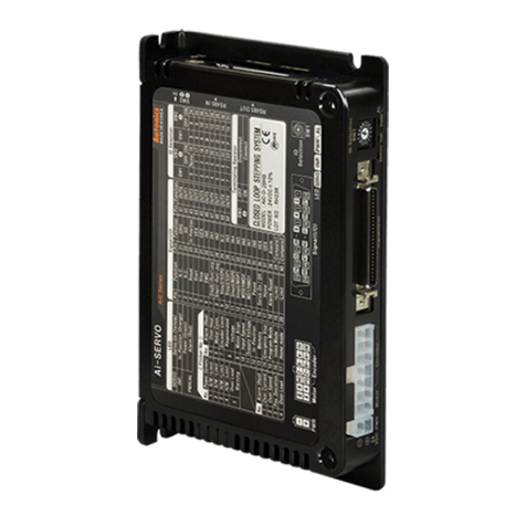
Autonics AiC Series User manual

AiC Series
User Manual
AiC Series
Controller Integrated 2-Phase Closed-Loop
Stepper Motor System

ii © Copyright Reserved Autonics Co., Ltd.

Preface
© Copyright Reserved Autonics Co., Ltd. iii
Preface
Thank you for purchasing Autonics product.
Please familiarize yourself with the information contained in the Safety Precautions section
before using this product.
This user manual contains information about the product and its proper use, and should be kept
in a place where it will be easy to access.

User Manual Guide
iv © Copyright Reserved Autonics Co., Ltd.
User Manual Guide
Please familiarize yourself with the information in this manual before using the product.
This manual provides detailed information on the product's features. It does not offer any
guarantee concerning matters beyond the scope of this manual.
This manual may not be edited or reproduced in either part or whole without permission.
A user manual is not provided as part of the product package. Visit our web site
(www.autonics.com) to download a copy.
The manual's content may vary depending on changes to the product's software and other
unforeseen developments within Autonics, and is subject to change without prior notice.
Upgrade notice is provided through out homepage.
We contrived to describe this manual more easily and correctly. However, if there are any
corrections or questions, please notify us these on our homepage.

User Manual Symbols
© Copyright Reserved Autonics Co., Ltd. v
User Manual Symbols
Symbol
Description
Supplementary information for a particular feature.
Failure to follow instructions can result in serious injury or death.
Failure to follow instructions can lead to a minor injury or product damage.
An example of the concerned feature's use.
※1
Annotation mark.

Safety Considerations
vi © Copyright Reserved Autonics Co., Ltd.
Safety Considerations
Following these safety precautions will ensure the safe and proper use of the product and
help prevent accidents, as well as minimizing possible hazards.
Safety precautions are categorized as Warnings and Cautions, as defined below:
Warning
Failure to follow these instructions may result in serious
injury or death.
Caution
Failure to follow these instructions may result in personal
injury or product damage.
Fail-safe device must be installed when using the unit with machinery that may cause
serious injury or substantial economic loss. (e.g. nuclear power control, medical equipment,
ships, vehicles, railways, aircraft, combustion apparatus, safety equipment, crime/disaster
prevention devices, etc.)
Failure to follow this instruction may result in fire, personal injury, or economic loss.
Do not connect, repair, or inspect the unit while connected to a power source.
Failure to follow this instruction may result in fire.
Install the unit after considering counter plan against power failure.
Failure to follow this instruction may result in personal injury, or economic loss.
Check 'Connections' before wiring.
Failure to follow this instruction may result in fi re.
Do not disassemble or modify the unit.
Failure to follow this instruction may result in fire.
Install the driver in the grounded housing or ground it directly.
Failure to follow this instruction may result in electronic shock, personal injury.
Do not touch the unit during or after operation for a while.
Failure to follow this instruction may result in burn due to high temperature of the surface.
Emergency stop directly when error occurs.
Failure to follow this instruction may result in fi re, or personal injury.
When connecting the power input, use AWG 18(0.75mm2) cable or over.
Install over-current prevention device (e.g. the current breaker, etc) to connect the driver
with power.
Failure to follow this instruction may result in fire.
Check the control input signal before supplying power to the driver.
Failure to follow this instruction may result in personal injury or product damage by
unexpected signal.
Install a safety device to maintain the vertical position after turn off the power of this driver.
Failure to follow this instruction may result in personal injury or product damage by
releasing holding torque of the motor.
Use the unit within the rated specifi cations.
Failure to follow this instruction may result in fire or product damage.

Safety Considerations
© Copyright Reserved Autonics Co., Ltd. vii
Use dry cloth to clean the unit, and do not use water or organic solvent.
Failure to follow this instruction may result in fire.
Do not use the unit in the place where fl ammable/explosive/corrosive gas, humidity, direct
sunlight, radiant heat, vibration, impact, or salinity may be present.
Failure to follow this instruction may result in fi re or explosion.
The driver may overheat depending on the environment.
Install the unit in the well ventilated place and forced cooling with a cooling fan.
Failure to follow this instruction may result in product damage and degradation.
Keep metal chip, dust, and wire residue from fl owing into the unit.
Failure to follow this instruction may result in fi re or product damage.
Use the designated motor only.
Failure to follow this instruction may result in fi re or product damage.
The above specifications are subject to change and somd models may be discontinued
without notice.
Be sure to follow cautions written in the instruction manual, user manual and the
technical descriptions (catalog, homepage).

Cautions during Use
viii © Copyright Reserved Autonics Co., Ltd.
Cautions during Use
Follow instructions in 'Cautions during Use'.
Otherwise, it may cause unexpected accidents.
24VDC power supply should be insulated and limited voltage/current or Class 2, SELV
power supply device.
Re-supply power after min. 1 sec from disconnected power.
In case communication is unstable due to the noise generated by supplied power or
peripheral device, use ferrite core at communication line.
It is recommended to use 485 converter with the separate power.
(Autonics product, SCM-38I, recommended)
The thickness of cable should be same or thicker than the below specifications when
connecting the cable for the connector.
①CN1 (power connector): AWG18
②CN2 (motor+encoder connector): AWG22, AWG24
③CN3 (I/O connector): AWG28
Keep the distance between power cable and signal cable more than 10cm.
Motor vibration and noise can occur in specifi c frequency period
①Change motor installation method or attach the damper.
②Use the unit out of the dedicated frequency range when vibration and noise occurs due to
changing motor RUN speed.
For using motor, it is recommended to maintenance and inspection regularly.
①Unwinding bolts and connection parts for the unit installation and load connection
②Strange sound from ball bearing of the unit
③Damage and stress of lead cable of the unit
④Connection error with motor
⑤Inconsistency between the axis of motor output and the center, concentric (eccentric,
declination) of the load, etc.
This product does not prepare protection function for a motor.
This unit may be used in the following environments.
①Indoors (in the environment condition rated in 'Specifi cations')
②Altitude max. 2,000m
③Pollution degree 2
④Installation category II

Table of Contents
© Copyright Reserved Autonics Co., Ltd. ix
Table of Contents
Preface.............................................................................................................................iii
User Manual Guide ......................................................................................................... iv
User Manual Symbols......................................................................................................v
Safety Considerations..................................................................................................... vi
Cautions during Use.......................................................................................................viii
Table of Contents ............................................................................................................ ix
1Product Overview .....................................................................................13
1.1 Features.............................................................................................................13
1.2 Components and Accessories...........................................................................14
1.2.1 Driver..........................................................................................................14
1.2.2 Motor..........................................................................................................14
1.2.3 Sold Separately..........................................................................................14
1.3 Ordering Information..........................................................................................15
1.3.1 Driver..........................................................................................................15
1.3.2 Motor..........................................................................................................15
1.4 Models ...............................................................................................................16
2Specifications............................................................................................17
2.1 Driver..................................................................................................................17
2.2 Motor..................................................................................................................19
2.2.1 Frame Size 42mm......................................................................................19
2.2.2 Frame Size 56mm......................................................................................19
2.2.3 Frame Size 60mm......................................................................................19
2.2.4 Common Specifications .............................................................................20
2.2.5 Encoder......................................................................................................21
3Dimensions................................................................................................23
3.1 Driver..................................................................................................................23
3.2 Motor..................................................................................................................24
3.2.1 Frame Size 42mm......................................................................................24
3.2.2 Frame Size 56mm......................................................................................24
3.2.3 Frame Size 60mm......................................................................................24
4Installation of Motor..................................................................................27
4.1 Mounting Direction of Motor ..............................................................................27
4.2 Mounting of Motor..............................................................................................28
4.2.1 Frame Size 42mm......................................................................................28
4.2.2 Frame Size 56mm / Frame Size 60mm .....................................................28
4.3 Connection with Load........................................................................................29
4.3.1 Direct Load Connection with Coupling.......................................................29
4.3.2 Load Connection with Pulley, Belt, and Wire .............................................29
4.3.3 Load Connection with Gear........................................................................29
4.4 Installation Conditions........................................................................................30

Table of Contents
x © Copyright Reserved Autonics Co., Ltd.
5Connection ................................................................................................31
6Characteristics ..........................................................................................33
6.1 Frame Size 42mm .............................................................................................33
6.2 Frame Size 56mm .............................................................................................33
6.3 Frame Size 60mm .............................................................................................33
7Driver Unit Descriptions...........................................................................35
7.1 Connectors.........................................................................................................35
7.1.1 CN1: Power Connector ..............................................................................35
7.1.2 CN2: Motor+Encoder Connector................................................................35
7.1.3 CN3: I/O Connector....................................................................................36
7.1.4 CN4: RS485 Communication Cable Connector.........................................38
7.2 Connector Specifications...................................................................................38
7.3 Switches.............................................................................................................39
7.3.1 SW1: ID Setting Switch..............................................................................39
7.3.2 SW2: ID Setting/Terminating Resistance DIP Switch.................................39
7.4 Driver Status Indicator.......................................................................................40
7.5 Sold separately..................................................................................................41
7.5.1 I/O Cable (CJ-MP50-HP□, standard: AiC TAG)........................................41
7.5.2 Power Cable (CJ-PW-□)...........................................................................42
7.5.3 Motor+Encoder Cable (normal: C1D14M-□/moving: C1DF14M-□).........42
8Control Input/Output.................................................................................43
8.1 Input...................................................................................................................43
8.1.1 Exclusive Input (20)....................................................................................43
8.1.2 General Input (9) ........................................................................................48
8.1.3 Example of Input Circuit Connection..........................................................48
8.2 Output................................................................................................................49
8.2.1 Exclusive Output (4)...................................................................................49
8.2.2 General Output (10) ...................................................................................53
8.2.3 Example of Output Circuit Connection.......................................................53
9Drive...........................................................................................................55
9.1 Index Mode........................................................................................................56
9.2 Jog Mode...........................................................................................................57
9.3 Continuous Mode...............................................................................................58
9.4 Program Mode...................................................................................................59
9.5 Home Search.....................................................................................................60
10 Program Instructions................................................................................61
10.1 Drive Instruction.................................................................................................62
10.1.1 ABS (absolute position move)....................................................................62
10.1.2 INC (relative position move).......................................................................64
10.1.3 HOM (home search)...................................................................................65
10.2 Input/Output Instruction.....................................................................................66
10.2.1 ICJ (input condition jump)...........................................................................66
10.2.2 IRD (input wait)...........................................................................................66
10.2.3 OPC (output port ON/OFF) ........................................................................66
Table of Contents
© Copyright Reserved Autonics Co., Ltd. xi
10.2.4 OPT (output port ON pulse) .......................................................................67
10.2.5 CMP (compare output)...............................................................................67
10.3 Program control Instruction ...............................................................................68
10.3.1 JMP (jump).................................................................................................68
10.3.2 REP (repeat start) ......................................................................................68
10.3.3 RPE (repeat end) .......................................................................................69
10.3.4 END (program end)....................................................................................69
10.3.5 POS (position set)......................................................................................69
10.4 Others................................................................................................................69
10.4.1 TIM (ready).................................................................................................69
11 Driver Function .........................................................................................71
11.1 General Drive.....................................................................................................71
11.1.1 Fixed Pulse and Continuous Pulse Drive...................................................71
11.1.2 Speed curve...............................................................................................73
11.2 Home Search.....................................................................................................78
11.2.1 General Home Search (home search method=0)......................................78
11.2.2 Limit Home Search (home search method=1)...........................................79
11.2.3 Zero Home Search (home search method=2) ...........................................80
11.2.4 Torque Home Search (home search method=3)........................................81
11.3 Other functions...................................................................................................82
11.3.1 Limit operation............................................................................................82
11.3.2 Stop current................................................................................................82
11.3.3 Stop Current Fix.........................................................................................82
11.3.4 Speed Filter................................................................................................83
11.3.5 Position Control Gain Setting.....................................................................84
11.3.6 In-Position ..................................................................................................85
12 Troubleshooting........................................................................................87

Table of Contents
xii © Copyright Reserved Autonics Co., Ltd.

1 Product Overview
© Copyright Reserved Autonics Co., Ltd. 13
1Product Overview
1.1 Features
AiC Series is 2-phase closed-loop stepper motor driver built-in motino controller function.
This unit is stand alone type and it drives through I/O with/without PC. There are settings; PI-
Gain, Speed Filter, In-Position and 4 modes. It minimizes motor heat generation due to current
setting during home search drive, stop.
It controls up to 31-axis via RS485 communication.
Motor driver and controller integral type
Competitive price compared to the servo motor and closed-loop function and fast response
for short-distance continuous drive
Controllable maximum 31 axis with RS485 communication
4 type of operation mode: jog mode, continuous mode, index mode (64), program mode
(256)
Improved user convenience with providing 50 I/O pins
C language library provided (32-bit, 64-bit)
Dedicated Windows program (atMotion) provided
Responding rapidly and maintaining torque in stop without hunting
Easy to use without tuning (various gain settings via programming)
Applicable to the precision equipment such as optical inspection equipment with
the features of maintaining torque in stop and having no micro vibration (hunting)
Containing various resolutions (electric gear)
: 500, 1000, 1600, 2000, 3200, 3600, 5000, 6400, 7200, 10000 (10-level)
Various alarm functions
: 17 alarms; over current, over speed, over heat, motor connection error, encoder
connection error
Frame size 42mm, 56mm, 60mm supported

1 Product Overview
14 © Copyright Reserved Autonics Co., Ltd.
1.2 Components and Accessories
1.2.1 Driver
1.2.2 Motor
Make sure all of the above components are included with your product package before use. If a
component is missing or damaged, please contact Autonics or your distributor.
1.2.3 Sold Separately
(1) I/O cable, Model: CJ-MP50-HP□(standard: AiC TAG)
(2) Power cable, Model: CJ-PW-□
(3) Motion+Encoder cable, Model-Normal: CID14M-□/ Moving: CIDF14M-□

1 Product Overview
© Copyright Reserved Autonics Co., Ltd. 15
1.3 Ordering Information
1.3.1 Driver
Ai
C
-
D
-
60
L
A
Item
Description
①Series
Ai
Artificial intelligent
②Category
C
Controller
③Item
D
Driver
④Motor frame size
42
42×42mm
56
57.2×57.2mm
60
60×60mm
⑤Motor length
S
Short (42mm: 67.5mm, 56mm: 77.3mm, 60mm: 81.9mm)
M
Middle (42mm: 73.5mm, 56mm: 90.3mm, 60mm: 102.8mm)
L
Long (42mm: 81.5mm, 56mm: 111.3mm, 60mm: 119.8mm)
⑥Encoder resolution
A
10,000PPR (2,500PPRⅹ4-multiply)
1.3.2 Motor
Ai
-
M
-
60
L
A
Item
Description
①Series
Ai
Artificial intelligent
②Item
M
Motor
③Motor frame size
42
42×42mm
56
57.2×57.2mm
60
60×60mm
④Motor length
S
Short (42mm: 67.5mm, 56mm: 77.3mm, 60mm: 81.9mm)
M
Middle (42mm: 73.5mm, 56mm: 90.3mm, 60mm: 102.8mm)
L
Long (42mm: 81.5mm, 56mm: 111.3mm, 60mm: 119.8mm)
⑤Encoder resolution
A
10,000PPR (2,500PPRⅹ4-multiply)

1 Product Overview
16 © Copyright Reserved Autonics Co., Ltd.
1.4 Models
Set
Driver
Motor
AiC-42SA
AiC-D-42SA
Ai-M-42SA
AiC-42MA
AiC-D-42MA
Ai-M-42MA
AiC-42LA
AiC-D-42LA
Ai-M-42LA
AiC-56SA
AiC-D-56SA
Ai-M-56SA
AiC-56MA
AiC-D-56MA
Ai-M-56MA
AiC-56LA
AiC-D-56LA
Ai-M-56LA
AiC-60SA
AiC-D-60SA
Ai-M-60SA
AiC-60MA
AiC-D-60MA
Ai-M-60MA
AiC-60LA
AiC-D-60LA
Ai-M-60LA

2 Specifications
© Copyright Reserved Autonics Co., Ltd. 17
2Specifications
2.1 Driver
Model
AiC-D-
42SA
AiC-D-
42MA
AiC-D-
42LA
AiC-D-
56SA
AiC-D-
56MA
AiC-D-
56LA
AiC-D-
60SA
AiC-D-
60MA
AiC-D-
60LA
Power supply
24VDCᜡ
Allowable voltage
range
90 to 110% of the rated voltage
Power
consu
mption
STOP※1
Max. 10W
Max. 12W
Max. 15W
Max.
during
operation
※2
Max. 60W
Max. 120W
Max. 240W
Max. RUN current
※3
1.7A/Phase
3.5A/Phase
STOP current ※4
20 to 100% of max. RUN current (factory default: 50%)
Rotation speed
0 to 3000rpm
Resolution ※4
500 (factory default), 1000, 1600, 2000, 3200, 3600, 5000, 6400, 7200, 10000 PPR
Speed filter※4
Disable, 2, 4, 6, 8 (factory default), 10, 20, 40, 60, 80, 100, 120, 140, 160, 180, 200 ms
Positioning gain※4
(P Gain, I Gain)
= (1, 1), (2, 1), (3, 1), (4, 1), (5, 1), (1, 2), (2, 2), (3, 2), (4, 2), (5, 2), (1, 3), (2, 3), (3, 3),
(4, 3), (5, 3), user setting
Positioning range
-2,147,483,648 to +2,147,483,647
In-Position
Fast Response: 0 to 7 or Accurate Response: setting range among 0 to 7
Motor rotation
direction※4
CW, CCW
Status indicator
ㆍPower/Warning indicator: green LED ㆍAlarm indicator: red LED
ㆍIn-Position indicator: yellow LED ㆍServo On/Off indicator: orange LED
ㆍRS485 DATA IN/OUT indicator: green/yellow LED
I/O voltage level
[H]: 5-30VDCᜡ, [L]: 0-2VDC
I/O
Input
Exclusive input: 20, general input: 9
Output
Exclusive output: 4, general output: 10
External power
supply
VEX (recommended: 24VDCᜡ): 2, GEX (GND): 2
Operation mode
Jog / Continuous / Index / Program mode
Index step
numbers
64 steps
Progr
am
functi
on
Steps
256 steps
Control
command
ABS (move absolute position), INC (move incremental position), HOM (home search),
ICJ (jump input condition), IRD (waiting input), OPC (on/off of output port), OPT (on
pulse from output port), JMP (jump), REP (start repetition), RPE (end repetition),
END (end program), POS (position set), TIM (timer), CMP (compare output)

2 Specifications
18 © Copyright Reserved Autonics Co., Ltd.
Model
AiC-D-
42SA
AiC-D-
42MA
AiC-D-
42LA
AiC-D-
56SA
AiC-D-
56MA
AiC-D-
56LA
AiC-D-
60SA
AiC-D-
60MA
AiC-D-
60LA
Progr
am
functi
on
Start
Power ON program start function
Home
search
Power ON home search function
Home search
mode
Home, limit home, zero home, torque home
Communication
RS485
Speed※4: 9600, 19200, 38400, 57900, 115200 (factory default) [bps]
Multiaxial control
31-axis
ID setting switch
16-bit rotary switch (0 to F), 1-bit piano switch
Alarm output
Over current, over speed, position tracking, over load, over heat, motor connection,
encoder connection, regenerative voltage, motor misalignment, command speed, input
voltage, in-position, memory, emergency stop, program mode, index mode, home search
mode
Warning output
+software limit, +hardware limit, -software limit, -hardware limit, over load
Insulation
resistance
Over 100MΩ(at 500VDC megger)
Dielectric strength
1,000VAC 60Hz for 1 min
Vibration
1.5mm amplitude at frequency of 10 to 55Hz (for 1 min) in each X, Y, Z direction for 2
hours
Shock
300m/s2(approx. 30G) in each X, Y, Z direction for 3 times
Envir
onme
nt
Ambient
temp.
0 to 50°C, storage: -10 to 60°C
Ambient
humi.
35 to 85%RH, storage: 10 to 90%RH
Approval
ᜢ
Protection
structure
IP20 (IEC standard)
Weight※5
Approx. 460g (approx. 300g)
※1: Based on the ambient temperature 25℃, ambient humidity 55%RH, and STOP current 50%.
※2: Max. power consumption during operation. When changing the load rapidly, instantaneous peak current may
increase. The capacity of power supply should be over 1.5 to 2 times of max. power consumption.
※3: RUN current varies depending on the input RUN frequency and max. RUN current at the moment varies also.
※4: Settable with the dedicated program.
※5: The weight includes packaging. The weight in parenthesis is for unit only.
※Environment resistance is rated at no freezing or condensation.

2 Specifications
© Copyright Reserved Autonics Co., Ltd. 19
2.2 Motor
2.2.1 Frame Size 42mm
Model
Ai-M-42SA
Ai-M-42MA
Ai-M-42LA
Max. stop torque※1
2.55kgf.cm (0.25N.m)
4.08kgf.cm (0.4N.m)
4.89kgf.cm (0.48N.m)
Rotor moment of
inertia
35g.cm2
(35ⅹ10-7kg.m2)
54g.cm2
(54ⅹ10-7kg.m2)
77g.cm2
(77ⅹ10-7kg.m2)
Rated current
1.7A/Phase
Resistance
1.7Ω/Phase ±10%
1.85Ω/Phase ±10%
2.1Ω/Phase ±10%
Inductance
1.9mH/Phase ±20%
3.5mH/Phase ±20%
4.4mH/Phase ±20%
Weight※2
Approx. 0.45kg
(approx. 0.34kg)
Approx. 0.52kg
(approx. 0.41kg)
Approx. 0.59kg
(approx. 0.48kg)
2.2.2 Frame Size 56mm
Model
Ai-M-56SA
Ai-M-56MA
Ai-M-56LA
Max. stop torque※1
6.12kgf.cm (0.6N.m)
12.24kgf.cm (1.2N.m)
20.39kgf.cm (2.0N.m)
Rotor moment of
inertia
140g.cm2
(140ⅹ10-7kg.m2)
280g.cm2
(280ⅹ10-7kg.m2)
480g.cm2
(480ⅹ10-7kg.m2)
Rated current
3.5A/Phase
Resistance
0.55Ω/Phase ±10%
0.57Ω/Phase ±10%
0.93Ω/Phase ±10%
Inductance
1.05mH/Phase ±20%
1.8mH/Phase ±20%
3.7mH/Phase ±20%
Weight※2
Approx. 0.76kg
(approx. 0.62kg)
Approx. 0.99kg
(approx. 0.85kg)
Approx. 1.36kg
(approx. 1.22kg)
2.2.3 Frame Size 60mm
Model
Ai-M-60SA
Ai-M-60MA
Ai-M-60LA
Max. stop torque※1
11.22kgf.cm (1.1N.m)
22.43kgf.cm (2.2N.m)
29.57kgf.cm (2.9N.m)
Rotor moment of
inertia
240g.cm2
(240ⅹ10-7kg.m2)
490g.cm2
(490ⅹ10-7kg.m2)
690g.cm2
(690ⅹ10-7kg.m2)
Rated current
3.5A/Phase
Resistance
1.0Ω/Phase ±10%
1.23Ω/Phase ±10%
1.3Ω/Phase ±10%
Inductance
1.5mH/Phase ±20%
2.6mH/Phase ±20%
3.8mH/Phase ±20%
Weight※2
Approx. 0.89kg
(approx. 0.75kg)
Approx. 1.27kg
(approx. 1.13kg)
Approx. 1.58kg
(approx. 1.44kg)
※1: Max. holding torque is standard torque when supplying the rated current (2-phase holding)
and stopping the motor for comparing the specifications of motors.
※2: The weight includes packaging. The weight in parenthesis is for unit only.

2 Specifications
20 © Copyright Reserved Autonics Co., Ltd.
2.2.4 Common Specifications
Standard step angle
1.8°/ 0.9°(Full / Half step)
Motor phase
2 phase
Run method
Bipolar
Insulation class
B type (130°C)
Insulation resistance
Over 100MΩ(at 500VDC megger) between motor coil-case
Dielectric strength
500VAC 50/60Hz for 1 min between motor coil-case
Vibration
1.5mm amplitude at frequency of 10 to 55Hz (for 1 min) in
each X, Y, Z direction for 2 hours
Shock
Approx. max. 50G
Environm
ent
Ambient temperature
0 to 50°C, storage: -20 to 70°C
Ambient humidity
20 to 85%RH, storage: 15 to 90%RH
Protection structure
IP30 (IEC34-5 standard)
Stop angle error※1
±0.09°
Shaft vibration ※2
0.03mm T.I.R.
Radial movement※3
Max. 0.025mm (load 25N)
Axial movement※4
Max. 0.01mm (load 50N)
Concentricity for shaft of setup in-
low
0.05mm T.I.R.
Perpendicularity of set-up plate
shaft
0.075mm T.I.R.
※1: Specifications are for full-step angle, without load. (Values may vary by load size)
※2: T.I.R. (Total Indicator Reading): Indicate total dial gauge quantity in case of one complete
rotating monitored reference around a base point.
※3: Amount of radial shaft displacement when adding a radial load (25N) to the tip of the motor
shaft.
※4: Amount of axial shaft displacement when adding a axial load (50N) to the shaft.
※Environment resistance is rated at no freezing or condensation.
This manual suits for next models
18
Table of contents
Other Autonics Control Unit manuals

Autonics
Autonics AiSA-D Series User manual

Autonics
Autonics TM Series User manual

Autonics
Autonics AiC-D Series User manual

Autonics
Autonics ARIO-C-MR User manual

Autonics
Autonics AiC-CL Series User manual

Autonics
Autonics ARIO Series User manual

Autonics
Autonics AiSA-D Series User manual

Autonics
Autonics AiCA Series User manual