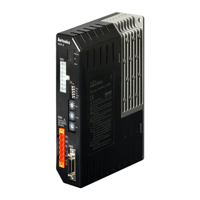
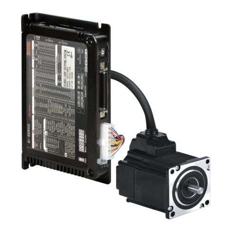
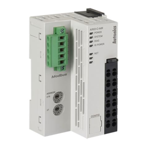
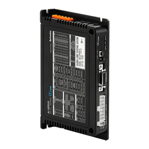
Autonics TM Series User manual

TM Series
Features
Manual
Comprehensive Device Management Program (DAQMaster)
Ordering Information
Multi-Channel (4 Channel / 2 Channel) Modular Type PID Control
※
※1
No communication and power supply for expansion modules
required by using side connectors: Max. 31 units (124 channels / 62 channels)
※
※ CT
Ⅲ
TM 4 N 2 R B

Multi-channel Modular Type PID Control
(A)
Photoelectric
Sensors
(B)
Fiber
Optic
Sensors
(C)
Door/Area
Sensors
(D)
Proximity
Sensors
(E)
Pressure
Sensors
(F)
Rotary
Encoders
(G)
Connectors/
Sockets
(H)
Temperature
Controllers
(I)
SSRs / Power
Controllers
(J)
Counters
(K)
Timers
(L)
Panel
Meters
(M)
Tacho /
Speed / Pulse
Meters
(N)
Display
Units
(O)
Sensor
Controllers
(P)
Switching
Mode Power
Supplies
(Q)
Stepper Motors
& Drivers
& Controllers
(R)
Graphic/
Logic
Panels
(S)
Field
Network
Devices
(T)
Software
Specifications
※℃℃
℃
℃℃
※℃
※
※
TM2 TM4
※1
℃
※2
℃℃℃
℃
※
℃℉℃℉
℃℉
㎲
℃℃
※3

TM Series
Dimensions
Unit Description
5. Indicators
●TM2 Series
※
※
※
※
6. Communication address setting switch (SW1):
7. Communication address group switch (SW2):
8. Lock switch:
9. Rail Lock:
10. END cover
※1
※2
※3
※4
※5
※1
※2
※3
●TM4 Series
1. Sensor input connector
2. Control output connector
3. Power/Comm. terminal
4. PC loader port
※
4
6
2
3
5
9
87
10
1
※

Multi-channel Modular Type PID Control
(A)
Photoelectric
Sensors
(B)
Fiber
Optic
Sensors
(C)
Door/Area
Sensors
(D)
Proximity
Sensors
(E)
Pressure
Sensors
(F)
Rotary
Encoders
(G)
Connectors/
Sockets
(H)
Temperature
Controllers
(I)
SSRs / Power
Controllers
(J)
Counters
(K)
Timers
(L)
Panel
Meters
(M)
Tacho /
Speed / Pulse
Meters
(N)
Display
Units
(O)
Sensor
Controllers
(P)
Switching
Mode Power
Supplies
(Q)
Stepper Motors
& Drivers
& Controllers
(R)
Graphic/
Logic
Panels
(S)
Field
Network
Devices
(T)
Software
TM2 Series
TM4 Series
※
Connections And Block Diagram
※
※
※
SCM-US (USB to Serial converter)
RS485 A (+)
RS485 B (-)
N.C
PLC
GP-S070
GP-S057
GP-S044
<RS485 communication support external device>
SOURCE
24VDC 5W
SCM-US48
(USB to RS485 converter)
SCM-38
(RS232C to RS485 converter)
RS232C
Serial
PC

TM Series
[Removal method]
①
②
[Installation method]
①
②
DIN Rail Installation
①
②
①
②
※ Install the units vertically. ※ Use end plates (sold separately, not available from Autonics) to
x rmly.
TM - 2 B
(basic module)
TM - 2 E
(expansion module)
TM - 2 E
(expansion module)
①
②
③
④
※
① ②
● Connector connection
Bolt Inserting
● Multi module connection
Installation
①
①
②
②
①②
③
③
③
④
⑤

Multi-channel Modular Type PID Control
(A)
Photoelectric
Sensors
(B)
Fiber
Optic
Sensors
(C)
Door/Area
Sensors
(D)
Proximity
Sensors
(E)
Pressure
Sensors
(F)
Rotary
Encoders
(G)
Connectors/
Sockets
(H)
Temperature
Controllers
(I)
SSRs / Power
Controllers
(J)
Counters
(K)
Timers
(L)
Panel
Meters
(M)
Tacho /
Speed / Pulse
Meters
(N)
Display
Units
(O)
Sensor
Controllers
(P)
Switching
Mode Power
Supplies
(Q)
Stepper Motors
& Drivers
& Controllers
(R)
Graphic/
Logic
Panels
(S)
Field
Network
Devices
(T)
Software
※
※
※
℃ ℉
※1
※2
Input Sensor Type And Temperature Range
Error Display
※
※

H-16
TM Series
Communication Setting
When changing communication address via the Power/Comm. terminal, resupply the power.
Set the communication address by the communication address setting switch (SW1) and Communication address group switch (SW2).
When setting as 0, it does not operate communication.
(setting range: 01 to 31, factory default: [SW1] 1, [SW2] +0)
It is for parameter setting and monitoring via external devices (PC, PLC, etc.).
Interface
Caution for Communication Address Setting
Communication Address Setting
※It is not allowed to set overlapping communication address at the same communication line.
Use twisted pair wire for RS485 communication.
Comm. protocol Modbus RTU Comm. distance Max. 800m
Connection type RS485 Comm. speed 2400, 4800, 9600 (default), 19200, 38400 bps
Application standard Compliance with EIA RS485 Start bit 1-bit (xed)
Max. connection 31 units (address: 01 to 31) Data bit 8-bit (xed)
Synchronous method Asynchronous Parity bit None (default), Odd, Even
Comm. method Two-wire half duplex Stop bit 1-bit, 2-bit (default)
SW1
SW2 0123456789ABCDEF
+0
+16
00 01 02 03 04 05 06 07 08 09 10 11 12 13 14 15
+0
+16
16 17 18 19 20 21 22 23 24 25 26 27 28 29 30 31
Application of system organization
※It is recommended to use Autonics communication converter; SCM-US48I (USB to RS485 converter, sold separately),
SCM-38I (RS232C to RS485 converter, sold separately), SCM-US (USB to Serial converter, sold separately).
Please use twisted pair wire for RS485 communication.
B(-)
B(-)
ON OFF
A(+)
A(+)
A(+) B(-) A(+) B(-) A(+) B(-)
Terminating resistance
(100 to 120Ω)
RS485
DEVICE
#1
RS485
DEVICE
#2
RS485
DEVICE
#30
RS485
DEVICE
#31
Computer
RS232C
or USB
Comm.
converter
RS485

Multi-channel Modular Type PID Control
(A)
Photoelectric
Sensors
(B)
Fiber
Optic
Sensors
(C)
Door/Area
Sensors
(D)
Proximity
Sensors
(E)
Pressure
Sensors
(F)
Rotary
Encoders
(G)
Connectors/
Sockets
(H)
Temperature
Controllers
(I)
SSRs / Power
Controllers
(J)
Counters
(K)
Timers
(L)
Panel
Meters
(M)
Tacho /
Speed / Pulse
Meters
(N)
Display
Units
(O)
Sensor
Controllers
(P)
Switching
Mode Power
Supplies
(Q)
Stepper Motors
& Drivers
& Controllers
(R)
Graphic/
Logic
Panels
(S)
Field
Network
Devices
(T)
Software
Sold Separately
Communication converter
℃
CSTC-E80LN
CSTC-E200LN
※
※
Current transformer (CT)
※
Current ratio: 1/1000
Wire wounded resistance: 31Ω±10%
※
Current ratio: 1/1000
Wire wounded resistance: 20Ω±10%
℃
SCM-38
(RS232C to RS485 converter)
SCM-US48
(USB to RS485 converter)
SCM-US
(USB to Serial converter)
※
Display units (DS/DA-T Series)
DS/DA-T Series
(RS485 communication input type display unit)
DS16- T DS22/DA22- T DS40/DA40- T DS60/DA60- T

TM Series
Proper Usage
Simple failure diagnosis
● LED indicators flash (for 0.5 sec. in turn), or external
device displays OPEN.
● Output does not operate normally.
● External device receives no-response or abnormal
data.
● Communication does not work between TM and
external device
Caution during use
Ⅱ
Other manuals for TM Series
6
Table of contents
Other Autonics Control Unit manuals

Autonics
Autonics AiC-D Series User manual

Autonics
Autonics ARIO Series User manual

Autonics
Autonics AiSA-D Series User manual

Autonics
Autonics AiCA Series User manual

Autonics
Autonics ARIO-C-MR User manual

Autonics
Autonics AiSA-D Series User manual

Autonics
Autonics AiC Series User manual

Autonics
Autonics AiC-CL Series User manual
Popular Control Unit manuals by other brands

YASKAWA
YASKAWA JEPMC-OP3C01-E instructions

Moxa Technologies
Moxa Technologies NPort Z2150 Quick installation guide

urmet domus
urmet domus ALPHA 1168/50 installation manual

Rohm
Rohm LAPIS Semiconductor ML22Q663 manual

Skipper
Skipper SB-100-SA Installation and operation manual

VAT
VAT 111 Series Installation, operating, & maintenance instructions