Q-3
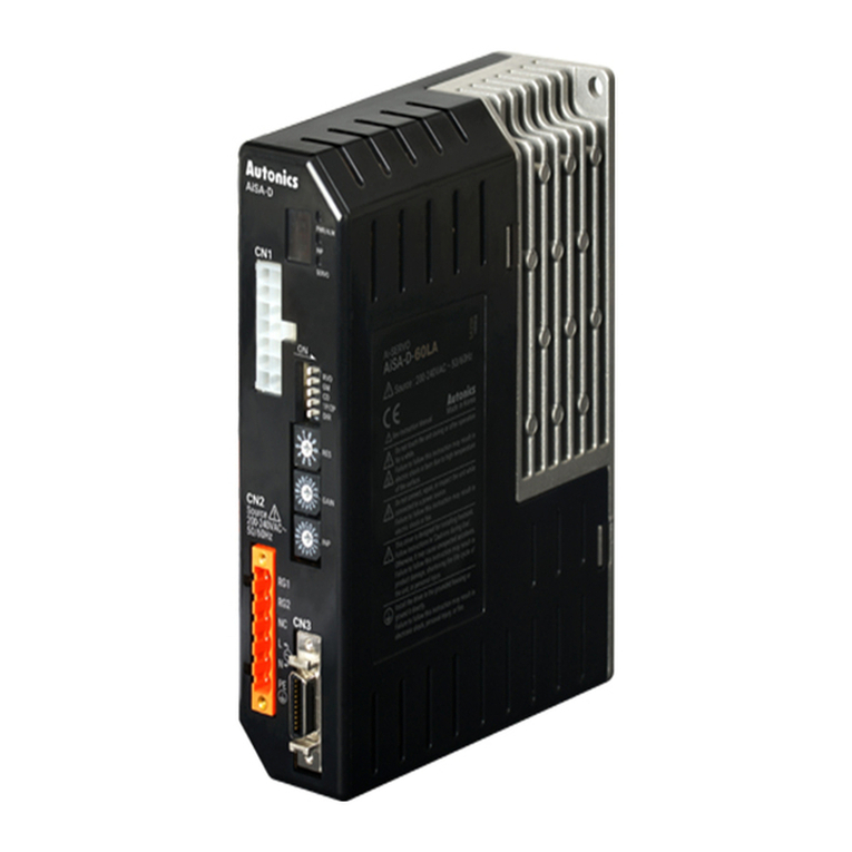
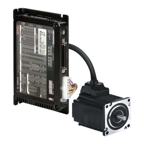
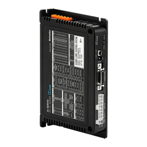
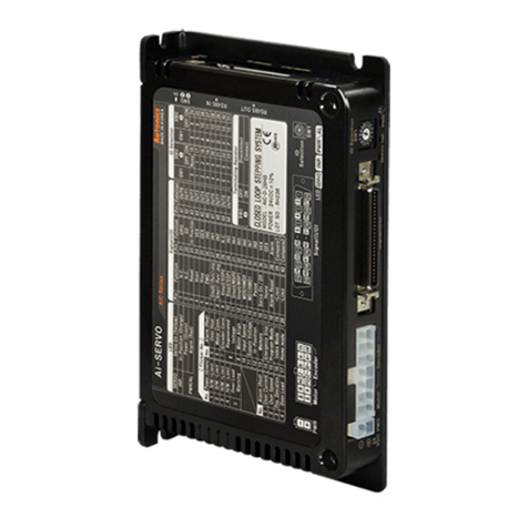
AC Type 2-Phase Closed-Loop Stepper Motor Driver
(A)
Photoelectric
Sensors
(B)
Fiber
Optic
Sensors
(C)
Door/Area
Sensors
(D)
Proximity
Sensors
(E)
Pressure
Sensors
(F)
Rotary
Encoders
(G)
Connectors/
Connector Cables/
Sensor Distribution
Boxes/Sockets
(H)
Temperature
Controllers
(I)
SSRs / Power
Controllers
(J)
Counters
(K)
Timers
(L)
Panel
Meters
(M)
Tacho /
Speed / Pulse
Meters
(N)
Display
Units
(O)
Sensor
Controllers
(P)
Switching
Mode Power
Supplies
(Q)
Stepper Motors
& Drivers
& Controllers
(R)
Graphic/
Logic
Panels
(S)
Field
Network
Devices
(T)
Software
Ordering Information
Specifications
AiSA Series
Set Driver Motor
AiSA-60MA AiSA-D-60MA AiA-M-60MA
AiSA-60LA AiSA-D-60LA AiA-M-60LA
AiSA-86MA AiSA-D-86MA AiA-M-86MA
AiSA-86LA AiSA-D-86LA AiA-M-86LA
Series
Item
Category
Motor frame size
Motor length
Encoder resolution
Ai 60D M A
60 60×60mm
86 86×86mm
A10,000PPR (2,500PPR×4-multiply)
M82.8mm
L103.8mm
M94.9mm
L109.4mm
DDriver
AAC Power
SStandard
Ai Articial intelligence
S A
Power
Model AiSA-D-60MA AiSA-D-60LA AiSA-D-86MA AiSA-D-86LA
Power supply 200-240VACᜠ50/60Hz
Power
consumption
STOP※1Max. 60W Max. 65W Max. 70W
Max. during
operation※2Max. 160W Max. 220W Max. 250W Max. 300W
Max. RUN current※32.0A/Phase
STOP current 20% or 30% of max. RUN current (factory default: 30%)
Rotation speed 0 to 3000rpm
Resolution 500 (factory default), 1000, 1600, 2000, 3200, 3600, 5000, 6400, 7200, 10000PPR
Motor GAIN Within the range of motor gain: 1 to 32
In-Position Within the range of Fast response: 0 to 7 or Accurate response: 0 to 7
Pulse input method 1-pulse or 2-pulse input (factory default) method
Motor rotation direction CW (factory default), CCW
Status display ● Power/Alarm indicator: green/red LED ● In-Position indicator: orange LED
● Servo On/Off indicator: blue LED ● Alarm/Status display part: red LED 7seg.
Input signal RUN pulse, Servo On/Off, alarm reset (photocoupler input)
Output signal In-Position, alarm out (photocoupler output),
Encoder signal (A, A, B, B, Z, Z phase, corresponding to 26C31) (line driver output)
Input pulse
specications
Pulse width CW, CCW: input pulse frequency duty 50%, Servo On/Off: min. 1ms, alarm reset: min. 20ms
Rising/Falling time CW, CCW: max. 0.5㎲
Pulse input voltage CW, CCW - [H]: 4-8VDCᜡ, [L]: 0-0.5VDC
Servo On/Off, alarm reset - [H]: 24VDCᜡ, [L]: 0-0.5VDC
Max. input pulse freq.※4CW, CCW: 500kHz
Input resistance 220Ω (CW, CCW), 10kΩ (Servo On/Off, alarm reset)
Insulation resistance Over 100MΩ (at 500VDC megger)
Dielectric strength 1,500VAC 50/60Hz for 1 min
Vibration 1.5mm amplitude at frequency of 10 to 55Hz (for 1 min) in each X, Y, Z direction for 2 hours
Shock 300m/s2 (approx. 30G) in each X, Y, Z direction for 3 times
Environment Ambient temp. 0 to 50℃, storage: -10 to 60℃
Ambient humi. 35 to 85%RH, storage: 10 to 90%RH
Approval
Protection structure IP20 (IEC standard)
Weight※5Approx. 900g (approx. 780g)
※1: Based on the ambient temperature 25℃, ambient humidity 55%RH, and STOP current 30%.
※2: Max. power consumption during operation. When changing the load rapidly, instantaneous peak current may increase.
The capacity of power supply should be over 1.5 to 2 times of max. power consumption.
※3: RUN current varies depending on the input RUN frequency and max. RUN current at the moment varies also.
※4: Max. input pulse frequency is max. frequency to be input and is not the same as max. pull-out frequency or max. slewing frequency.
※5: The weight includes packaging. The weight in parenthesis is for unit only.
※Environment resistance is rated at no freezing or condensation.
