Table of Contents
© Copyright Reserved Autonics Co., Ltd. vii
Table of Contents
Preface 3
User Manual Guide ........................................................................................................ 4
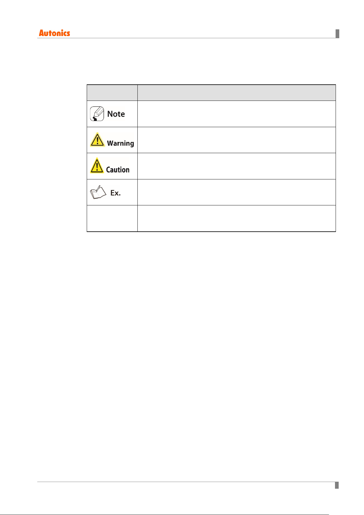
User Manual Symbols .................................................................................................... 5
Reference Manual for Each Configuration..................................................................... 6
Table of Contents ........................................................................................................... 7
1System Organization ................................................................................. 9
1.1 1:1 Communication.........................................................................................10
1.2 1:N Communication of Same Controllers.......................................................11
1.3 1:N Communication of Different Controllers...................................................13
1.3.1 1:1:1 Communication .............................................................................. 13
1.3.2 1:1:N Communication.............................................................................. 14
1.3.3 N:1:N Communication ............................................................................. 16
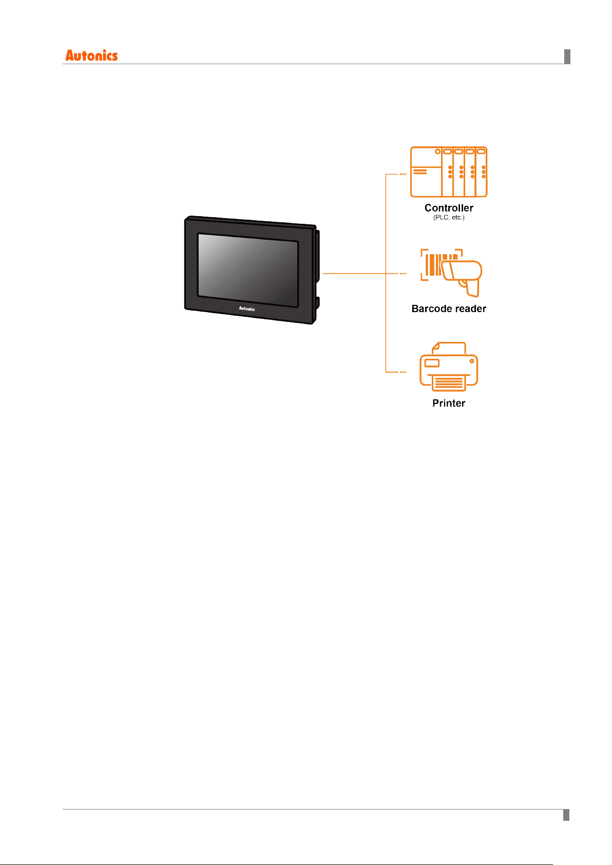
1.4 Barcode Reader, Printer Communication.......................................................17
1.4.1 Communication Configuration................................................................. 17
2Communication Configuration by Devices...........................................21
2.1 MITSUBISHI FX Series PLC Connection.......................................................21
2.1.1 Connection Support PLC Model ............................................................. 21
2.1.2 Connectable GP/LP Model...................................................................... 21
2.1.3 System Organization............................................................................... 22
2.1.4 Communication Cable............................................................................. 22
2.1.5 Available Device...................................................................................... 23
2.1.6 Monitorable Device in GP/LP .................................................................. 29
2.2 MITSUBISHI Position Control Module FX2N-10/20GM Series
Direct Connection ..........................................................................................30
2.2.1 Connection Support PLC Model ............................................................. 30
2.2.2 Connectable GP/LP Model...................................................................... 30
2.2.3 System Organization............................................................................... 30
2.2.4 Communication Cable............................................................................. 30
2.2.5 Available Device...................................................................................... 31
2.2.6 Monitorable Device in GP/LP .................................................................. 31
2.3 MITSUBISHI Q Series PLC Connection (LINK) .............................................32
2.3.1 Connection Support PLC Model ............................................................. 32
2.3.2 Connectable GP/LP Model...................................................................... 32
2.3.3System Organization............................................................................... 32
2.3.4 Communication Cable............................................................................. 33
2.3.5 Available Device...................................................................................... 33
2.3.6 Monitorable Device in GP/LP .................................................................. 35
2.3.7 MELSEC Q Series PLC Configuration .................................................... 36
2.3.8 GP/PLC Type Configuration in atDesigner, GP Editor ............................ 38
2.4 MITSUBISHI Q Series CPU Direct Connection .............................................39
2.4.1 Connection Support PLC Model ............................................................. 39
2.4.2 Connectable GP/LP Model...................................................................... 39
2.4.3 System Organization............................................................................... 40