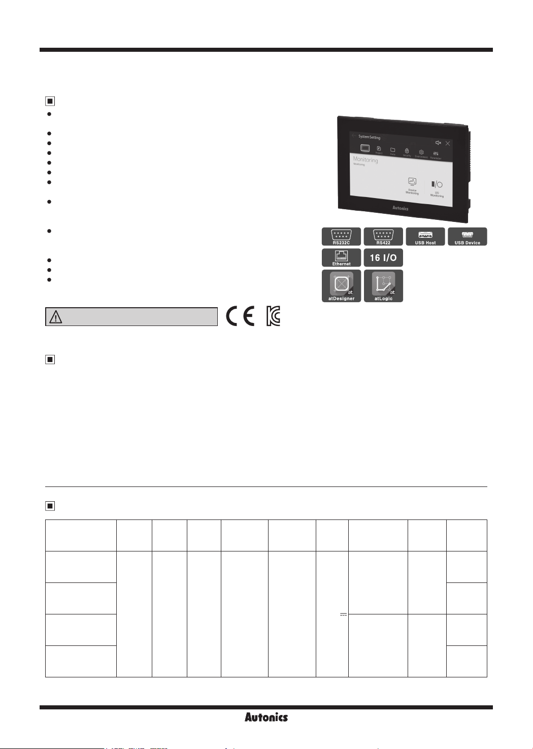
Advanced Type 7 inch Color Logic Panel
V-27
SENSORS
CONTROLLERS
MOTION DEVICES
SOFTWARE
(J)
Temperature
Controllers
(K)
SSRs
(L)
Power
Controllers
(M)
Counters
(N)
Timers
(O)
Digital
Panel Meters
(P)
Indicators
(Q)
Converters
(R)
Digital
Display Units
(S)
Sensor
Controllers
(T)
Switching
Mode Power
Supplies
(U)
Recorders
(V)
HMIs
(W)
Panel PC
(X)
Field Network
Devices
Drawing function
Function Description
Figure Line/Multi line/Rectangle/Round rectangle/Polygon/Circle/Fan/Chord/Arc/
Rectangle scale/Circle scale/Semicircle scale/Image/Text
Object
Lamp Displaying the value of the designated device in bit/word/multi lamp
Switch Switching the status of the designated device or object with bit/word/change screen/special/multi switch
Numeric input/display Displaying the value of the designated device/Inputting the value to the designated device in number (DEC,
HEX, OCT, BIN, REAL)
Text input/display Displaying the value of the designated device/Inputting the value to the designated device in text
(ASCII/Unicode)
Call window Calling a window screen according to the conditions on the value of the designated device
Message Displaying a message according to the conditions on the value of the designated device
Graph Displaying the value of the designated device in bar/pie/panel meter/statistic/RealTime trend/Logging trend/
RealTime distribution/Logging distribution graph
Clock Displaying time or date of the time
Recipe Editor Editing recipe (project)
Logging table Displaying the logging data (project) in a table
System logging table Displaying the system logging data (project) in a table
Alarm explorer Displaying the alarm group of alarm history (project) in a table
Alarm list Displaying the data of alarm history (project) in a table.
Data list viewer/editor Displaying/Editing the value of consecutive word device in a table
Option list Displaying the data of the designated device/Inputting data to the designated device in a combo box
Move coord. Displaying the object/Moving coordinate of the object according to the value of the
designated device
Project
Link device Reading/Writing the data between LP and controller (PLC) as long as setting according to the status of bit/
cycle condition
Flow alarm Displaying alarm in the flowing text at the set position, when meeting the alarming condition
Alarm history Saving data of alarming time, device, and information, when the value of the designated alarm-observing
device meets the set condition
Scheduler Executing a function (bit on/off/reversal, work value changing, script) according to the set condition (device/
cycle)
Recipe Reading the value of the multiple devices/Writing the value to the multiple devices at once
Logging Saving the value of the designated device, when meeting the condition (device/cycle)
System Logging Saving system operation information of LP in a log file
Script Writing Lua script by user
Logic function
Project Creating/Managing individual or multiple project. changing PLC type, printing, print setting
Edit Managing ladder/mnemonic editor, inserting/deleting line, managing rung, searching rung comment, search,
replace, nd step
Tool
Ladder tool: arrow, delete, vertical line, horizontal line, normally open contact, normally closed contact, rising input
contact, falling input contact, output instruction, rising output contact, falling output contact, set, reset, application
instruction, not instruction, register user defined function, user defined function
Program optimization, program checking, program checking options
View Ladder/Mnemonic, device/variable name, device name & comment, decimal/hexadecimal view, signed/unsigned
view, device/UW view, used devices, zoom in/out, font settings, color settings, toolbar
Online Connecting, disconnecting, download, upload, change mode, start monitoring, stop monitoring, read information,
change password, verify, change present value, system device, delete, firmware download, communication options
Debug Run, stop run, trace, insert/remove break point, stop debugging, debug-step, debug-line, debug-scan,
debug-1 scan, step in, step out, debug-bit, debug-word, forced I/O settings
window Cascade, horizontal tile, vertical tile, arrange icon, external program connection
Help Program information
Workspace
Program Ladder/Mnemonic program editor
Parameter
Common: output while debugging, operating condition for extended module, device latch range settings, default
lter value, time driven operation, time interrupt, timer range settings
Extension: input lter, external interrupt
Motion: common setting, operation setting, pattern setting
High speed counter
Variable/
Comment Managing and setting Variable/Comment by bit/word device
Monitoring Monitoring and registering device to monitor by bit/word device
Function