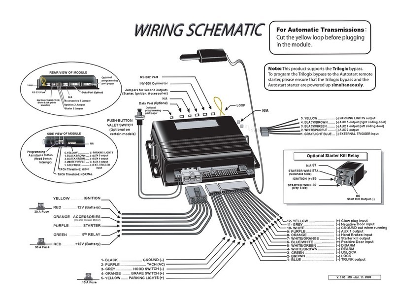
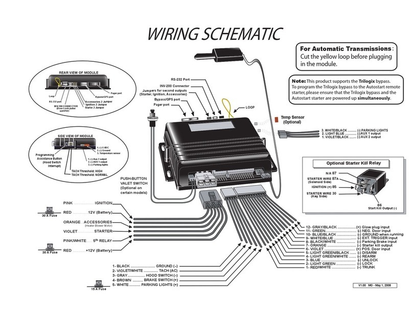
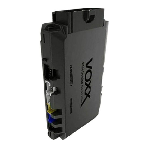
Autostart AS-6450VTW-FM Quick start guide
Other Autostart Car Alarm manuals
Autostart
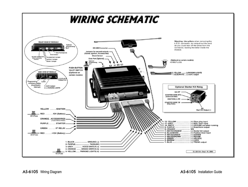
Autostart AS-6105 SH Quick start guide

Autostart
Autostart AS-1535 SH Quick start guide
Autostart
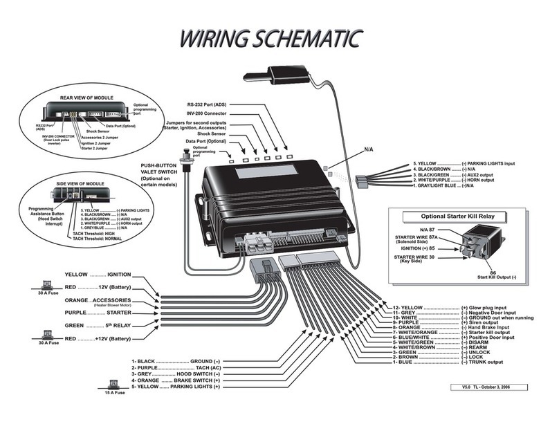
Autostart AS-6265i SH Quick start guide
Autostart
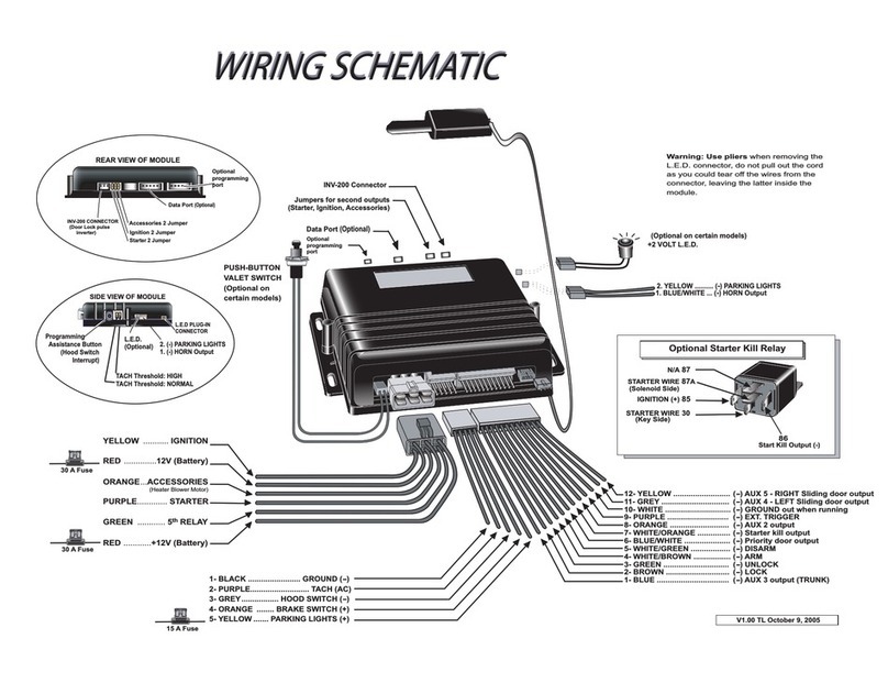
Autostart AS-1727 Quick start guide
Autostart
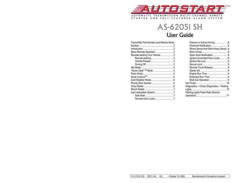
Autostart AS-6205i SH User manual
Autostart
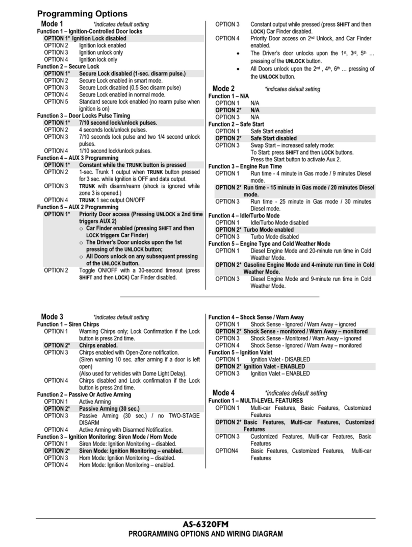
Autostart AS-6320 FM User manual
Autostart
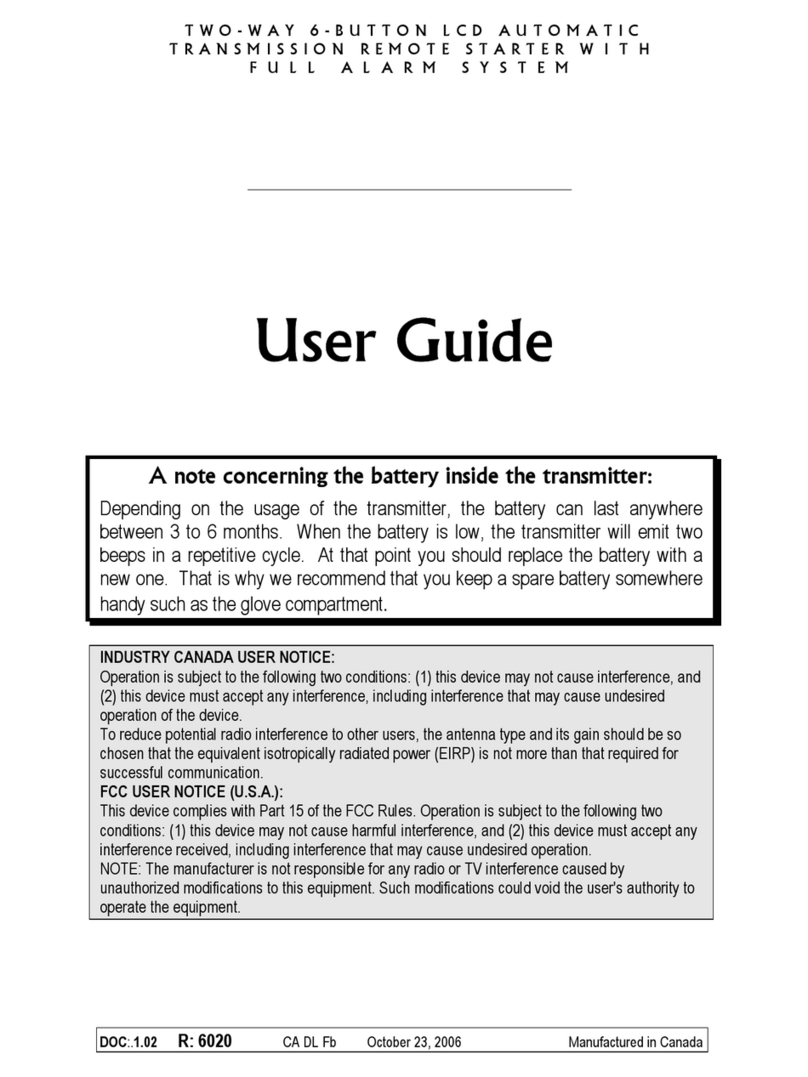
Autostart AS-6600i TW-FM User manual
Autostart
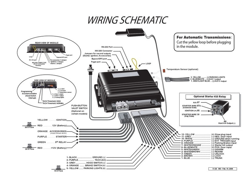
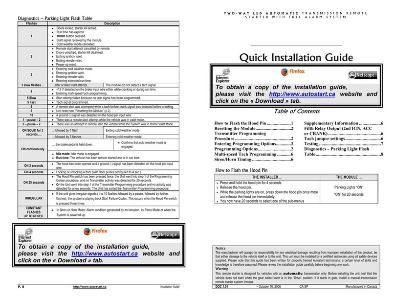
Autostart AS-2350vTW-FM Quick start guide
Autostart
Autostart AS-6400i TW-FM User manual
Autostart
Autostart AS-6660i TW-FM User manual
Autostart
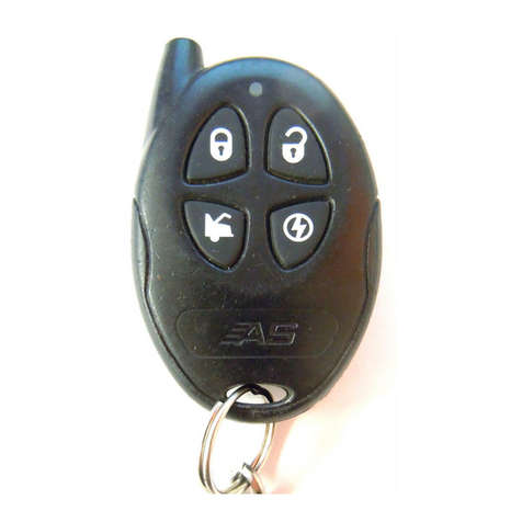
Autostart AS-6870 User manual
Autostart
Autostart ASL-150 User manual

Autostart
Autostart ASL-150 User manual

Autostart
Autostart AS-6105 User manual

Autostart
Autostart AS-6320 FM User manual
Autostart
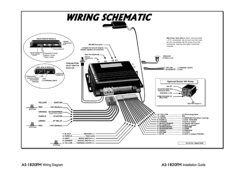
Autostart AS-1820 FM Quick start guide
Autostart
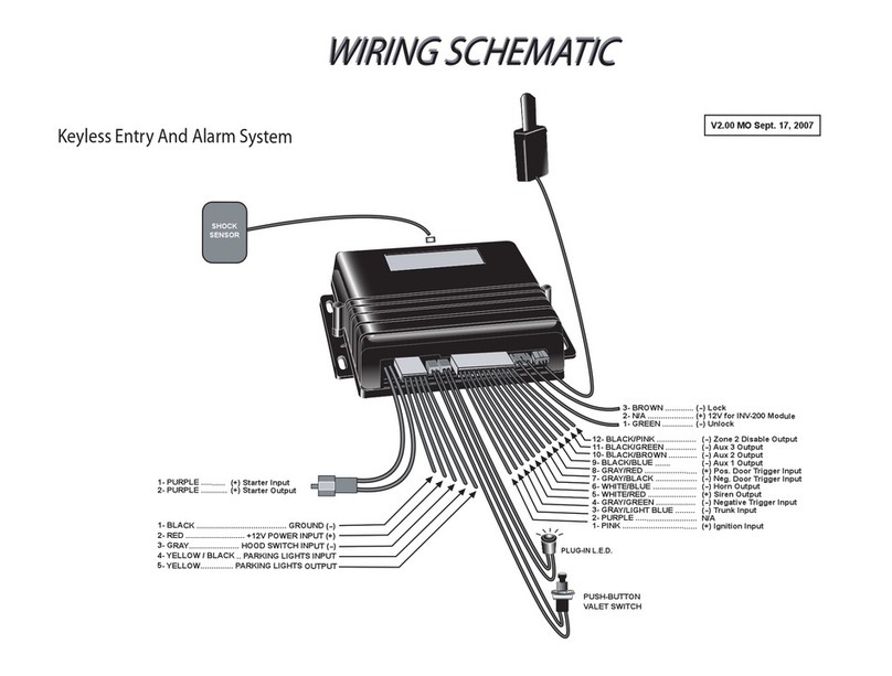
Autostart ASL-550TW-FM Quick start guide
Autostart
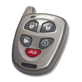
Autostart AS-1725i SH User manual
Autostart
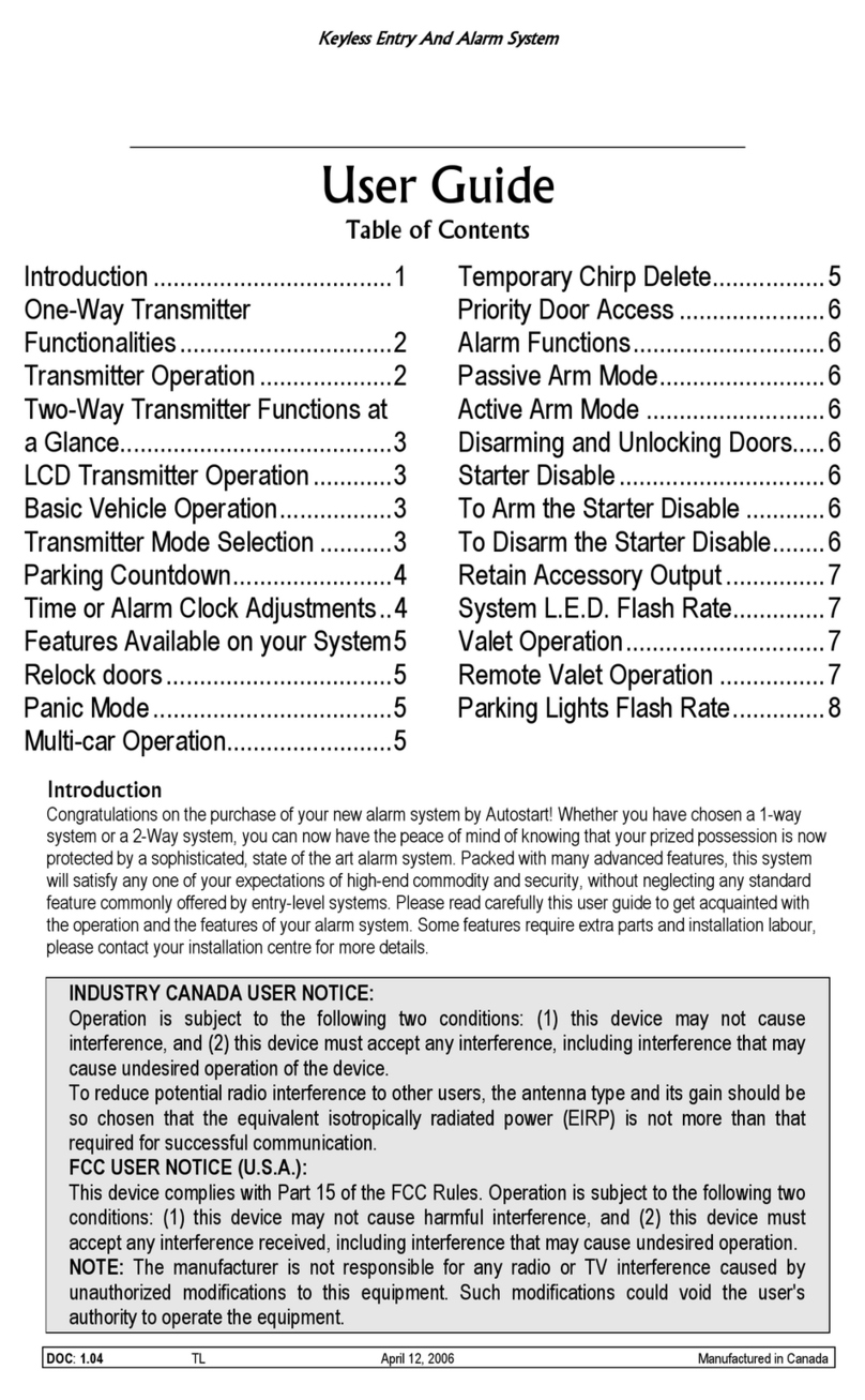
Autostart Keyless Entry And Alarm System ASL-500 User manual

Autostart
Autostart AS-6250V Quick start guide
Popular Car Alarm manuals by other brands

Federal Signal Corporation
Federal Signal Corporation Pathfinder Siren Series Installation and maintenance manual

Falcon
Falcon Predator XL3 Installer manual

Audiovox
Audiovox Auto Security XR91 Programming guide

Clifford
Clifford Sabre II owner's manual

CrimeStopper
CrimeStopper CS-8717 Wiring diagram

Scytek electronic
Scytek electronic Vectra X3 product manual
