AV-GAD EasyLoader AV-4044 Owner's manual

1
Ea s y L o a der
AV-4044, 4008 Pro
AV-4009 Dublo
AV-4016 Dublo
(for LCD keypads)
Integrated Alarm Control panel &
Communicator 8 zones
PSTN SMS Enabled
Installation and Operation Large Manual
Version 1.05 Preliminary
Edition I
This product is subject to continuous enhancements and therefore
specifications may be changed or altered without prior notice
Item: 4764E (A3BKE)
Rev 03: 04-May-2018

2
Table of contents
Introduction series AV-4000 LCD keypads ........................................................ 4
Tips to first time installer.................................................................................... 4
Revision changes .............................................................................................. 5
Keypad AV-707 short description ...................................................................... 5
2. Wiring devices to the panel .................................................................................7
2.1 Zone Wiring................................................................................................. 7
2.2 AV-4016 AV-4009 EOL Zone Wiring ........................................................... 8
2.3 Zone Wiring AV-4008 .................................................................................. 9
2.4 AV-816 Expander AV-4016, AV-208 for AV-4009........................................ 10
2.5 Keypad Wiring ............................................................................................. 10
2.6 Siren Wiring................................................................................................. 12
2.7 Remote Indication Terminals ....................................................................... 13
2.8 Wiring smoke detector................................................................................. 13
2.9 Remote Indications Testing ......................................................................... 14
2.10 Grounding Wiring & Lightning Protection................................................... 14
2.11 Back-Up Battery ........................................................................................ 14
2.12 AC or DC Power Supply ............................................................................ 14
3. Telephone Line and Central Station....................................................................15
3.1 Telephone Line & GSM Wiring .................................................................... 15
3.2 SVM – Synthesized Voice Module (SVM-40 and SVM-42) .......................... 16
3.3 Answering Machine Bypass......................................................................... 16
3.4 Telephone Line Test.................................................................................... 17
3.5 Contact ID Format ....................................................................................... 17
3.6 ID Codes for Communicator ........................................................................ 17
3.7 Remote Up and Download........................................................................... 17
4. Remote DTMF and remote Arming .....................................................................18
4.1 Remote Key and Wireless Arming & Disarming. Passive arming ................ 18
4.3 Remote Access via DTMF ........................................................................... 19
4.4 DTMF Commands ....................................................................................... 20
5. System Codes.....................................................................................................21
5.1 Description of main codes (32 codes).......................................................... 21
5.2 Enter user programming & Set New User Code .......................................... 21
5.3 SMS and dialer number entry by user.......................................................... 22
5.4 Installer Programming mode & Code change .............................................. 22
5.6 Auto Arming & Passive Auto Arming ........................................................... 22
5.7 Restore default codes.................................................................................. 23
6. LCD Keypad........................................................................................................23
6.1 Hold-Down Functions .................................................................................. 24
6.2 Zone bypass & Group Bypass (home mode) ............................................... 25
6.4 LCD Dual Keys Functions............................................................................ 27
6.5 Keypad Functions at location 200................................................................ 27
6.6 Keypad Sounder.......................................................................................... 29
6.7 LED Indicators............................................................................................. 30

3
7. New address Series 4000 ...................................................................................32
7.1 Systems parameters address ...................................................................... 32
7.2 Telephone and SMS address ...................................................................... 32
7.3 Events reported by the SMS module ........................................................... 33
7.4 Dialer reporting Programming locations....................................................... 35
8. Programming Sheet AV-4000 Dublo Version 1.05..............................................36
9. Step - By - Step Programming ............................................................................40
9.1 Reset System to Default Programming........................................................ 42
10. Powering Up & Wiring Diagram.........................................................................42
10.1 Before Powering Up .................................................................................. 42
11. Technical Specifications AV-4009, AV-4016................................................ 44
12. Troubleshooting ................................................................................................45
13. Wiring Diagram AV-4009............................................................................. 48
14. Wiring Diagram AV-4008............................................................................. 49
15. Wiring Diagram AV-4016............................................................................. 50

4
Introduction series AV-4000 LCD keypads
This is a full manual for series 4000 alarm panels supplied as reference (not with panel).
The alarm model suffix indicates the keypads compatibility: PRO is for LCD keypad; Dublo is for
LCD keypad and are expandable alarm panels.
AV-4044 PRO, AV-4008 PRO, AV-4009 & AV-4016 Dublo are compatible with Av-Gad LCD
keypads (AV-705, AV-706, AV-707).
In series 4000 all alarm panel models share the same programming table, provides faster and
simpler way to handle and programming for the installer.
Dials to six phone numbers
Dials and reports to two different central stations
Sends SMS messages via PSTN (saves the SIM card and GSM fee) to four numbers
Signal test to central station in few modes
Added special outdoor detectors zone, named Pulse Count zone
Now with 32 users codes
The AV-4009 & AV-4016 Dublo alarm and events sent by SMS (via PSTN line that supports
SMS) without programming. Examples: "Zone 1" during alarm the SMS received by user quoted
as "Zone 1", or if low battery detected “Low Battery” SMS is transmitted. SMS selection is
optional.
Series 4000 been revised for higher security when using remote PC and remote DTMF in order
to prevent criminal system tampering.
Pay attention to new default programming setting.
Tips to first time installer
If you are a first time installer, do not hook up any remote sensors at first. The most common
confusion comes about when the alarm will refuse to arm, because a zone is “troubled”.
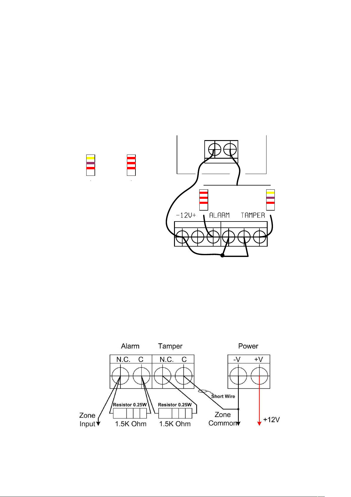
Complete the power supply, siren, keypad and strobe wiring, and for the moment connect ALL
the zone terminals to –V. This will simulate a system with all zones looped out through closed
switches. The alarm is supplied already programmed with an “average” list of settings (default)
and can be used straight away, a few of the program locations may have to be changed to suit
the actual sensors and output devices used.
The AV-4044 Pro, AV-4008 Pro, AV-4009 & AV-4016 Dublo are compatible with LCD keypads,
don’t use or mix LED keypads.
Read this manual carefully, it looks complicated, but all the information is there
Do not power up with battery! Use the AC power for start and testing. Programming code is 1994
To start with: Hook up the keypad, connect all zones to –V or apply resistors for 8 zone mode, power-up by
applying AC only
In case the keypad displays ‘No communication’ and keys not respond verify the minus (-V) wire and other
keypad connection. In LCD panels enter # after the password or programming entry.
Arm and disarm the system, when the Status LED light (not blinking), enter your master code; 1234
Try the hold-down functions. Hold each key for approximately 2 seconds
Set the system time by holding-down key ‘0’ then ‘1’, enter time in 24H format, blinking H stop
The default programming is set for siren alarm device that requires 12V to alarm (Bell Mode)
System dialer is noisy? You need ADSL filter. Check if the PSTN line carries ADSL signals
Make sure you are using the Earth terminal for Grounding; it is not a minus terminal
Typing six erroneous codes will lock the keypad keys for 30 seconds
Fast test: Verify “Dial LED" Self-Test at Initialization (STI) - Blinks for the first 50 seconds after power on,
confirms panel is operative, from keypad wait to six beeps to confirm communication OK.
In program mode press 200 and # to display control panel type & software version

5
Revision changes
Date Version Contains
05-Apr-2014 1.00 First published
02-Jan-2015 1.10 Added features
14-Oct-2015 1.10 Updated programming table
10-May-2018 Added software version check procedure
Keypad AV-707 short description
F i g u r e 1 : A V - 7 0 7 L C D k e y p a d d e s c r i p t i o n
Common Terms in this Manual
‘SHUNT‘ and ‘BYPASS’ are interchangeable terms
Program Mode - Enables features programming, Programming is displayed, alarm is
disabled
Use Mode – System is disarmed and not in alarm or program mode
AV-706 and/or AV-707 is identical in operation

6
Standard Keypad functions are accessed by pressing keys (short press). The 1 to 0
keys used for Arming/Disarming (ON/OFF), Zone Shunt (Bypass) and other
programming
functions.
A short beep confirms each key press.
A short press on keypad key accesses the following special functions:
5
Chime Instant Arming, by pressing key ‘5’ (requires programming).
0
Shunt Zone Bypass, by pressing key ‘0,’ followed by entering the Zone number/s
Group Bypass explained in the keypad section.
For full details refer to the keypad section in this manual and the LED keypad manual.
The series 4000 boards carries a specific identification label (refer to wiring diagram)
that shows the software version and panel type.
Electronic Fuse Overview
The Electronic Fuse device included as a series element in electric circuit. In response to an over current it
protects the circuit by going from a low-resistance to a high-resistance state that reduces the current to a level
that’s safe for the circuit elements. The change in resistance is the result of a rapid increase in the temperature
of the device. Like traditional fuses, Electronic Fuse devices interrupt the flow of dangerously high current.
However, unlike traditional fuses, they automatically reset after the fault cleared and power to the circuit
removed. Because they are solid-state, Electronic Fuses are also better able to withstand mechanical shock and
vibration, and provide reliable protection in a wide variety of applications. In case of over current, carefully touch
the fuse body (yellow round disc), hot body means the Electronic Fuse in protection mode, disconnect the load
and wait 2-3 minutes until the fuse body get cooler.

7
2. WIRING DEVICES TO THE PANEL
2.1 Zone Wiring
Your system provides two ways of zone wiring: None EOL resistor loop (factory default),
EOL resistor loop only for zone 4 and 8. The EOL loop protects the zone lines against
tampering.
F i g u r e 2 . 1 : N o n e E O L m o d e z o n e wi r i n g
Maximum zone wiring length is 200 meters using 0.5-mm2 wires, EOL mode wiring is
highly recommended.
Note: ‘Zone’ and ‘Sector’ are interchangeable terms in this manual.
An EOL zone will report Tamper alarm in case of zone shorting (if it has been EOL
programmed). For connecting N.O. zones, programming is required, refer to address
304. Do not connect few sensors to one zone in EOL mode.
Av-Gad Panel
-V Z4
Eye-Spy II
PIR
Colors
2.2K
Colors
4.7K
2.2K Resistor
Red
Red
Red
Yellow
Purple
Red
F i g u r e 2 . 3 : E O L m o d e z o n e wi r i n g ( R e q u i r e s p r o g r a m m i n g )

8
2.2 AV-4016 AV-4009 EOL Zone Wiring
The AV-4009 & AV-4016 Dublo board carries a specific identification label (refer to
wiring diagram) that shows the version and panel model.
The AV-4009 & AV-4016 are programmed as none EOL zone by factory default. The
zones are referred to –V. Connect two wires to the same terminal, one wire in series with
the 2.2.K resistor and the sensor contacts (relay), the other wire in series with 4.7K
resistor and other contacts.
Av-Gad 3000
Series panel
-V Z1
Eye-Spy II
PIR
2.2K 4.7K
Notice wires to -V
Colors
2.2K
Colors
4.7K
Red
Red
Red
Yellow
Purple
Red
F i g u r e 2 . 3 : E O L m o d e z o n e wi r i n g
The 2.2K resistors are wired with alarm zones, the 4.7K are wired with the Tamper zone.
Some countries are used to different double-pole wiring as shown in figure 2.4. For this
wiring, follow the drawing. European double-pole wiring requires 1.5K resistors (1.5K
resistors not supplied).
F i g u r e 2 . 4 : European Double-Pole wiring drawing

9
2.3 Zone Wiring AV-4008
Your system provides two ways of zone wiring: None EOL resistor loop (factory default),
EOL resistor loop only for zone 4 and 8. The EOL loop protects the zone lines against
tampering.
In AV-4008 zone 4 and/or zone 8 are capable being an EOL zone by setting the PCB
jumpers as the table below show. Programming is not required.
If EOL mode is selected install the EOL resistor (2.2K or 4.7K/0.25 or 0.5W) inside the
detection device (e.g. PIR, Magnetic Switch).
F i g u r e 2 . 2 : E O L m o d e P C B j u m p e r s e t t i n g s
Maximum zone wiring length is 200 meters using 0.5-mm2 wires, EOL mode wiring is
highly recommended.
Note: ‘Zone’ and ‘Sector’ are interchangeable terms in this manual.
An EOL zone will report Tamper alarm in case of zone shorting (if it has been EOL
programmed). For connecting N.O. zones, programming is required, refer to address
042. Do not connect few sensors to one zone in EOL mode.
Zone 4 JP6 JP3
Not EOL Not EOL
2K2 Not EOL
Not EOL 4K7
2K2 4K7
AV-4008 EOL mode zone 4/8
Zone 8

10
2.4 AV-816 Expander AV-4016, AV-208 for AV-4009
C10
++
++
C13
C15C16
C17
+BATTERY
-BATTERY
J1
R34
R35
R42
R43
R97
R98
R101R102
U3
VA1
VA2
VA3
C11
+
D2
D3
D4
D5
R22
R36
U7
D25
R62
R20
R26
D1
D10
Q5
D32
+12V
BAT. FUSE D9
D21
R51
R53
RF4
VA9
R59
D20
Q1
D19
R40
RN1
R60
D18
-12V
U2
U1
R16
R14
R13
R12
R11
R10
R9
R8
R7
R6
R5
R4
R3
R2
R1
C1
AV-GAD AV816
J1
Figure 2.5: Sixteen Zone AV-816 Expander W iring
Mounting
Place the AV-816 board on the left side of the AV-4016 board as the drawing shows.
Use two screws to tighten the AV-816.
The AV-208 fits the AV-4009 Dublo, locate the board in the left side f the board, refer to
the wiring diagram (last section in the manual).
Connection
Make sure power and battery are disconnected.
Plug the wires connector of AV-816 to J1 socket at the AV-2016, refer to figure 2.5
drawing.
2.5 Keypad Wiring
Up to five AV-706 or AV-707 Keypads can be connected to series 4000 Control Panels.
When few keypads are connected, wire each one directly to the panel, not from one
keypad to the other. Refer to drawing in next page.

11
When using few keypads connect them in parallel. Each keypad has four terminal wires:
(+) Power, connect to + Aux. Power System Data, connect to OR
(–) Power, connect to – Aux. Power System Strobe, connect to YE
F i g u r e 2 . 5 : W i r i n g m o r e t h a n o n e k e y p a d
Wire length for each Keypad should not exceed 100 meters (when using 0.5 mm2
wires).
For longer than 100 meters keypad wiring, contact manufacturer's consultant.
For AV-706/707TP (keypad with tamper) run five (5) wires. Connect the TMP terminal to
a 24H or Tamper zone.
Power at Keypad should be a minimum of 11.5 Volts.
IMPORTANT! Never run Keypad wires alongside telephone wires, high voltage
wires, or transmitting antennae. Wire the keypad wires separately and not in same
cable with other devices (telephone, PIR etc.)
For proper connection, refer to wiring diagrams at the end of the manual.
F i g u r e 2 . 6 : W i r i n g k e y p a d t o c o n t r o l p a n e l

12
2.6 Siren Wiring
The control panels (AV-4009, AV-4016) contains dual siren outputs, each protected by
Electronic Fuse.
It's highly recommended to use Av-Gad Bella Sirens to prevent inference and problems
caused by unknown sirens.
Siren should be outdoor type with a 12V DC, 0.7A or optional (requires programming)
speaker siren with minimum power of 15W, 8 Ohms Impedance. If two sirens wired as
internal and external consider the maximum current for both not to exceed 1 ampere.
Enclose the siren in a metal housing, with anti-tamper switch protection.
Warning, siren/s current should not exceed 1.0 Ampere
Bell mode is factory default; in Bell mode install a 12V DC siren, which contains sound
driver or electronic modules.
The alarm issued by the siren differs according to the type of zone.
Bell Mode’ converts Siren outputs into 13.6V DC outputs (no sound is issued).
Bell mode is applicable for driving self-powered sirens or bells, or combined sirens and
strobes.
F i g u r e 2 . 7 : W i r i n g s i r e n s t o c o n t r o l p a n e l
Output of 13.6V DC is issued at Bell mode. It’s recommended to use Bella sirens
series.
In Bell mode, connect only sirens, which contain sound driver or electronic modules.
Self contain Bell mode is programmable. This mode provides connection of Bells or
Sirens that requires 13.6V at idle and 0V during alarm.
Contact manufacturer's consultant before connecting higher power loads.
To connect self-contained sirens, Bells, and inner-oscillating sirens, Bella siren series
refer to programming table for Bell mode. Bella sirens support internal battery charge
and monitor for higher security.
For best security it’s recommended to install internal and external siren.

13
Siren configuration programming address
Address Feature Explanation
068 Siren test/beep upon arming Sounds a short beep to indicate arming
072 Bell mode Send 12V DC to drive the siren
073 Self contained siren Send 12V at idle, drop to zero V at alarm
092 Siren 3 beeps when disarm by
key
Sounds 3 short beeps to indicate
disarming
070, 071 Siren duration times Configures the siren times
2.7 Remote Indication Terminals - Max. 100 mA
Indication Application
ON (-V) on closing (Arming) or if cross-zoning feature selected
A1 (-V) during alarm from the programmed zone
A2 (-V) during alarm from the programmed zone
SLO (-V) during alarm from the programmed zone
SLO1 (-V) during alarm from the programmed zone
The A1 may be used to drive a low current Strobe Light (Xenon) that consumes up to
100 mA. Do not connect plain relays, sirens or similar loads to the outputs.
Home Automation feature: Momentary activation of A1 output for three seconds, via any
DTMF telephone command (address 074-2). See drawing sample.
In case other features are selected for the same output, this feature is not applicable.
F i g u r e 2 . 8 : W i r i n g r e m o t e i n d i c a t i o n o u t p u t t o p r o t e c t e d r e l a y
2.8 Wiring smoke detector
The alarm panel supports smoke detectors that powered by 12V and better include a
relay output. After alarm the smoke requires reset, done b power cut, add a AV-01 relay
as drawing shows. Program the zone as fire, set the output as smoke reset.
AV-01 Relay
module
1 to +12V
2 to -12V
COMN.C.
To panel output like A1
(supply -V on Reset)
Connect to
+12V
To panel -12V
To panel +12V
To zone input
(most use zone 8)
To -12V
AVP-400 Smoke
With internal relay
-V+V
Reset smoke relay
Figure 2.9: W iring smoke detector

14
2.9 Remote Indications Testing
To test the remote indication outputs without entering to alarm mode; enter to
programming mode (hold down 8, enter 1994, followed by #).
Testing ON output, enter 200 than 30 to enable, 200 than 31 to disable
Testing A1 output, enter 200 than 32 to enable, 200 than 33 to disable
To quit programming mode enter 999 than #.
2.10 Grounding Wiring & Lightning Protection
The control panel must be earth grounded for lightning protection to work effectively, and
in order to prevent RFI and EMI interferences. Connect the ground to a verified cold-
water pipe using a minimum 16 AWG (or larger) wire. Run the wire via the shortest
possible route.
System grounding is compulsory
Note: Connect the Ground wire, to the terminal. This is not a minus (-V).
Be careful of static discharge; before handling the main board touch a grounded
metal surface to discharge.
Before grounding the system, make sure to connect ground properly, check that ground
does not transfer high voltages.
In tropical areas order the Surgo protection module or specific models to fit.
2.11 Back-Up Battery
Make sure to connect the Battery in the correct polarity!
The system's Red wire is the positive pole (+) and the Black wire is the negative pole (-).
The battery will provide power back up in case of AC power failure.
Connect back-up battery to ensure proper operation of the system.
Recommended battery: 7 Amperes per Hour (AH), 12V (sealed lead acid) type.
Battery type 7 A/H backs up control panel and a single keypad for about 8 hours.
Series 4000 panels accommodates a battery of up to 12V – 9 A/H (max.).
An Electronic Fuse rated at 2.5A protects the battery.
Add a power supply for installation with over three LED keypad and/or if over ten
high current sensors included. Refer to AV-21, AV-40 power supply and charger.
2.12 AC or DC Power Supply
Each alarm panel requires AC 16V source (older 5003TER or 5005TER none polarity
devices) or DC 17V by new 5017TER. For solar panel (SL-2032) applications contact us.
When using DC sources make sure to connect the power in the correct polarity! When
solar panels removed connect other power source like 5017TER. Don't use higher
voltage power source.
When using 5017TER or SL2032 the (+) connect to the upper AC wires terminal and the
(-) to the lower AC marked terminal.

15
Solar Panel
SL2032
- + +Positive
-Negative
Notice
polarity
Wires box
At SL2032
+SIR-SIR KEY
5017TER
DC source
+Positive
-Negative
Alarm Panel
Board
Polarity
F i g u r e 2 . 1 0 : W i r i n g p o we r s u p p l y a n d s o l a r p a n e l
3. TELEPHONE LINE AND CENTRAL STATION
3.1 Telephone Line & GSM Wiring
Dialing sequence: 1st dials to central stations, 2nd send SMS, 3rd dials to standard
phones (wired or mobile). If central station not programmed sequence is bypass.
It’s recommended to connect the control panel to an independent telephone line, if a
device is in parallel with the alarm panel, this may grab the call first (like a message
answer/fax) during remote up and download and remote DTMF. Don’t connect fax or
answering machine in parallel on the same telephone line.
In AV-4009/4016 GSM if phone numbers programmed system dials them via PSTN,
send SMS via GSM. Dialing via central phone system (PBX), enter 9 (get line) hold down
0 (pause) that the number.
Default dialing mode is DTMF. At areas with low quality-noisy lines; PSTN Pulse Dial
(old dialing format) is optional, at Pulse Dial mode the default is European Make/Break
rate of 40/60 milliseconds (in Pulse dialing). Australia: Austel PSTN line is optional.
F i g u r e 3 . 1 : W i r i n g T e l e p h o n e ( P S T N ) L i n e

16
Dialing mode is programmable (refer to programming sheet addresses 084).
Connect the telephone line to ‘TEL-LINE’ terminal, if handsets connected to same line
connect them to ‘PHONES’, when system attempts to dial the ‘PHONES’ is
disconnected.
Do not connect to ISDN or other digital telephone system. Most ISDN converters contain
an Analog line; connect the Analog line of the ISDN to the panel TEL-LINE terminal.
If the PSTN is DSL/ADSL type connect a dedicated lien filter supplied by local Telecom
Company, or Av-Gad AV03 high end ADSL filter.
If GSM module is required: Use high end unit like AVG-13, AVG-16. Cut the jumper at
the PCB, located at the right-lower side of the PCB, see drawing at wiring diagram.
Consider that low quality GSM module cause great problems like wrong dialing, RF
interferences, wrong reporting to central station and disables the DTMF remote control
feature.
3.2 SVM – Synthesized Voice Module (SVM-40 and SVM-42)
The SVM-42 (latest model) and SVM-40 are Synthesized Voice Modules. The SVM is an
optional item (not supplied with the panel). The SVM allows the recording and playback
of two messages, with optional playback through an external speaker (not included) or
via the phone during alarm. The SVM is a high technology device, electronically stores
messages with or without power.
SVM-42 message duration is 40 seconds in total, CH1 and CH 2. The SVM contains an
on board microphone. For interfacing the SVM to your panel refer to the SVM manual.
AV-4000 GSM panels are not compatible with SVM-40 or SVM-42.
The SVM is a digital message source in Series 4000 Alarm Control Panels, telephone
dialers or in other applications. The SVM supplied audio is capable to drive audio
amplifier, message center, automatic dialer or other device.
When connected to series 4000 program the SVM to be activated per zone, refer to the
zone features section address 268, 272.
The ON output will trig channel 1 of the SVM and A1 output will trig channel 2. In panels
AV-4009, 4016 output A2 also can be used, refer to address 127.
For setting the message length refer to address 043, 044 recommended value 20. Set
042=00 for voice without siren sound before.
Follow the wiring procedures (included in SVM manual) simulate alarm (long 6 than long
7); the panel will dial first the central station telephone numbers, then dial to other
programmed numbers.
After dialing, the panel will trig the SVM to send the recorded message.
3.3 Answering Machine Bypass
For remote up and download, and DTMF remote control you need to call up the alarm
panel.
In case the alarm panel connected with fax or answering machine on the same
telephone line (not recommended) enable the Answering Machine Bypass or Answer
Now features (otherwise connection is impossible).
To enable the feature:
1. Program 1 at address 059
2. Program at least 24 seconds at address 057 (Ring Time Out)
To proceed: Dial to the control panel, count at least three rings and disconnect, dial
again after 10 seconds – the panel will answer at first ring.

17
When Answering Machine Bypass enabled, the control panel will answer at first ring if:
- There was a pause of at least 10 seconds from last ring
- The panel already counted at least three rings before the pause
- Number of rings to answer (at address 091) is less than 20
Notice: The panel will answer (in a normal mode) if there is no pause and the rings
counted exceed (or equal) the number programmed at 091.
3.4 Telephone Line Test
Series 4000 includes Telephone Line Monitor, refer to address 094: Time interval
between telephone line tests - in hours. Range between 00-24. When ‘00’ programmed
no test performed. Failure to get a dial tone when dialing will cause a "Phone Line Fault"
event.
In case you need an external telephone monitor order item: TLS (Tele-Spy).
3.5 Contact ID Format
All of series 4000 panels are able to send report for two separate central stations, address
017,018.
The GSM models are not reporting to central station by now (under process).
For Central Station (CS) reporting two telephone numbers are available, Tel. 2 (address
019) is main central station Tel. Number and Tel. 3 (address 020) is for 2nd central
station reporting, or as backup to the same CS.
Contact ID Format (known also as Ademco Express) is the fastest to program and
easiest to use communicator format for central station, with communication speed
achieved by the DTMF signaling.
When using Contact ID format, program only Central Station telephone numbers and the
subscriber ID; all reports will be automatically transmitted, with no need to program
anything else.
Step by step:
1. Address 019, 020 enter the central station (CS) telephone numbers
2. Address 030, 031 program 2 (set by default)
3. Address 021, 025 program the subscriber number, the CS will provide the ID, keep
always four digits
4. Address 034 determines the opening/closing report status
3.6 ID Codes for Communicator
Not available
3.7 Remote Up and Download
EasyLoad Introduction
The remote up and download feature enables fast and simple programming of
EasyLoader panels. Programming tables, codes and other features may be up &
downloaded from an on-site PC (DOS or Windows Mode) via telephone using Modem
and ‘EasyLoad’ software, which is supplied separately on a diskette. The control panel
contains a full-duplex modem that conforms to BELL 103 standard.

18
Installing EasyLoad on your Computer
The installation program will guide you, and will install EasyLoad automatically by
making a new directory called AVGAD, or one of your choices. The README 1st file
supplied with EasyLoad will help you operate the up and download program.
DOS old version: To start your EasyLoad: At the prompter ‘C:\AVGAD’ type ‘ESAV’; you
will be notified that some files are missing (the database). Answer ‘Yes’ to create them.
The main EasyLoad menu contains seven selectable fields, to enter main menus use the
arrows (right part of computer keypad) or by entering the field number. Using a mouse is
highly recommended.
The control panel modem is set by default to answer the PC after 10 rings - see
address 054. Hold down key 6 then hold-down key 1 for ‘Answer Now’ mode. In
address 091 enter 10 or higher (21 to 99 rings) in order to disable panel modem.
Configuring your Modem
First, verify that your modem is Bell 103, refer to manufacture data sheet.
Configure your modem port using the SET-UP entry from the main menu (field 7).
Specify the COM PORT, on which your modem is installed, making sure your mouse is
not on the same COM PORT. Do not use COM1 and COM3 or COM2 and COM4
simultaneously. If you cannot initialize modem, use the Auto Detect option. Av-Gad
supplies the proper mode, and inverter for USB computers.
The PC keyboard can also be used, e.g. Move from field to field using arrows (when
possible), the TAB key (forward), shift + TAB (backward), ALT key + highlighted letter.
Confirm input in text fields by hitting the ENTER (return) key. In order to select the
required field; hit the highlighted digit or letter.
Full instructions and latest features are enclosed in the EasyLoad software diskette.
Check the latest Windows EasyLoad.
Local Up and Download via PC (AV-232 adapter required)
Series 4000 alarm panels provides local up and download via RS-232 and modem.
When using the AV-232 interface (special RS-232 cable and interface connecting the
PC to the panel) set the panel to programming mode, ‘P’ is displayed; type 77 at
address 200 (i.e. type 20077) before attempting to establish connection.
When using the AV-232 the transfer rate is 8 times faster than through the modem. With
local PC, use the same procedures as described below. Maximum AV-232 length is five
meters. If your computer is using USB as serial interface order the RS-232 to USB
adapter, item AVUSB232.
4. REMOTE DTMF AND REMOTE ARMING
4.1 Remote Key and Wireless Arming & Disarming. Passive arming
The AV-4009 AV-4016 enables Arming and Disarming by remote momentary key-switch,
which is connected to ‘KEY’ and ‘- Aux. Power (Refer to Wiring Diagram). Cable set for
connecting to JP1 requires separately ordered.
When using remote key-switch, wire length should not exceed 10 meters.
A Momentary pulse (momentary trig) between ‘KEY’ terminals will Arm and Disarm the
control panel (close the ‘instant’ and ‘24H’ zones Prior to arming.)
System reverts to previous status with next momentary pulse. (Refer to Wiring Diagram.)

19
For Arming/Disarming via Wireless Radio Remote, connect receiver's relay to ‘KE’ and ‘-
Aux. Power’ terminals. Verify the receiver relay mode, momentary, or latch, and set
system accordingly.
In most cases the Key terminal is applicable for emergency Disarming – Short the key
terminal to -V. For remote arming with wireless remote transmitter use the AVS22 RF set
remote.
Zone 8 or 16 ("last" zone) may function (requires programming) as auxiliary remote key
input, programmable at address 089.
The Aux. key Arms without Home (group) mode, sounds siren beep when Arming (if
programmed), sounds siren beeps when Disarming (if programmed).
4.2 Passive Arming
Description: In case user want the system to be self armed if for certain time in the
protected area sensors not detected movement.
Passive arming if activated if all zones are close for and was active for a programmable
time (time without movement).
Time wait before arming is programmed at address 098. Time without movement 05 to
99 minutes, 00 = No passive arming
4.3 Remote Access via DTMF
General Description
Program address 109 to enable DTMF remote control.
Verify that your PSTN line support DTMF dialing, other important issue is that PSTN line
is at good condition. Adding GSM module or low quality ADSL filter may interfere DTMF
commands.
DTMF commands are available when the panel call your phone, or by calling the panel.
The DTMF remote control functions:
Check the status of the control panel (Armed/Disarm, Alarm in progress)
Arm or disarm the control panel
Bypass zones or clear all bypassed zones
Stop the dialer report during alarm
Momentary activate A1 (alarm) output for three seconds
Momentary activate SOL output for five seconds
First Alarm indication - by a number of beeps per zone, special tune for Panic alarm
The same options are available when a call is received from the control panel during an
alarm condition.
Keypad online confirmation and DTMF functions history
When the control panel detects the first DTMF key, five short beeps sound at the
keypads. The keypad activation shows the user at the remote site that a DTMF
connection takes place (in case of mistaken connection or similar).
During the remote access the keypad display DTMF status and all LEDs blink fast from
time to time.

20
When the call ends, the three short beeps sound at the keypads. When the user code is
in process, the keypad display shows a line for each code number entry (disclose the
code), then each DTMF number pressed show the received number.
History log: Each call, confirmed by a valid user code, is recorded in the events history.
Each "Arming/Disarming" is recorded in the events history.
Notes: 1. The keypad buzzer or other loud sounds may jam your DTMF entries, in case the
keypad is close to your DTMF telephone, during testing disable the buzzer.
2. When entering the DTMF commands wait for “quiet” period, if entering commands
during the system confirmation tunes, or other tunes the panel may miss the DTMF
entries.
The panel calls the user during alarm
When the control panel calls the user during alarm, it will first generate the siren sound
for about 30 seconds (to shorten this feature at address 045 “Tel. Mi. call Time”, to 30,
as default is 60 seconds). The siren sound will stop ten (10) seconds before the end of
the call and a greeting tune will be sounded, after the greeting tune enter your code
followed by #. To stop the dialer enter 6#, to get panel status enter 7#, to disarm the
panel enter 2#. Press 9# to end the process. To arm the system press 1 #
The control panel will answer the call after the number of rings programmed at address
054 (or following the “bypass answering machine" procedure).
4.4 DTMF Commands
Each command must be followed by the '#' key (Enter) in the remote phone. The control
panel waits 4 seconds between the keys typed. When this time expires, previous keys
input will be discarded.
The key '*' cancels previous input. It’s recommended to start with "learn" function [8X #]
to identify the various confirmation tune.
The commands:
[0 XX #] - Bypass zone (# is the Enter key), XX is Bypassed zone 01 to 32
To clear all bypassed zone: 099 #
The zone bypass command is valid only when the system is in Disarm mode, not valid in
Alarm mode.
[1 #] - Arm control panel. The control panel will be armed even with open zones. After
the arming, a confirmation tune followed by an "armed" tune will be sounded ("Armed"
tune: Short beep followed by a long tone).
The user can wait a few seconds to be sure that no alarm has been caused by open
zones. In this case, an Alarm tune (siren sound) will be sounded.
[2 #] - Disarm control panel. The control panel will be disarmed. A confirmation tune
followed by a "disarmed" tune will be sounded ("Disarmed" tune: Five short beeps).
[31 #] - Activates A1 output for 4 seconds (enabled by programming 122)
[33 #] - Activates SLO output for 3 seconds (enabled by programming 133)
[50 #] - Deactivates A2 output to stop Listen In (enabled by programming 128)
[51 #] - Activates A2 output for Listen In (enabled by programming 128)
[6 #] - Stop dialer. The dialer will stop calling the programmed telephone numbers. This
will affect only the current dialing process. A new alarm will re-start the dialer.
This manual suits for next models
3
Table of contents
Other AV-GAD Control Panel manuals
Popular Control Panel manuals by other brands

SILENT KNIGHT
SILENT KNIGHT IFP-1000 Basic operating instructions

Emerson
Emerson Appleton ALPN instruction manual

Bogen
Bogen ATP10 Specifications

Cooper Controls
Cooper Controls Greengate CK4-120NO Installation sheet

SEW-Eurodrive
SEW-Eurodrive DOP11C operating instructions

Honeywell
Honeywell MRP-2002 instruction manual