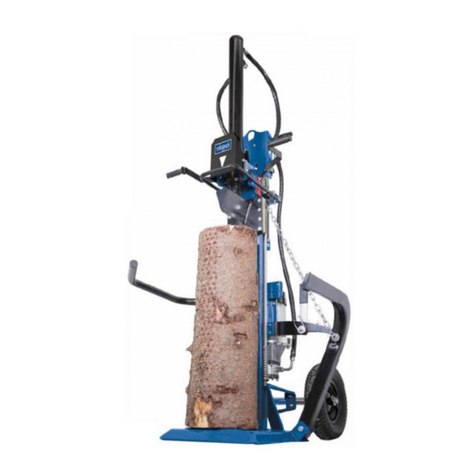
Avantco A21262 User manual

Log cutter/splitter ANNEX 2012 1
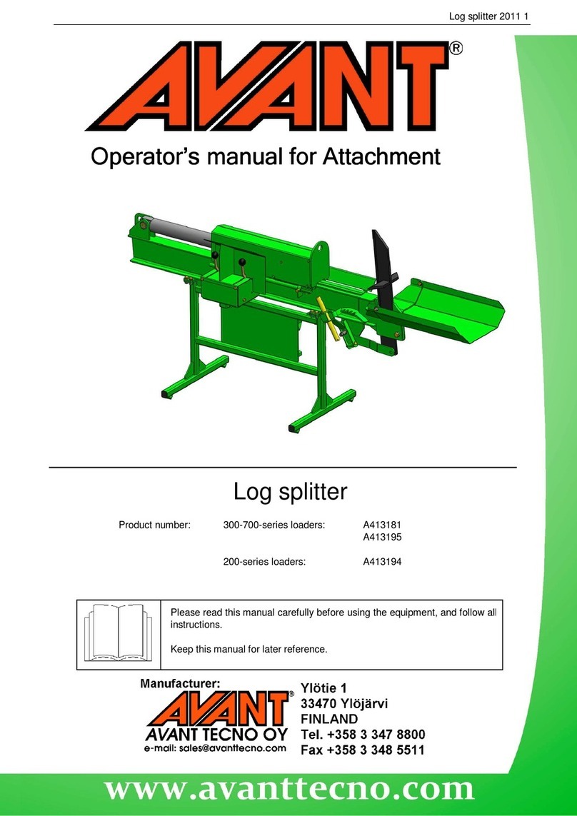
Log Cutter/Splitter
JAPA 300
Product number: 300-700-series loaders: A21029
200-series loaders: A21262
Annex
AnnexAnnex
Annex
for the original attachment’s
for the original attachment’sfor the original attachment’s
for the original attachment’s
Instruction Manual
Instruction ManualInstruction Manual
Instruction Manual
Please read carefully the original attachment’s instruction manual before
using the equipment, as well as this annex, and follow all instructions.
This annex for the operator’s manual includes specific information about the
use of the equipment with Avant multi purpose loaders.
Keep the original operator’s manual as well as this annex for later
reference.

CONTENTS
1. Foreword..................................................................................................................................3
2. Designed purpose of use .........................................................................................................3
3. Safety instructions for using the log splitter with Avant loaders.................................................4
4. Technical specifications ...........................................................................................................5
5. Assembly of the log cutter/splitter.............................................................................................5
5.1. Mounting the log cutter/splitter to the loader....................................................................................
5
5.2. Connecting and disconnecting the hydraulic couplings....................................................................
7
6. Operation.................................................................................................................................8
6.1. Setting up the log cutter/splitter.......................................................................................................
8
6.2. Use.................................................................................................................................................
8
7. Maintenance and warranty.......................................................................................................9
This manual uses the following warning symbols to indicate important points that must be taken into account
to reduce the risk of personal injury or property damage:
DANGER:
This safety symbol refers to important safety information in this manual. It warns of
an immediate hazard that could cause serious personal injury or property damage.
Read the warning text accompanying the symbol carefully and ensure that other
operators are also familiar with the warnings, since personal safety is at stake.
Note:
This notice symbol indicates information about the correct operation and
maintenance of the equipment.
Failure to observe the instructions accompanying the symbol can lead to equipment
breakdown or other property damage.
In addition to the safety instructions included in this manual, you must observe all occupational safety
regulations, local laws and other regulations concerning the use of the equipment. Due to continuous product
development, some of the details in this manual may differ from your equipment. We reserve the right to
change the contents of the manual without notification. This annex for the instruction manual is a translation
of the original Finnish version.

3(10)
1. Foreword
Avant Tecno Oy would like to thank you for your purchase of this attachment for AVANT multi purpose
loaders. The log cutter/splitter has been adapted for use with AVANT loaders by the original manufacturer of
the equipment.
The original manual, provided with the log splitter/cutter, includes the information of safe use of the equipment.
This annex for the manual includes important information of mounting and using the equipment with AVANT
loaders.
By familiarising yourself with the original operator’s manual and the additional instructions provided in this
annex, you ascertain your safety and ensure the reliable operation and long service life of the equipment.
Ensure that all persons using the loader and the log cutter/splitter have received proper guidance and
familiarised themselves with the manuals of the loader and attachment and all safety instructions before using
the equipment.
Keep this annex of the manual at hand throughout the service life of the equipment. If this annex for the
manual or the original operator’s manual is lost or damaged, you can request a new one from your nearest
AVANT dealer. If you sell or transfer the equipment, be sure to hand both parts of the manual to the new
owner.
This annex for the original instruction manual of
the log cutter/splitter machine does not cover all
of the instructions needed for safe operation of
the equipment. It is not meant to be distributed
separately. The original instructions manual,
provided with the machine, should be
considered as the main source of information
about the safety, use and the maintenance of
the equipment. This annex includes important
information about the use of the equipment
specifically with AVANT multi purpose loaders.
2. Designed purpose of use
The JAPA firewood machines are hydraulically operated attachments designed and manufactured to be
suitable for use with 200-700 –series AVANT multi purpose loaders. They are intended to be used by one
person at a time for cutting firewood and splitting it into halves or quarters. The log cutter/splitter cuts the log
with a chain saw blade to the adjusted length, and then the log is split with a hydraulic cylinder, which presses
the log against the splitting wedge.
The log cutter/splitter is meant to be attached on the AVANT loader during use. The attachment is powered by
the hydraulic outlet of the Avant loader. The log conveyor, shown in the original manual, is an optional extra.
Contact your AVANT dealer for further information about its availability.
Familiarise yourself with the instruction manual's instructions regarding service and maintenance. Demanding
repair and maintenance operations, such as hydraulic repairs, should be left for professional maintenance.
Please contact your AVANT retailer if you have additional questions about the operation or maintenance of the
equipment or if you require spare parts or maintenance services.

4(10)
3. Safety instructions for using the log splitter with Avant loaders
Please bear in mind that safety is the result of several factors. The loader-attachment combination is highly
powerful, and improper or careless use or maintenance may cause serious personal injury or property
damage. Due to this, you should carefully familiarise yourself with the manuals of both the loader and the
attachment before starting operation. Do not use the attachment if you have not completely familiarised
yourself with its operation and the related hazards.
•When mounting the log cutter/splitter , ensure that the locking pins of the loader's quick
attach plate are in the lower position and that they have locked the attachment to the
loader.
•The log cutter/splitter is to be used by one operator at a time. Keep others at a safe
distance, and do not let others to operate the controls of the loader while using the
attachment.
•When transporting the equipment, pay attention to the contours of the terrain as well as
other hazards, such as loose rocks or branches and trees reaching the driver's area.
•Always transport the log cutter/splitter as low and close to the machine as possible to
keep the centre of gravity low. Keep the telescopic boom retracted.
•Keep hands and feet away from moving parts.
•When detaching the log cutter/splitter , ensure that it is secured against accidental
movement.
•Never perform any maintenance or adjustments while the loader engine is running.
•Do not modify the structure of the attachment in a manner that would affect its safety.
•Also read the safety instructions for the loader in the loader manual. Get to know the
loader controls and how to drive it safely.
Familiarise yourself with the loader controls in a safe area. Pay particular attention to the
safe stopping of the attachment and the machine.
Note that the loader boom moves down and may be tilted even if the engine has been
stopped. Never go under or in front of raised boom or attachment.
Note the effects of heavy loads to the the stability and
handling charasteristics and of the loader, especially when
operating with the smaller loader models. Always keep the
load close to the ground and keep the telescopic boom
retracted. Drive slowly and carefully and avoid steep slopes.
Use additional counterweights as needed. Read the
operator’s manual of the loader.
Remember to wear proper protective clothing:
•The noise level in the driver's seat exceeds 85 dB(A). Wear hearing protection.
•The use of safety boots is recommended while working with the loader.
•Wear protective gloves.

5(10)
4. Technical specifications
On the original instruction manual are listed the labels and markings, which must be visible on the equipment.
Replace the warning labels, if they have become unclear or detached completely. New labels are available via
your retailer.
Table 1 –Log cutter/splitter specifications
Product number A21262 A21029
Log length, min-max: 200 - 500 mm
Log diameter, min-max: 20 - 300 mm
Weight: 265 kg
Minimum operating
temperature: -25’C
Saw flange: 13”
Splitting force: 30 kN
Dimensions, transport
configuration: L x W x H: 2780 x 1030 x 2450 mm
Maximum input of hydraulic
energy: 40 l/min,
22,5 MPa (225 bar)
Suitable AVANT loader: 216, 218, 220 320-750
5. Asse bly of the log cutter/splitter
The log cutter/splitter is ready for use as delivered. Attach the attachment and its hydraulic hoses according to
the following instrucions.
5.1. Attaching the log cutter/splitter to the loader
Mounting the attachment to the loader is quick and easy, but it must be done carefully. If the attachment is not
locked to the loader, it may detach from the loader and cause hazardous situations. In the worst case, the
attachment may fall on the operator or slide onto the driver along a raised boom. For this reason, the
attachment must under no circumstances be raised to a height of over one metre when it has not been locked.
To prevent hazardous situations, always follow the attachment mounting instructions shown in the following
pages. Also remember the safety instructions in Section 3 and the information in the original instruction
manual.
The attachment is mounted to the AVANT loader boom quick attach plate and the counterpart on the
attachment. The locking is semi-automatic, but due to the relatively high position of the quick attach plate on
the log splitter, and the risk of tipping over of the attachment, the locking pins must be locked manually.
Never move or raise an attachment that has not been locked.

6(10)
The attachment is mounted to the loader as follows:
Step 1:
•Lift the quick attach plate locking pin / locking pins up
and turn them backwards into the slot so that they are
locked in the upper position.
•If your 400-700 series loader is equipped with a
hydraulic attachment locking system, see additional
instructions about the use of the locking system from
the relevant manuals.
•Ensure that the hydraulic hoses are not in the way
during installation.
Step 2:
•Turn the quick attach plate hydraulically to an
obliquely forward position.
•Drive the loader onto the attachment. If your loader is
equipped with a telescopic boom, you can utilise this.
Step 3:
•Lift the boom slightly – pull the boom control lever
backward to raise the attachment off the ground.
•Turn the boom control lever left to turn the bottom
section of the quick attach plate onto the attachment.
•Lock the locking pins manually as you connect
the hydraulic fittings.
Before moving or raising the attachment,
ensure that the locking pins are in the lower
position and come through the fasteners on
both sides. Unlocked attachment may tip on
the boom or operator, and cause injuries.
Do not use the automatic return of the locking pins with the log cutter/splitter.
Because the quick attach plate of the machine is at high level, tilting of an unlocked
log cutter/splitter increases the risk of toppling over. We recommend that you lower
the log splitter onto the ground and secure the locking manually.

7(10)
5.2. Connecting and disconnecting the hydraulic couplings
The attachment is equipped with either standard quick couplings or the multiconnector system. If you want to
change the type of the hydraulic couplings for the 300-700 series loaders, contact your Avant dealer or service
point for instructions or installation services. The log cutter/splitter A21262 for 200-series loaders is always
equipped with standard hydraulic quick couplings.
Never connect or disconnect quick couplings or other hydraulic components while the
system is under pressure or if the control lever of the auxiliary hydraulics control lever
is locked on. Connecting or disconnecting the hydraulic couplings while the system is
pressurized may lead ejection of high-pressure fluid, which can cause serious injuries.
Keep the fittings as clean as possible; use the protective caps for the quick couplings on both the attachment
and the loader. Dirt, ice, etc. may make using the fittings significantly more difficult. Never leave the hoses
hanging on the ground; place them on top of the equipment.
Connecting standard quick couplings:
Before connecting or disconnecting the standard quick couplings, shut down the loader engine and move the
auxiliary hydraulics lever on the loader to its extreme positions a few times and also move the control levers of
the attachment. This way, there will be no residual pressure in the system and it is easier to connect the
fittings.
To connect and disconnect the fittings, move the collar at the end of the
female fitting. The hoses should be connected so that the male fitting of
the attachment is connected on the loader to the fitting with coloured cap.
The second hose is connected on the single male fitting of the loader.
Note that the protective caps on the loader and the attachment can be
fastened to each other during operation to reduce the accumulation of
dirt.
In a 200-series machine, the hoses can be connected by pushing the fitting in the counterpart. When
connecting and disconnecting the 200-series hydraulics quick couplings, you should pay attention to their
locking. The locking prevents the female and male fittings from being disconnected from each other by
accident when the attachment moves. The fitting collar may also turn by accident into the locking position,
making it impossible to connect or disconnect the fittings.
In the 200-series equipment, there is a small groove in the collar of all female
fittings and a small ball below the collar. When the fittings need to be
disconnected, the above-mentioned groove and ball need to be aligned.
Then, the grooved collar of the female fitting is pulled downwards to
disconnect the fittings from each other.
Connecting the multiconnector system:
Align the pins of the attachment connector with corresponding holes of
the loader connector. The multiconnector will not connect if the
attachment connector is upside down.
Connect and lock the multiconnector by turning the lever towards the
loader. The lever should move easily all the way to its locking position. If
the lever does not slide smoothly, check the aligment and position of the
connector and clean the connectors. Shut down the loader and release
the residual hydraulic pressure.
8(10)
Disconnecting the hydraulics:
Before disconnecting the fittings, lower the attachment on solid and level surface. Turn the control levers of the
attachment to neutral position and also turn the auxiliary hydraulics control lever of the loader to its neutral
position.
When removing the attachment, always disconnect the hydraulic fittings before
detaching the quick attach plate, to prevent hose damage and any oil spills. Reinstall the
protective caps on the fittings to prevent impurities from entering the hydraulic system.
Releasing residual hydraulic pressure:
In case residual pressure is left in the hydraulic system of the attachment, it is often possible to disconnect the
hydraulic couplings, but it may be difficult to connect them the next time. If the fittings will not connect, the
residual pressure must be released by turning the control levers of the attachment and the auxiliary hydraulics
control lever of the loader, when the engine is turned off.
6. Operation
Once the log cutter/splitter has been mounted according to the instructions and the hydraulic hoses are
connected, it is ready for work. Read the original operator’s manual of the equipment and also read the
following instructions about work site, adjustments and use of the log splitter.
Never perform any adjustments, maintenance or cleaning of the equipment if the
splitter can start by accident. Shut down the loader engine first.
6.1. Setting up the log cutter/splitter
•Transport the log cutter/splitter carefully and note the effect of weight at the front to the stability of the
loader.
•Choose a level working site, which can carry the load of the equipment and the logs.
•The operating area must be even and it must not be slippery. Clear the area from any obstacles that
could cause a tripping hazard.
•Operate the log cutter/splitter in daylight or good artificial light and in well ventilated areas.
•Check regularly to ensure there are no hydraulic leaks. Refer to original instruction manual for
maintenance instructions.
•Ensure that the loader and the attachment are used in a safe and intended manner. Smoking near
the operating area is prohibited. Do not allow children to operate the equipment.
•Make sure to lower the attachment securely on the
ground. Ensure that the parking brake of the loader is
engaged and that the splitter can not move during
use.
6.2. Use
When operating the log splitter, the loader must be equipped with a hydraulic oil cooler.
Without the cooler hydraulic oil may overheat. Overheating of the oil decreases the power and
affects the service life of the hydraulic components of both the attachment and the loader, and
may also lead to more serious damage to the hydraulic systems. Regularly clean the loader oil
cooler core; refer to the loader manual for more instructions.

9(10)
To start the log cutter/splitter, turn the auxiliary hydraulics lever on the loader to its locked position and set
moderate engine rpm, depending on the working pace. Depending on the loader model, two hydraulic pumps
may be used to reduce engine noise. Do not exceed the maximum permissible input of hydraulic oil, full rpm
must not be used when operating with 600 or 700 series loaders. Note that unnecessarily high engine rotating
speed will not improve the splitting force. Operate the log cutter/splitter and perform maintenance procedures
as instructed in the original manual of the equipment.
Check the operation and the adjustments of the splitter with a few empty cycles before loading
a log.
The lubrication of the log cutter chain saw consumes a small amount of hydraulic oil from the loader. Check
the hydraulic oil level regularly.
The log splitter is intended to be used by on operator only.
Never leave the machine unattended with the engine running.
Do not use the attachment for any other purpose than for cutting and splitting firewood.
Read the original instruction manual for any further information of adjustments, use and
maintenance of the equipment.
7. Maintenance and warranty
Instructions for maintenance and service are provided with the original instruction manual as well as the spare
parts list. Contact your AVANT dealer for parts and service.
The manufacturer of the log cutter/splitter grants the warranty of one year for the log cutter/splitter. Warranty
terms are provided with the instruction manual. For warranty claims, contact your AVANT dealer for further
information.
The manufacturer of the log cutter/splitter provides the declaration of conformity for the equipment.


TRH –Hydraulic driven
TR –Tractor driven
E –Electric motor driven
BE –Gas motor driven


Translation v1-2010
ENGLISH
CONTENTS
Foreword 36
-Instruction manual
-Right to make changes –clause
Safety Instructions 37
-Work site
-Personal protection and clothing
-Emergency stop
Installation instructions 38
-Preliminary actions
-U-J shaft drive
-Installation of the chainsaw cover
-Installation and handling instructions for the conveyor
-Installation of the splitter cover
Operating the machine 39
Notes related to the operation of the machine 40
Service instructions 41
-Chainsaws and saw flanges service instructions
-Gear, oil level check and oil change
-Check and change of the hydraulic
oil and the saw lubrication oil.
-Lubrication of bearings
Service schedule 44
Warning labels 44
Technical specification 45
Troubleshooting 46
Spare parts list 47
Warranty certificate 50
Certificate of conformity 51
Pictures
Registration for warranty

INSTRUCTION MANUAL
Laitila, Finland, 09/10/2006
FOREWORD
Instruction Manual
The instruction manual is intended as a guidance for an experienced firewood machine operator.
Operating the machine requires average level of knowledge and skill.
Right to make changes
All instructions, illustrations and technical information are based on the latest level specifications
at the time of the printing of this manual. The manufacturer will, however, carry on with the
product development and will therefore retain the right to make changes, without any prior notice,
to the design and construction of the machine which will improve the safety and quality of the
product.
Machine Identification Plate and contact particulars
In order to ensure fast and efficient service in cases of spare parts orders or in breakdown
situations, the Machine Identification Plate information should always be informed to the supplier
of the machine or the service technician. Mark down carefully the Identification Plate information
on the appropriate space reserved on this page so that the info is always easily available when
needed.
Type: Japa Firewood Machine: 300 E5,6T, 300 TR5,6T, 300 TRH4T, 300 TRH5,6T, 300 BE5,6T
Serial No: ..................................................................
Manufacturing year: ..................................................................
If you are unable to diagnose the fault with the machine, contact the machine
supplier who will diagnose the problem together with the manufacturer.
Supplier: Company:........................................................
Address:…......................................................
Tel:..........……….............................................
Manufacturer's contact particulars:
Address: Laitilan Rautarakenne Oy
FIN-23800 Laitila Finland
www.japa.fi
+358-2-8571 200
Fax Int: +358-2-8571 201
We have manufactured a safe and reliable machine for you. You have the responsibility for its
proper maintenance and for the correct use of the machine. This will ensure that the machine will
serve you efficiently and reliably for a long period of time.
Familiarize yourself thoroughly with the machine Instruction Manual before the
installation of the machine and before commencing the work with it.
Familiarize yourself also with the machine, its controls and emergency stops before
commencing to work with it.
Keep the Instruction Manual always with the machine.

Translation v1-2010
ENGLISH
SAFETY PRECAUTIONS
Read before the start-up of the machine
These safety precautions are of general nature. All other relevant safety and health regulations, traffic
regulations during transport and common laws must be adhered to when handling the machine. Adhering to
the rules and regulations will help to prevent accidents. Familiarize yourself carefully with the machine, with
its coupling to the power source, its control and monitoring equipment and with the instructions before the
installation and use of the firewood machine. The machine may be operated only by a person who is
familiar with it and with the relevant operating instructions of the machine. The operator must be in
sound health, and it is prohibited to operate the machine under the influence of alcohol or any drugs.
Work site
- The operator work position, when the machine is running, is by the blade feed
table (see picture A1 at page 146).
- Select a level and firm work site.
- Organize the site properly, keep it clean from unwanted materials.
- Ensure free passages in the working area during the operation.
- Ensure that the working area is not slippery.
- Ensure adequate general lighting of the work site.
- The Japa firewood machine is a one man operated machine. Make sure that there are no other
people within the working site.
Personal protection and clothing
- Wear appropriate clothing. The clothing must not contain projections or loose parts which could get
caught by the moving assemblies of the machine, thus causing accidents. Special clothing and
personal protection used for common forestry work is suitable also for firewood machine operations.
- Use personal ear protection when the noise level exceeds 85 dB(A).
- Eye protection or safety goggles prevent eye damages caused by flying chips which may otherwise
occur in spite of the appropriate guards.
- Non-slippery safety boots prevent slipping and protect the operator from foot injuries.
- Non-slippery gloves enable tight and firm grip even on a slippery piece of timber.
Emergency stop
The electric motor driven firewood machine is equipped with an emergency stop which, when pressed, will
stop all the machine functions. In tractor driven machines the emergency stop is arranged via a cord
connection from the firewood machine stop lever on the top of the machine to the tractor engine stop lever, or
to the PTO clutch control lever depending on tractor model in question. Make sure that the safety cord is
always within the reach of the operator and test the emergency stop system before starting to work with the
machine. The safety cord must be aligned in such a way that there is a clear sight all along the way of the
cord. Always, when there has been an emergency stop situation, inspect the machine carefully. The U-J shaft
drive must be uncoupled for the period of inspection. Before restarting of the machine, the safety cord must
be reconnected. Note that the stopping of the splitter by the stop lever does not stop the rotation of
the chainsaw.
Hydraulics
Check, with engine running, the functioning of the hydraulic and stopping systems before commencing the
work. When the firewood machine is running, there is a high pressure in the hydraulic system. Leaking high
pressure hydraulic oil can penetrate the skin and cause serious injuries. There is a risk of an injury
even when tracing leaks in the system. In case of an injury, contact a doctor immediately (danger of
inflammation). Be careful with all hydraulic components. Use proper protections and accessories. Check the
hydraulic hoses on regular intervals and renew them if they are worn out or damaged.

INSTALLATION INSTRUCTIONS
The firewood machine should be placed by the log pile to be sawn and chopped so that passages and the
working site by the machine are free. Check before starting the machine that all the fastening screws are tight
and that all the guards are in their proper places. Before commencing the work, check also that the machine
is firmly located. Clean the chainsaw, check its condition and ensure it is sound before starting the machine.
Check also the condition of the control and safety equipment before the start-up, and if there are faults,
rectify them before you start the machine.
U-J SHAFT DRIVE:
In U-J shaft driven installation the firewood machine is first fastened to the tractor 3-point linkage. It is then
centred and locked with the linkage stabilizer bars. The length of the UJ shaft must be checked. Note also
that machine end of U-J shaft protective guard must extend at least 50 mm over the shaft (Attachment: U-J
shaft instruction E3806-3). A non-contact check must be carried out when raising the 3-point linkage to its up
most position. Shorten the U-J shaft if necessary. The speed of the U-J shaft must not exceed 400 r.p.m. For
safety reasons this speed must not be exceeded. When the U-J shaft is not coupled to the tractor, it can be
lifted onto holding bracket by the machine side.
Tractor:
- The machine drive input is coupled to the tractor PTO shaft by means of a U-J shaft, and the
machine itself is supported by the tractor 3-point linkage. The U-J shaft can only be coupled when
the tractor PTO clutch is disengaged. Never allow the uncoupling of the U-J shaft relying only on
the disengagement of the PTO clutch.
- When starting the tractor engine, the PTO shaft must be disengaged.
- Before engaging the PTO shaft clutch, make sure that there is nobody within the danger zone.
- Always use the correct PTO speed. The PTO shaft must be disengaged when not in use.
- U-J shaft:
- Before engaging the PTO shaft and during the PTO use, make sure that there is nobody within the
danger zone.
- Never use anything else except a fault free, protected and approved U-J shaft.
- If a U-J shaft needs to be shortened, follow the manufacturer's instructions.
- In an installed U-J shaft, the locking pin must be inserted and locked in the locking groove on the
driven shaft. Check that the shaft is securely in its proper position and locked.
- Connect the shaft guard security chain so that the guard cannot rotate.
- For the uncoupled U-J shaft there is support bracket by the machine side. Never hang the shaft
from its security chain.
ELECTRIC MOTOR DRIVE:
- As an electric motor driven version the machine is equipped with a 400 V, 7.5 kW electric motor,
which can be connected up a power source by means of a 32 Amp, 5-pin extension cable. The
machine is equipped with an emergency stop system. Check that the direction of the rotation is
correct.
- If the motor runs the wrong way around, stop it immediately, remove the plug from socket, change
the two phase wires around and try again (leave the electric installations to an authorized
electrician).
TRANSPORT
The machine in available with lighter (K) and with more massive (R) axles. With K-axle maximum transport
speed is 60km/h and with R-axles 80km/h. If the machine is transported on public road it needs to be
equipped with lights and ‘maximum speed’ –sticker. Also other legislations may be set in each country, check
the local regulations.
SUPPORRT LEGS (B1,B2)
- Take off the holder clamp, lover leg down
- Put the holder back
ADJUSTING THE LENGTH OF LOGS (B3)
- Loosen the fastener of stopper, choose right length, fasten stopper.

Translation v1-2010
ENGLISH
INSTALLATION OF THE SUPPORT EXTENSION (C1,C2)
- Take off the holder, lover leg down
- Put the holder back
The rolls guide the log. The roll on user’s side also prevents the log from falling on the user.
INSTALLATION OF THE SAW GUARD (pic. C3)
- Before starting the machine, check that the saw guard has been installed.
- remember to lock the saw guard turning shaft
- install the fastening screws in front of the saw guard.
THE SPLITING ZONE GUARD (pic. C4)
- If the splitting zone guard is delivered separately, You must assemble it before starting to work.
- Check before start that saw-axle gets locked when splitting zone guard is open
INSTALLATION THE DISCHARGE CONVEYOR
Before the firewood machine is taken into use, a discharge conveyor must be fitted to the machine.
- Remove the drive shaft of the firewood machine (pic. C5).
- Make sure, that the axe is in it’s most upper position (pic. C6).
Assemble discharge conveyor with fastening bolts (D1A). If the conveyor is hydraulic, attach the hydraulic
pipes (D1B). Once hydraulic pipes are removed, the couplings must always be covered with plugs. Never
use the machine, if hydraulic pipes are open!
Discharge conveyor into the operating position
D2 Conveyor in transport position.
D3 Remove the support leg and secure it to the other side of the conveyor.
D4 Put the locking chain of the leg in a more loose position and lower the conveyor down.
D5 Unlock the clamp in side of conveyor.
D6 Straighten the conveyor.
D7 Lift the conveyor to the operating position leaning on the support leg.
D8 Lock the upper and lower sections of the conveyor with the clamp.
D9 Remove the belt bracket
D10, D11 Lift the conveyor to suitable position and tighten the chain. Make sure, that the support leg in
steady on it’s place. Maximum angle is 45 degrees.
D12 Flat belt is tensioned by the upper end hex screws. The same screws are used to adjust the belt to
run centrally.
Unloading conveyor into the transport position
Perform the above listed operations in the reverse order.
OPERATING THE MACHINE
E1 The timber to cut is placed on the feed table and it is pushed against the log length limiter. The cutting
handle is pushed gently until the log is cut through. After that you have to hold the switch in the same
position for a moment, until the log falls in its place in the splitting chute. This will ensure a successful
split.
E2 The cutting handle is then pushed down further, to its lowermost position, where it then triggers the
log pusher equipped with hydraulic cylinder. The pusher then presses the log against the splitting
knife. Depending on the splitter knife version, the splitting of a piece of log can be done either to two,
four or six parts.
If the log length limiter has been adjusted for a long log, but the log to be split is however short (last
piece of timber) and the operating lever is retuned quickly back to its neutral position, the limiter goes
in front of the log. In this case the operating lever must be held to its lowermost position until the log
has been splitted.
F1 The height adjustment of the splitter knife is done by the control lever.
The chopped firewood is moved automatically by the conveyor directly to a transport load, to a pile of ready
firewood further away, or directly into sacks. Moving of the chopped firewood further out increases the work
safety as it prevents the chopped wood from piling up against the machine.

NOTES RELATED TO THE OPERATION OF THE MACHINE
Always check the amount of hydraulic oil from the dip rod before starting the engine. Lubrication of saw chain
consumes hydraulic oil. Check that the saw chain of the saw is sufficiently lubricated. The amount of saw
chain lubrication oil must be adjusted if the oil is cold or warm. In cold weather (below 0˚C) it is advisable to
“run the engine idle” for about 5 10 min before starting to saw. In idle run the saw engine is running and the
hydraulic oil circulates in the engine and becomes more flexible. If sawing is started immediately after start
up, the thermal relay of the engine may go off. The thermal relay recovers automatically in about 2 minutes
and then the engine may be started again.
The machine guards and protections are there for the safety of the operator. Make sure the all the guards are
in their respective positions and in order. The machine is not to be operated if any of the safety guards have
been removed, or if they are not in order. Take extreme care when coupling the machine on or off the power
source. Always, when commencing any service or repair work, stop the machine, turn off the motor, and in
case of electric motor drive, pull out the plug from the socket. When leaving the machine, stop it. Always take
special care when working with the firewood machine. Do not allow other people to approach the running
machine (i.e. one man operated machine). When the machine is running, be especially aware of the rotating
blade and moving splitter.
With electric motor driven machine it must be ensured that the direction of the engine (chainsaw) rotation is
correct.
If a piece of wood is stuck in the processor or conveyor, stop the machine at once. Before commencing the
removal of the wood waste and sawdust, stop the machine, turn off the motor, and in case of electric motor
drive, pull out the plug from the socket. Clean the machine only after it has stopped completely.
Keep the machine emergency stop system on stand-by and clean. Do not cut timber in a bunch. Cut only one
trunk at a time. Do not saw timber with nails in it. Take special care when cutting twisted or long branched
trees. Ensure that the timber is pressed tight against the cutting table and that it is well supported before
commencing sawing. Make sure that the timber cannot wedge itself against the blade. Do not attempt to cut
too long trunks. A too long piece of timber will press against the blade. The max diameter of a trunk to be cut
is 300 mm and the minimum 20 mm.
Be aware of your back, move the timber from side, do not pull the trunk by the blade end. Remember the
right grip. Remove the chopped wood from the vicinity of the machine before it starts piling up against it.
Service the machine in due course.
Cover the chainsaw when not in use. Be aware of sharp chainsaw. When opening the sawing guard, stop the
machine, turn off the motor, and in case of electric motor drive, pull out the plug from the socket. The splitting
zone is safeguarded with an opening guard. When the guard is opened, the splitting action taking place is
carried out to completion. Do not open the guard until the pusher has completely stopped. The pusher may
move when starting the machine and therefore the guard must be closed prior to start. When the splitting
zone guard is opened, the operating lever is mechanically locked up to the upper position keeping the
sawchain from rotating and preventing the usage of the cutting and splitting functions. Cutting and splitting
functions do not work until the splitting zone guard is closed.
Oils and greases can contain additives which in some cases can be harmful when there has been a repeated
skin contact. Follow the appropriate safety instructions when handling these substances.
- Always wear protective clothing, use appropriate hand cream or oil resistant gloves when handling
oils and greases.
- Spreading of oil mist to the working site or oil spill will cause a slipping danger.
- Avoid skin contact with oils and greases.
- Never use oil or grease for cleaning the hands.
- Change oily clothes as soon as possible.
- No oily rags etc. in the pockets.
- Waste oil must be collected and when discarding of it, the appropriate rules and regulations must be
followed.
Never touch the rotating parts.
Test the functions of all the safety equipment and emergency stops.

Translation v1-2010
ENGLISH
SERVICE INSTRUCTIONS
1. Service instructions of the saw chain and the chain blade.
Sawing takes place effortlessly when the saw chain is sharpened correctly. The well sharpened saw chain
penetrates into the wood with a little of effort. It is very uneconomical to work with a dull or damaged saw
chain. Clean and check the saw chain and make sure that there are no splits in the chain joints and that all
the chain rivets are sound. Damaged or worn out chain must be replaced with a new one.
Use only special saw chain sharpening files! Remember the correct tension of the saw chain!
The saw chain has the following chain division: t = 0.325" (pic.G1)
For checking of the division, t = distance between 3 rivets divided by 2. (pic.G2)
Constant sharpening angle 30˚ (degrees)
- The angles must be the same for all the teeth of the saw chain. If angles vary, the saw chain will
move unevenly, it will wear down more quickly and it may even break.
- As these requirements can be fulfilled only after sufficient experience, please do use filing guide!
- All the cutting teeth must be of equal length. If the teeth are of uneven lengths, also the tooth
heights are uneven and this will cause uneven rotation of the saw chain, which eventually causes
splits in the chain.
- All the teeth must be filed according to the shortest tooth. This could be time consuming, and the
best way to do the job is to get it done in a workshop by means of an electric sharpening device.
(pic.G3)
Filing of the depth regulator
- depth regulator determines the penetration depth into the wood and thus the thickness of the chip. Depth
regulation distance becomes smaller along with filing. Check the depth regulation distance by means of a
reduction diagram. If required, file with a flat or triangular file.
The distance between the depth regulator and cutting edge is = 0.65 mm. When cutting coniferous trees, it
could be 0.2 mm bigger, except when the outside temperature is below zero degrees centigrade. (pic.G4)
After sharpening:
- Clean the saw chain thoroughly, remove any stuck chips and filing dust and submerge the chain
into oil bath.
- When the saw chain is not used while:
- Clean the chain with a brush and store it in oil/paraffin oil bath.
Servicing the blade
Reverse the blade and file from its side, and clean the groove when necessary.
Replacement and tightening of the saw chain
Turn off the motor before performing maintenance work to the saw chain!
- Lower the discharge conveyor to the ground by means of a winch.
- Loosen the hex screws at the front of the saw bar cover and turn the cover open.
- To tighten the saw chain loosen the retaining nuts (pic.G5) of the saw bar and turn the tightening
bolt clockwise. (pic.G6)
- If you need to remove the saw chain, turn the tightening bolt (pic.G6) counter-clockwise until the
chain becomes loose.
- The chain should be tightened, so that it would not hang loose under the saw bar.
- Finally retighten the retaining nuts of the saw bar. (pic.G5)
- Check the chain tightness regularly.

2. Check and change of hydraulic oil and saw chain lubrication
- The oil grade is e.g. Mobil Flowrex 46
- The amount of oil is checked from the dip rod in the cap
- The minimum oil quantity is 20 l ( the dip rod must get wet )
- Emptying of the reservoir takes place by disconnecting the suction hose
- Oil change should take place once a year, as a principle
3. Bearing lubrications
Bearings used are sealed for life and they do not need to be lubricated necessarily. By the end of the running
season it is, however, beneficial to add a little lubricant to the bearings. That can extend their service life. If
too much lubricant is forced into the bearing, the seal can be damaged.
4. Service and adjustments of the splitter unit. (pic. G7)
Adjustment of stroke
Most important thing is, that the cylinder never touches bottom and cause pressure peaks which begins to
heat up the oil. Consequently pump and the gearbox would be damaged, if that happened. To avoid the
bottom stroke, position the pusher to stop 5 mm before the end in the inner position.
Adjustment of the triggering counter plates of the valve (pic. G7B)
Loosen two hex nuts (G7C) and move counterplate a little at the time. Find the place, where bottom is
touched and move counterplate so, that cylinder stops 10mm before. Make a few test runs.
1. Left counterplate adjusts, how long strike is.
2. Right counterplate adjusts, how deep the pusher is pulled back.
3. Stroke is correct when the pusher end plate is on the same level with the pullback plate. (G8)
5. Adjustment of the splitter valve
Adjustment screws (1G7D) are the joint swing limiters. Adjustment screw settings take place as follows:
1. The joint sleeve linkage (G7A) is released to its end position.
2. The adjustment screw (G7A) is turned out until the tip of the screw does not reach the joint sleeve any
more.
3. The screw is turned in until the screw tip pushes the joint sleeve 2 mm forward.
4. The bolt locking nut (G7E) is tightened.
5. Same actions are repeated on the other side.
6. Screws for the joint sleeve must be tightened.
Now the limiters are set correctly and they will stop the joints at turns, and thus the internal linkage of the
valve will be spared from the shocks caused by turns.
The valve neutral position is adjusted by the adjustment screw (G7F). When turning the adjustment screw
out, the pusher moves backwards. When the screw is turned in, the pusher moves forwards. Adjust the screw
out or in until the pusher, when stopped in the middle of its operating phase, does not move in either
direction. Grease should be brushed on the shaft pin when necessary.
This manual suits for next models
1
Table of contents
Other Avantco Log Splitter manuals
Popular Log Splitter manuals by other brands

Texas A/S
Texas A/S Power Split 370 H user manual

Forest-Master
Forest-Master FM5 TROLLEY ASSEMBLY

Maxim
Maxim LSM75BVG, LSM55H, LSM80H Operator's manual

North American Tool
North American Tool 6212 operating instructions

Craftsman
Craftsman 675 Series Operator's manual

Asist
Asist AE95K105-8 Instructions for use