6AVANT Aurora Ultimate 90 Assembly Manual
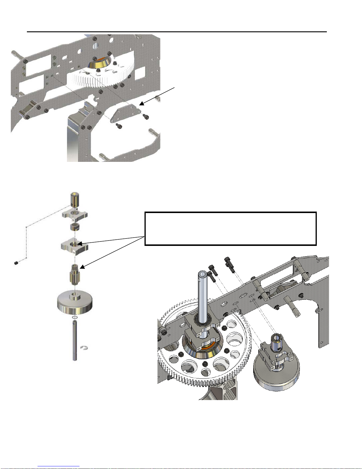
Install the constant drive gear onto the constant drive gear hub.
Slide the main sleeve into the one-way sprag clutch with the key
coinciding with the key slots and then slide the constant gear hub
into the protruding main sleeve bottom.
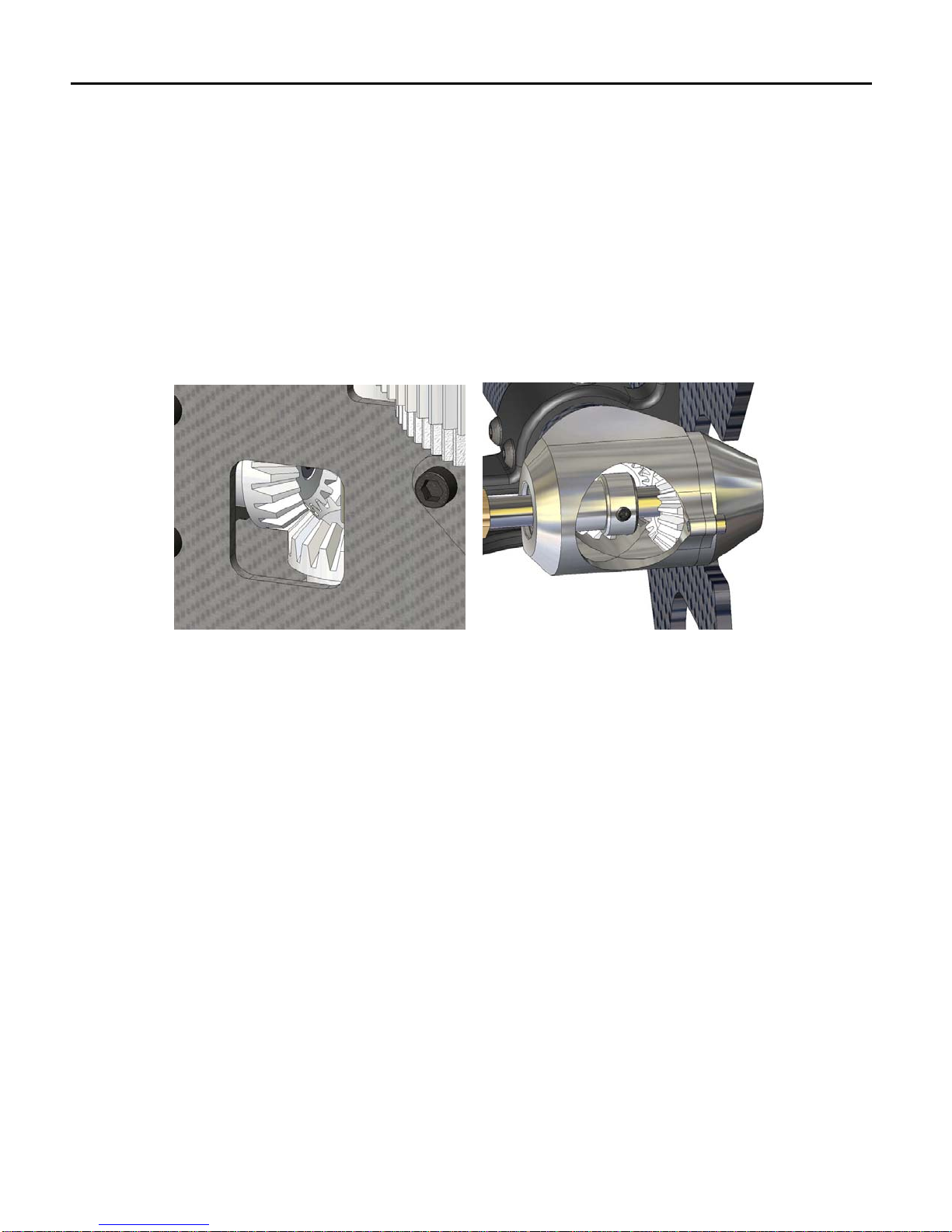
Slide the Main Shaft into the main gear
assembly and install the hardened pin
that locks the constant drive hub into the
main shaft and screw the M6x10
setscrew into the bottom of the main
shaft to secure the pin in place, There is
no need to over tighten this setscrew.
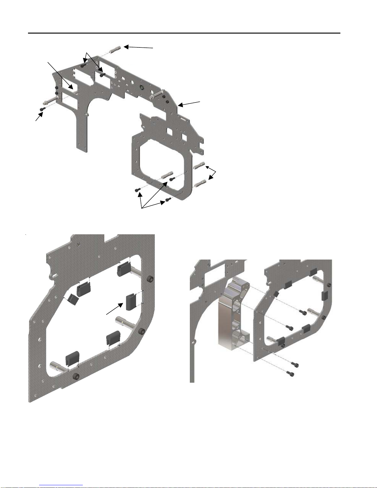
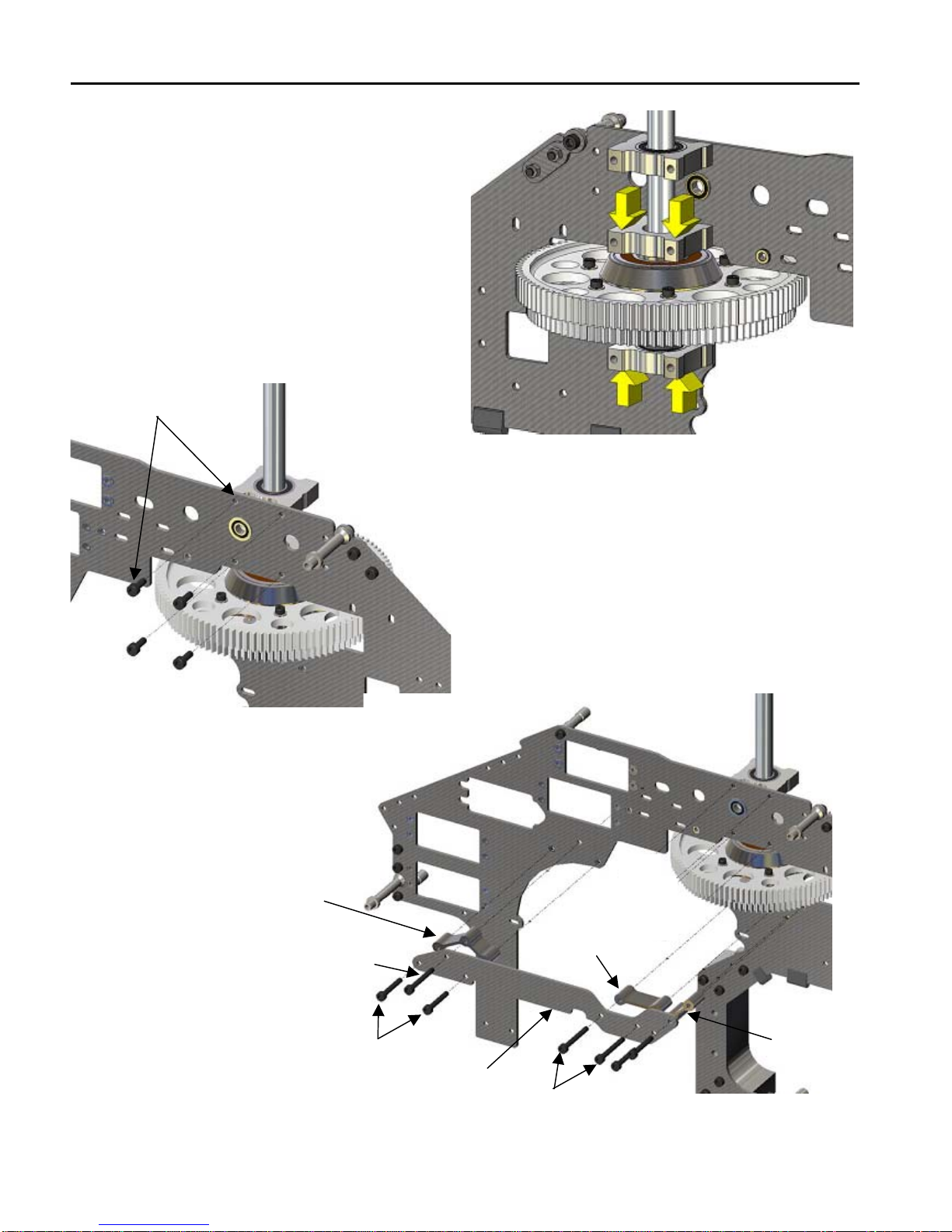
Slide the top bearing blocks and the
bottom bearing block oriented as
indicated by the small notched facing the
back. Notice that the small notches for
the entire bearing block should be facing
the rear side of the heli.
AV00-200-676 (Sharp edge should point toward the sleeve)
AV00-200-671
AV00-200-680
AV00-100-613
Open bearing side
faces up
Open bearing side
faces down
Open bearing side
faces up
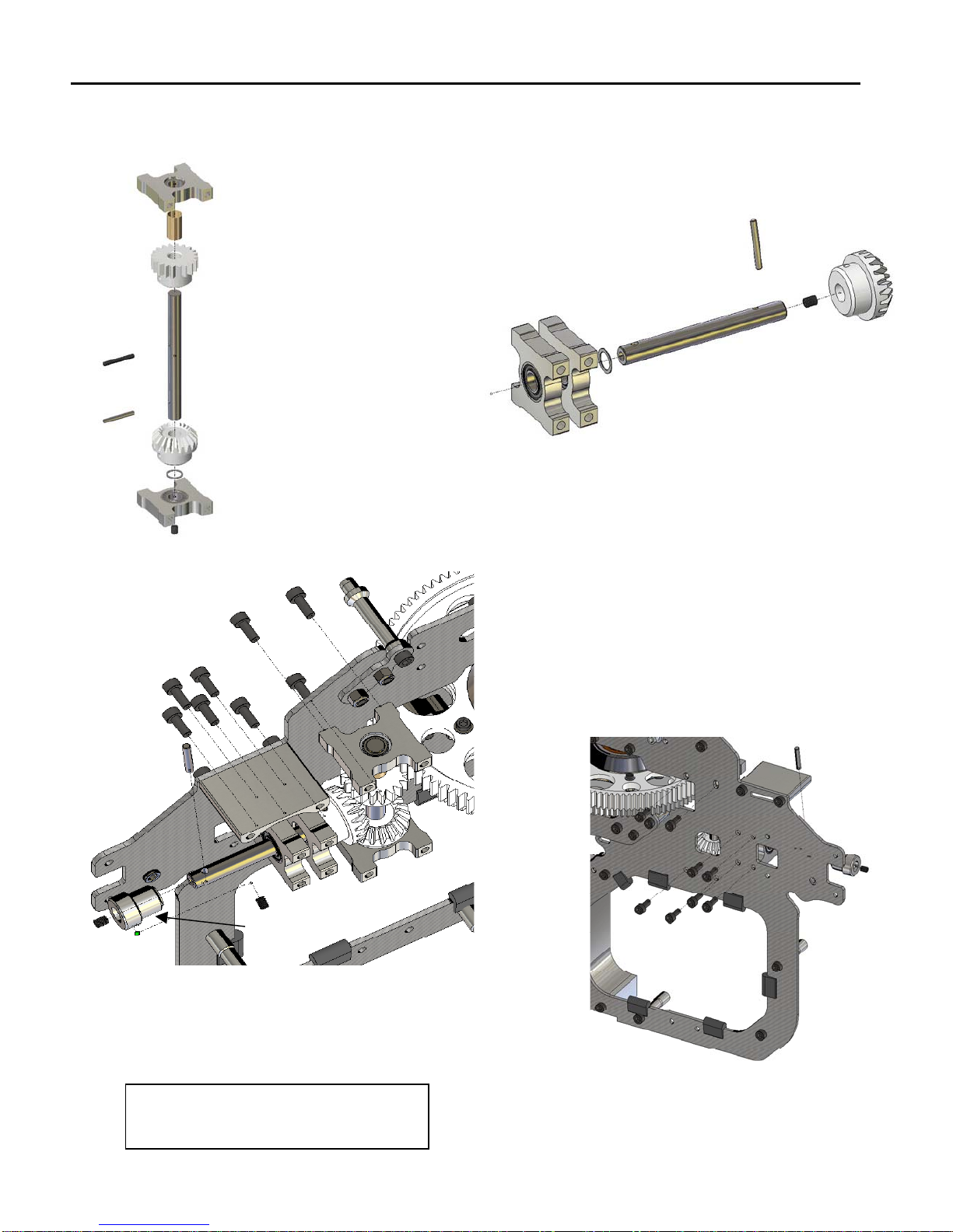
Small notch faces
back M6x10mm AV00-100-355 Main
shaft pin retainer setscrew
Small notch faces
back AV00-100-613
AV00-100-333
Main shaft pin
IMPORTANT NOTE: Use
Blue Loctite on the mainshaft
pin itself.This will prevent it
from sliding out even if the
setscrew becomes lose.
IMPORTANT NOTE: Pay attention to
the orientation of the bearing blocks.
The top block open bearing side should face
up, the mid one should face down and the
bottom one should face up.
Note: Unless indicated otherwise all screws, balls and threads are installed with Blue Loctite