2AVANT Aurora Ultimate 90 Assembly Manual
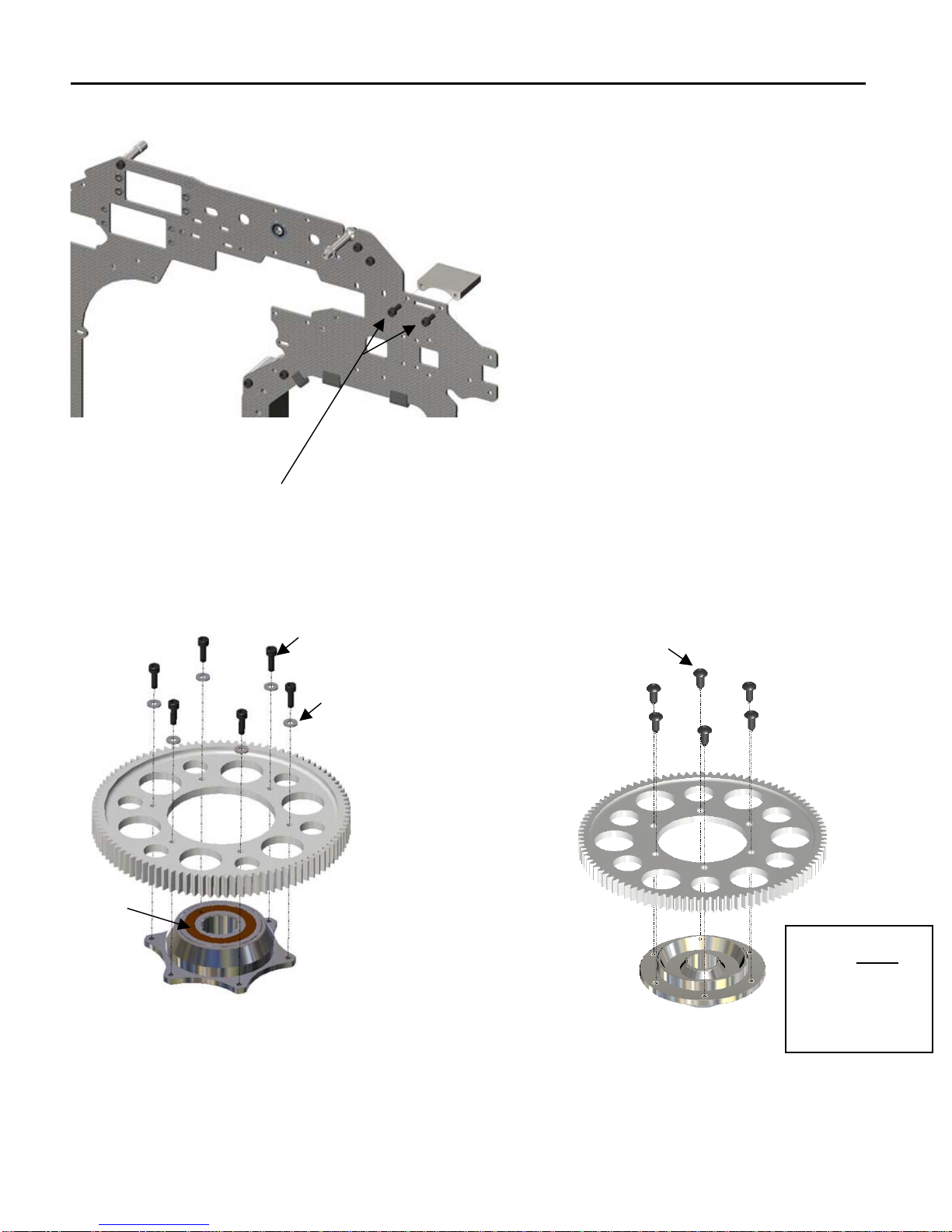
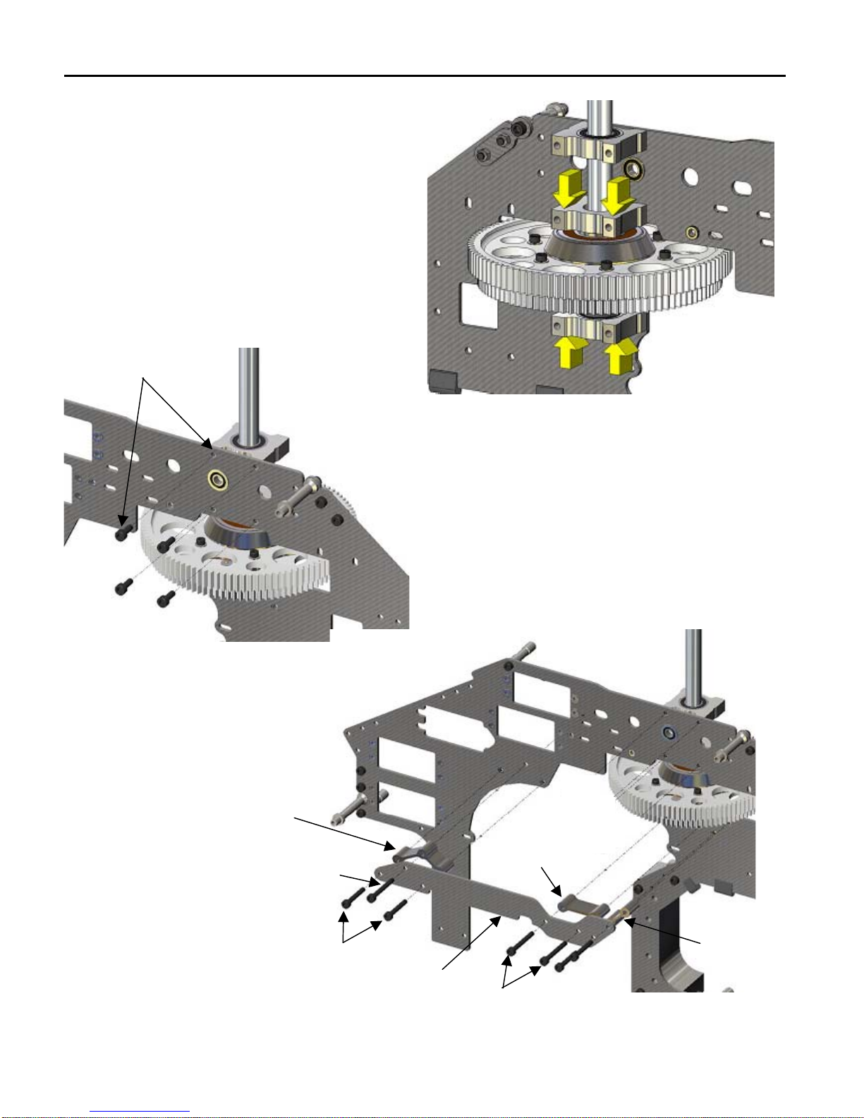
Note: Unless indicated otherwise all screws, balls and threads are installed with Blue Loctite
AVANT Aurora Ultimate 90
Assembly Manual V2.00
LIABILITY DISCLAIMER
This kit is for a radio controlled (RC) helicopter. RC Helicopters are not
toys. Moving parts can present a hazard to operators, bystanders and
anyone or anything that could be reached by the RC helicopter. Improper
operation, maintenance or assembly can potentially cause a helicopter to
pose a danger to persons or objects including but not limited to the
possibility of causing serious physical injury and even death. This product
is intended to be used by experienced adult radio control helicopter pilots
under controlled safety conditions and on locations properly authorized
and setup for safe flying and away from other people. Under no
circumstance should a minor be allowed to operate this or any radio
controlled helicopter without the approval, supervision and direction of his
parent or legal guardian who takes full responsibility for the minor's
actions. Do not operate an RC helicopter within the vicinity of homes,
trees, electrical lines during inclement weather or rain or near crowds of
people. After leaving its facilities the manufacturer has no way of
maintaining control or supervision over the assembly and/or operation of
the helicopter.
The manufacturer and/or its agents assume no responsibility or liability
whatsoever for any damages including but not limited to ones generated
by incidental or consequential damages.
The operator of the helicopter assumes all responsibility and liability that
could be result from the correct or incorrect operation of the helicopter.
Symbols:
Important, Correct, Incorrect, Danger, Allow it to set for some time before
continuing