Avantgarde duo xd series User manual

BEDIENUNGSANLEITUNG USER MANUAL
SERIES
DUO

INHALTSVERZEICHNIS TABLE OF CONTENT
SAFETY INFORMATION
PRECAUTIONS 4
PRECAUTIONS ON INSTALLATION 5
OPERATING VOLTAGE 5
SYSTEM UNPACKING
CONTENT OF PACKAGES 6
UNPACKING 7
SPEAKER ASSEMBLY 7
UNPACKING THE HORNS 8
ATTACHING HORNS AND PANELS 9
SYSTEM INSTALLATION
GENERAL SAFETY PRECAUTIONS 11
STANDARD CONNECTION 11
BI–WIRING CONNECTION 11
EARTHING OF METAL PARTS 13
OPERATION
GENERAL INFORMATION 15
SUBWOOFER INPUTS 15
INPUT SWITCH 15
POWER SWITCH 16
REMOTE ON/OFF 16
BALANCED XLR OUTPUT 17
LED BRIGHTNESS CONTROL 17
INPUTS FOR PROGRAMMING 17
SET EQ AND FILTERS 18 - 19
SAVE & LOAD FILTERS 19
SYSTEM SET UP TIPS
GENERAL TIPS 20
ROOM PLACEMENT AND TOE IN 20
INCLINATION OF SYSTEM 21
SPIKE PROTECTION STYROFOAM 22
FINE–TUNING THE SUB SETTINGS 23
SUBSONIC FILTER 23
FINE–TUNING BY TOE–IN OF SPEAKER 24
BURN–IN TIME 24
CHOOSING CABLES 24
CLEANING
CLEANING OF HIGH GLOSS SURFACES 25
CLEANING OF SATIN FINISHED SURFACES 25
CLEANING OF METAL SURFACES 25
WARRANTY TERMS 26 - 27
ADDRESS 28
SICHERHEITS INFORMATIONEN
SICHERHEITSHINWEISE
INSTALLATIONSHINWEISE
NETZSPANNUNG
SYSTEM AUSPACKEN
LIEFERUMFANG
AUSPACKEN
MONTAGE DER LAUTSPRECHERSYSTEME
AUSPACKEN DER HÖRNER
MONTAGE DER HÖRNER UND PANEELE
SYSTEM INSTALLATION
ALLGEMEINE SICHERHEITSHINWEISE
STANDARD VERKABELUNG
BI–WIRING VERKABELUNG
ERDUNG DER METALLTEILE
BEDIENUNG
ALLGEMEINE INFORMATIONEN
SUBWOOFER EINGANG
EINGANGSSCHALTER
EIN/AUS–SCHALTER
FERNEINSCHALTUNG
SYMMETRISCHER XLR AUSGANG
LED HELLIGKEITREGLER
EINGÄNGE ZUM PROGRAMMIEREN
EQ UND FILTER EINSTELLEN
FILTER SPEICHERN & LADEN
SYSTEM AUFBAU TIPPS
ALLGEMEINE TIPPS
PLATZIERUNG UND ANWINKELN DES SYSTEMS
NEIGUNG DES SYSTEMS
SPIKE SCHUTZVERPACKUNG
FINE–TUNING DER SUB EINSTELLUNGEN
SUBSONIC FILTER
FINE–TUNING DURCH ANWINKELN
EINSPIELZEIT
WAHL DER KABEL
REINIGUNG
REINIGUNG DER HOCHGLANZ OBERFLÄCHEN
REINIGUNG DER SEIDENMATT OBERFLÄCHEN
REINIGUNG DER METALL OBERFLÄCHEN
GARANTIE BESTIMMUNGEN
ADRESSE

SICHERHEIT SAFETY
• Um Feuer und die Gefahr eines elektri-
schen Schlages zu vermeiden, dürfen die
Geräte weder Regen noch Feuchtigkeit aus-
gesetzt werden.
• Betriebsbedingungen:
Raumtemperatur 5 - 35 0C
Luftfeuchtigkeit 10 - 75%
• Um einen elektrischen Schlag zu vermei-
den, die Gehäuse niemals öffnen. Wartungs-
arbeiten stets und ausschließlich vom auto-
risierten Fachpersonal ausführen lassen.
• Hohe Abhörlautstärken beeinträchtigen
das Hörvermögen und können zu bleiben-
den Gesundheitsschäden führen. Das Laut-
sprechersystem nicht zu laut stellen!
• Sollte ein fester Gegenstand oder Flüs-
sigkeit in das Innere der Komponenten
gelangen, alle Geräte ausschalten und die
Komponenten vom autorisierten Fachperso-
nal überprüfen lassen, bevor Sie sie weiter
benutzen.
• Bei längerer Nichtbenutzung des HiFi–
Systems oder bei Gewittergefahr alle Geräte
von Stromnetz und Antennen trennen. Zum
Abtrennen die Netzkabel stets am Stecker
und niemals am Kabel selbst anfassen. Den
Stecker nie mit nassen Händen berühren.
• Die Geräte nur vom autorisierten Fachper-
sonal reparieren und installieren lassen.
• Diese Lautsprecher sind für die Wiederga-
be von Tonsignalen bestimmt.Jede andere
Verwendung, insbesondere der gewerbliche
Betrieb, ist ausdrücklich ausgeschlossen.
VORSICHT
5 0C
35 0C
10%
75%
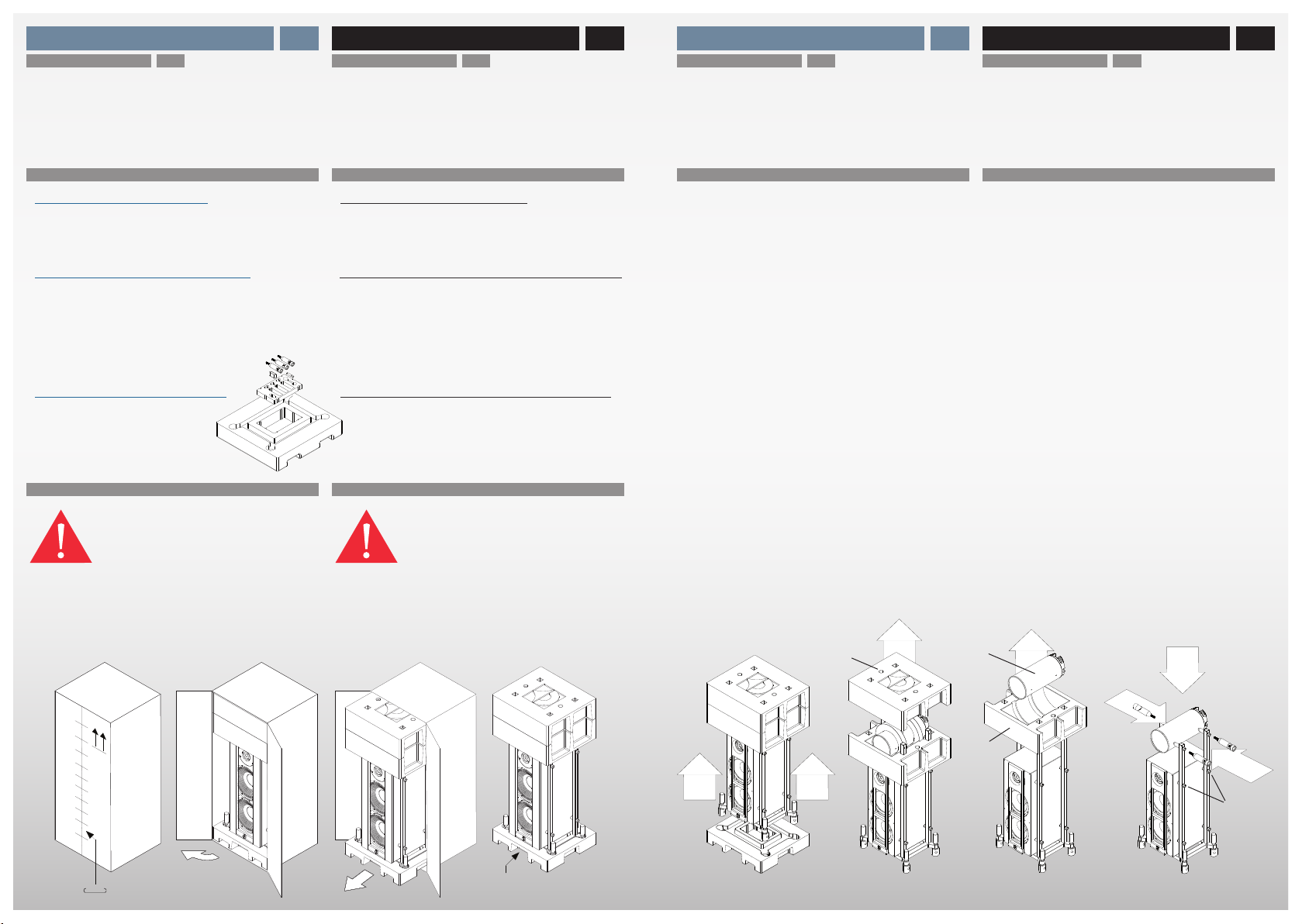
• Lautsprecher nicht am Horn tragen. Beim
Tragen immer nur an den Gehäusestangen
halten.
• Die Lautsprecher auf eine ebene, solide
Unterlage stellen.
• Gute Luftzirkulation ist wichtig, um ei-
nen internen Hitzestau zu vermeiden.
Die Lautsprecher an einem gut belüfte-
ten Ort betreiben. Das System nicht in
die Nähe von Wärmequellen (z.B. Öfen,
Warmluftauslässe) stellen und nicht direkter
Sonnenbestrahlung, Staub oder mechani-
scher Vibration aussetzen.
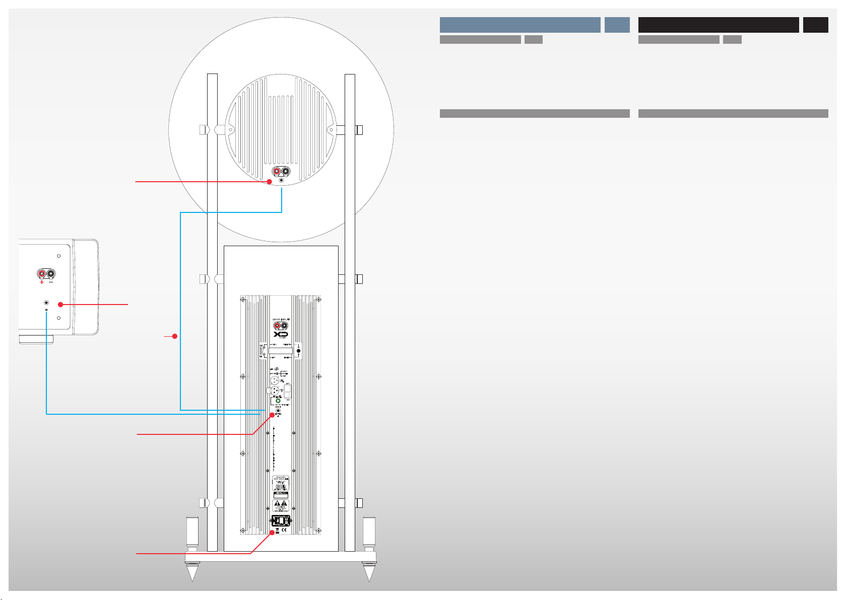
• Alle elektrischen Verbindungen fest und
sicher anschließen. Die Stecker fest in die
Buchsen einstecken. Lockere Anschlüsse
können Brummen/Rauschen verursachen
und die Geräte beschädigen. Um sichere
Verbindungen zu gewährleisten, nur hoch-
wertige Stecker verwenden.
• Um eine Beschädigung der Oberflächen zu
vermeiden, niemals Alkohol, Farbverdünner
oder Chemikalien verwenden.
• Diese Installations- und Bedienungs-
anleitung sorgfältig lesen, bevor das Laut-
sprechersystem in Betrieb genommen wird.
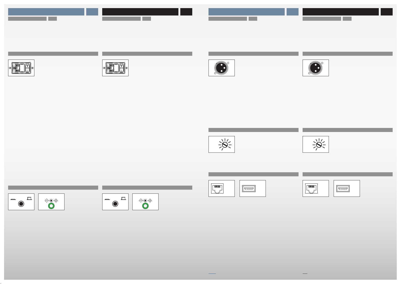
Vergewissern Sie sich vor der
Inbetriebnahme der Komponenten, dass die
Geräte der örtlichen Netzspannung entspre-
chen:
Europa 230 V AC, 50 Hz
England 240 V AC, 50 Hz
USA, Kanada 120 V AC, 60 Hz
Andere Länder 100, 120, 220 oder
240 V AC, 50/60 Hz
INSTALLATIONSHINWEISE
NETZSPANNUNGEN
PRIVATE USE ONLY
• It is intended to alert the user of the pres-
ence of uninsulated “dangerous voltage“
within the products enclosure that may be
of sufficient magnitude to constitute a risk of
electrical shock to persons.
• Conditions for operation:
room temperatur 5 - 35 0C
humidity 10 - 75%
• To prevent fire, shock or damage, do not
expose the components to rain or moisture.
To avoid electrical shock, do not open the
cabinet of the components. Refer servicing
to qualified personnel only.
• Excessive sound pressure levels might
cause serious damage to your health. Do
not operate the speaker system at excessive
levels for a long period of time.
• Should any solid object or liquid fall into
the cabinet of the components, unplug the
unit and have it checked by qualified person-
nel before operating it any further.
• Unplug the components of your system
from the wall outlet and antenna if they are
not to be used for an extended period of
time. To disconnect the power cord, pull it
out by the plug. Do not pull the cord itself.
Never touch the plugs with wet hands.
• Only let qualified personnel repair or reas-
semble the components of the system.
• These loudspeakers are designed for the
playback of audio signals. Any other use,
especially in commercial applications, is ex-
pressly prohibited.
CAUTION
! SERVICE !
SICHERHEIT SAFETY
• Do not move or carry the speakers by
holding the horn assembly.
• Place the components of the system on a
flat solid surface.
• Good air circulation is essential to prevent
internal heat build-up in the components.
Place units in a location with sufficient air
circulation. Do not install the speakers in a
location near heat sources such as radia-
tors, or in a place subject to direct sunlight,
excessive dust, or mechanical vibration.
• Connect everything securely. Always in-
sert the plugs fully into the jacks. A loose
connection may cause hum pickup and can
damage the system. To prevent malfunc-
tion and short circuits, use only high quality
cables with self tightening banana speaker
and RCA or XLR plugs.
• To avoid damaging the finish, never use
alcohol, paint thinner or chemicals to clean
the components.
• Read this operators manual thoroughly be-
fore operating the speaker system.
Before connecting the speaker system to
the power source, check that the operating
voltage of the unit is the same as the local
power line voltage.
Europe 230 V AC, 50 Hz
United Kingdom 240 V AC, 50 Hz
USA, Canada 120 V AC, 60 Hz
Other countries 100, 120, 220 or
240 V AC, 50/60 Hz
PRECAUTIONS ON INSTALLATION
OPERATING VOLTAGE
54

SYSTEM INSTALLATION SYSTEM INSTALLATION
AUSPACKEN DES LAUTSPRECHERSYSTEMS UNPACKING THE SPEAKER SYSTEM
Beim Auspacken und Aufstellen das hohe
Gewicht der Lautsprecher beachten! Für
diese Arbeiten empfehlen wir dringend die
Zuhilfenahme einer zweiten Person!
LIEFERUMFANG CONTENT OF PACKAGES
• Die Verpackung des Lautsprechers:
2 x Papp-Kartonage mit dem Lautsprecher
2 x Papp-Kartonage mit den Hörnern
1 x Papp-Kartonage mit den Front-Paneelen
• Die Zubehörbox im Styrodurschutz (rechts):
1 x Öl (für Gummidichtung von Mitteltonhorn)
1 x Schwamm (zum Auftragen des Öls)
2 x Montageschraube (flach)
1 x Montageschraube (rund)
2 x Abstandshalter (flach)
1 x Abstandshalter (rund)
• Die Kabelbox im Styrodurschutz (links):
1 x Kabelbrücken
1 x Erdungskabel
1 x Netzkabel
1 x Ersatzsicherungen
• The packing of the system consists of:
2 x boxes with the speaker body
2 x boxes with the horns
1 x box with the front panels
• The accessory box (in bottom left styrofoam box) contains:
1 x lubricating oil (for midrange rubber seal)
1 x sponge (to apply lubrication oil)
2 x mounting screws (plane)
1 x mounting screws (rounded)
2 x spacers (plane)
1 x spacers (rounded)
• The cable box (in bottom right styrofoam box) contains:
1 x Jumper cable
1 x Earthing cable
1 x Power cable
1 x Replacement fuses
① Klammern entfernen
② Kartonage öffnen
③ Lautsprecher vorsichtig nach vorne herausziehen.
① Remove the clamps.
② Open the box.
③ Carefully pull out the speaker to the front.
Please note the heavy weight of the speaker
system when unpacking and installing the
system. We strongly advise doing this work
only with the help of a second person!
MONTAGE DES LAUTSPRECHERSYSTEMS SPEAKER ASSEMBLY
④ Lift speaker from the bottom styrofoam box.
Lift the upper styrofoam box of midrange cylinder
before, to reduce the overall weight when carying the
speaker system.
See step ⑤– ⑧
⑤ Lift upper styrofoam box of midrange cylinder.
⑥ Remove midrange cylinder
⑧ Lift bottom styrofoam box of midrange cylinder
⑨ Mount the midrange cylinder to the rails by:
⑨ a) loosen the upper screws of the subwoofer to get
more clearance between the frame rails of the
speaker stand.
⑨ b) mount the midrange tube (open side facing to the
front) with the spacers and mounting screws to the
frame.
⑨ c) retighten the upper screws of the subwoofer.
④System aus der unteren Styrodur Verpackung heben.
Um das Gewicht beim Herausheben des Lautsprechers
zu verringern, kann die obere Styrodur–Verpackung
des Mitteltöners auch vorab abgehoben werden.
Siehe Schritt ⑤– ⑧
⑤Obere Styrodur–Verpackung des Mitteltöners abheben.
⑥ Mittelton–Zylinder herausheben.
⑧ Untere Styrodur–Verpackung des Mitteltöners abheben.
⑨Mittelton–Zylinder an das Gestell anschrauben.
⑨a) obere Montageschrauben am Subwoofer etwas
lockern, um die lichte Weite zwischen den Gestell-
stangen zu vergrößern.
⑨b) Mittelton–Zylinder (mit dem offenen Ende nach vorne
zeigend) mit den beiliegenden Montageschrauben an
das Gestell anschrauben.
⑨c) obere Montageschrauben am Subwoofer anziehen.
SYSTEM INSTALLATION SYSTEM INSTALLATION
Zubehör– bzw. Kabelbox
Accessory box or cable box
④① ②
⑥
⑧
⑨a
⑨b
⑤
76

AUSPACKEN DER HÖRNER UNPACKING THE HORNS
⑩ Open the packing box of the midrange horn.
⑪ Unscrew the midrange horn from the threaded trans-
port fixture by turning it counter–clockwise.
⑫ Open the inner packing box of the tweeter horn.
⑬ Unscrew the tweeter horn from the threaded transport
fixture by turning it counter–clockwise.
⑩Kartonage des Mitteltonhorns öffnen.
⑪ Mitteltonhorn aus der Transportfixierung entgegen dem
Uhrzeigersinn herausschrauben.
⑫Innenliegende Kartonage des Hochtonhorns öffnen.
⑬ Hochtonhorn aus der Transportfixierung entgegen dem
Uhrzeigersinn herausschrauben.
SYSTEM INSTALLATION SYSTEM INSTALLATION
MONTAGE DER HÖRNER ATTACHING THE HORNS
⑭ By using the small sponge, apply the lubricating oil to
the inner side and front edge of the rubber ring on the
front of the midrange cylinder.
⑮ Screw the midrange horn into the midrange cylinder by
slowly turning it clockwise until the horn obtains a tight
fit. A good handtight force will suffice, there is no need
to use excessive force!
⑯ Remove the styrofoam rings which protect the edges of
the midrange horns.
⑰ Screw the tweeter horn into thread at the frontside of
the subwoofer by slowly turning it clockwise until the
horn obtains a tight fit. A good handtight force will suf-
fice, there is no need to use excessive force!
SYSTEM INSTALLATION SYSTEM INSTALLATION
⑭Mit dem kleinen Schwamm etwas Öl als Gleitmittel auf
die Gummidichtung an der Vorderkante des Mittelton–
Zylinders auftragen.
⑮ Das Mitteltonhorn vorsichtig im Uhrzeigersinn in das
Innengewinde des Mittelton–Zylinders einschrauben.
Auf richtig festen Sitz achten. Dabei jedoch keine über-
mäßige „Gewalt“ ausüben.
⑯ Die an der Kante des Mitteltonhorns umlaufenden
Schaumstoffringe entfernen.
⑰ Das Hochtonhorn vorsichtig im Uhrzeigersinn in das
Innengewinde auf der Frontseite des Subwoofers ein-
schrauben. Auf richtig festen Sitz achten. Dabei jedoch
keine übermäßige „Gewalt“ ausüben.
MONTAGE DER PANEELE ATTACHING THE PANELS
⑱ Unpack the panels. Each panel is labelled on its back-
side indicating its position on the left or the right side of
the subwoofer respectively.
⑲ Carefully attach the panels to the holes on the left and
right side of the subwoofer cabinet front.
⑱Die Paneele auspacken. Auf der Rückseite der Paneele
befindet sich ein Etikett mit der jeweiligen Positionsan-
gabe (linke oder rechte Seite).
⑲ Die Paneele vorsichtig in die Löcher auf der linken oder
rechten Vorderseite des Subwoofers aufstecken.
⑩ ⑪ ⑫ ⑬
⑭
⑮
⑯
⑰ ⑲
98

SYSTEM INSTALLATION SYSTEM INSTALLATION
ALLGEMEINE SICHERHEITSHINWEISE GENERAL SAFETY PRECAUTIONS
• Vor der Verkabelung der Lautsprecher müssen alle Geräte
ausgeschaltet bzw. vom Stromnetz getrennt sein. Sicher-
heitshalber den Netzstecker ziehen.
• Die Geräte niemals mit offenen Eingängen (unverkabelt)
betreiben! Um Defekte zu vermeiden, müssen alle Geräte
vor dem Netzanschluss ordnungsgemäß verkabelt sein!
• Beim Anschluss per Lautsprecherkabel auf richtige Pola-
rität achten! Verpolung kann den Klang beeinträchtigen und
die Endstufen bzw. den Lautsprecher beschädigen! Die +/–
Adern niemals kurzschließen!
Hochwertiges Lautsprecherkabel und solide Bananen-
stecker oder Kabelschuhe verwenden.
• The power to all components must be switched “off” (or
disconnected from the household AC) before making any
audio connections.
• To prevent malfunction or defects, do not operate compo-
nents with open input/output terminals. Before making any
AC power connections, all components have to be properly
installed and connected.
• Control the polarity! Do not mix up + and –. Wrong polar-
ity may deteriorate sound quality, damage the amplifier and
active power module of the subwoofer. Do not short circuit
the +/– electric poles of the speaker cables.
Use high quality cable with solid speaker plugs (spades,
bananas etc).
STANDARD VERKABELUNG STANDARD CONNECTION
① Den Mittelton–Eingang ❶ und den kombinierten Sub-
woofer/Hochton–Eingang ❷ mit der Kabelbrücke ❸–MID
verbinden. Die Kabelbrücke finden Sie in der Zubehörbox.
② Den Lautsprecher–Ausgang ❹ des Vollverstärkers bzw.
der Endstufe mit dem Mittelton–Eingang ❶ des Lautspre-
chersystems verbinden.
③ Erst jetzt den Subwoofer mit dem beigepackten Netzka-
bel an das Stromnetz anschließen und einschalten.
① Connect the Midrange–Input ❶ and the combined Sub-
woofer/Tweeter–Input ❷ with the jumper cable ❸–MID.
The jumper cable is included in the accessory box.
② Connect the Speaker–Output ❹ of your power (or inte-
grated) amplifier with the Midrange–Input ❶ of the speaker
system.
③ Only now, connect the AC power cords of the compo-
nents to a household AC outlet and turn on the subwoofer.
BI–WIRING VERKABELUNG BI–WIRING CONNECTION
① Den Lautsprecher–Ausgang ❹ des Vollverstärkers bzw.
der Endstufe mit dem Mittelton–Eingang ❶ des Lautspre-
chersystems verbinden.
② Den Lautsprecher–Ausgang ❹ des Vollverstärkers bzw.
der Endstufe mit dem kombinierten Subwoofer/Hochton–
Eingang ❷ des Lautsprechersystems verbinden. Die Ver-
bindung zwischen Mittelton–Eingang ❶ und Subwoofer/
Hochton–Eingang ❷ entfällt oder muss entfernt werden.
③ Erst jetzt den Subwoofer mit dem beigepackten Netzka-
bel an das Stromnetz anschließen und einschalten.
① Connect the Speaker–Output ❹ of your power (or inte-
grated) amplifier with the Midrange–Input ❶ of the speaker
system.
② Connect the Speaker–Output ❹ of your power (or in-
tegrated) amplifier with the combined Subwoofer/Tweet-
er–Input ❷ of the speaker system. There is no connec-
tion between the Midrange–Input ❶ and the Subwoofer/
Tweeter–Input ❷.
③ Only now, connect the AC power cords of the compo-
nents to a household AC outlet and turn on the subwoofer.
EARTH
GND
LINE INPUT LINE OUTPUT
12V DC
USB
OK
MENU
ENTER
SLICE
SPKR INPUT
MANUFACTURED IN GERMANY BY AVANTGARDE ACOUSTIC
LED LS/0/XLR
AES/EBU
MENU
ESC
SIG
CLIP SELECT
ENTER
LED
XLR
SPKR
MUTE
XLR
OUT
XLR
IN
12V DC TRIGGER
LAN
USB
EARTH
ON OFF
CAUTION!
Do not open.
Risk of
electrical shock!
MANUFACTURED IN GERMANY BY AVANTGARDE ACOUSTIC
SPKR INPUT
XD-1000
AMP MODULE
SERIAL NO.
MAX. POWER
CONSUMPTION
1.200 WATTS
FUSE 6,3 A SLOW
INPUT
100-240 VAC
50-60HZ
❶
❹
❷
❸
1110
–MID

SYSTEM INSTALLATION SYSTEM INSTALLATION
ERDUNG DER METALLTEILE EARTHING OF METAL PARTS
• Zur Verbesserung der Klangqualität und/oder zur Vermei-
dung von Störgeräuschen sind die Lautsprechersysteme
mit Erdungsbuchsen ausgerüstet.
• Am Gussdeckel des Mitteltontreibers und an der Sub-
wooferendstufe befinden sich Erdungsbuchsen ❺ und ❻.
• Die Erdungsbuchse der Endstufe ❻ ist mit dem Masse-
leiter der Netz–Kaltgerätebuchse ❼ verbunden.
① Die Erdungsbuchse des Mitteltöners ❺ mit dem beilie-
genden Kabel ❸–EARTH mit der Erdungsbuchse der Sub-
woofer–Endstufe ❻ verbinden. Das Erdungskabel befindet
sich in der Zubehörbox.
Sobald die Netz–Kaltgerätebuchse des Lautsprechersys-
tems ❼ an einem 3–poligen und damit geerdeten Netzan-
schluss betrieben wird, sind die Metallteile geerdet.
② Wenn der Subwoofer an einem 2–poligen und damit
ungeerdeten Netzanschluss betrieben wird, oder um die
Klangqualität unter Umständen zu verbessern, empfehlen
wir zusätzlich auch die Erdungsbuchse des Vollverstärkers
oder der Vorstufe ❽ (falls vorhanden) mit der Erdungs-
buchse der Subwoofer–Endstufe ❻ zu verbinden.
Das hierfür benötigte Erdungskabel ist nicht im Lieferum-
fang enthalten. Beliebige 1–polige Kabel mit einem Leiter-
querschnitt von >0,5 qmm (z.Bsp. AWG 20) verwenden.
• To further improve sound quality and/or to counteract
noise and hum issues the speakers feature 2mm earthing
sockets.
• The rear cover of the midrange driver and the subwoofer
amplifier feature earthing sockets ❺ and ❻.
• The earthing socket ❻ is connected to the earthing pin of
the subwoofer mains input socket ❼.
① Connect the earthing socket of the midrange ❺ with the
earthing socket of the subwoofer amplifier ❻ by using the
earthing cable ❸–EARTH. The earthing cable is included in
the accessory box.
As soon as the subwoofer mains ❼ is connected to an
earthed 3–pin mains outlet, the earthing sockets are con-
nected to the earth of your household power line.
② If the subwoofer mains is connected to a 2–pin un-
earthed mains outlet or to possibly further improve the
sound quality it is recommended to as well connect the
earthing socket of the integrated– or pre–amplifier ❽ (if
available) to the earthing socket of the subwoofer amplifier
❻ of the speaker system.
The required earthing cable for this connection is not in-
cluded with your speaker system. You can use any single–
pole cable of >0.5 square mm (ex. AWG 20).
EARTH
GND
LINE INPUT LINE OUTPUT
12V DC
USB
OK
MENU
ENTER
SLICE
SPKR INPUT
MANUFACTURED IN GERMANY BY AVANTGARDE ACOUSTIC
LED LS/0/XLR
AES/EBU
MENU
ESC
SIG
CLIP SELECT
ENTER
LED
XLR
SPKR
MUTE
XLR
OUT
XLR
IN
12V DC TRIGGER
LAN
USB
EARTH
ON OFF
CAUTION!
Do not open.
Risk of
electrical shock!
MANUFACTURED IN GERMANY BY AVANTGARDE ACOUSTIC
SPKR INPUT
XD-1000
AMP MODULE
SERIAL NO.
MAX. POWER
CONSUMPTION
1.200 WATTS
FUSE 6,3 A SLOW
INPUT
100-240 VAC
50-60HZ
❺
❽
❸
❻
❼
1312
–EARTH

BEDIENUNG OPERATION
ALLGEMEINE INFORMATIONEN GENERAL INFORMATION
• Die Subwoofer sind im Eingang mit einem hochwertigen
Audioübertrager ausgerüstet. Dieser ermöglicht einen voll-
kommen masselosen Anschluss des Subwoofersystems
und sichert damit größtmögliche Störsicherheit.
• Beachten Sie, dass Hornsysteme einen – im Vergleich
zu “konventionellen” Lautsprechern – höheren Wirkungs-
grad haben. Schlechte Rausch- und Geräuschspannungs-
abstände der verwendeten Komponenten (z.B. Endstufen
etc.) werden dementsprechend lauter wiedergegeben und
können somit unter Umständen hörbar sein. Gegebenen-
falls den Fachhändler kontaktieren und die Komponenten
überprüfen lassen.
• The subwoofer has a special high performance audio
transformer in the input stage to allow for a ground free
connection of the subwoofer. This will eliminate any ground
loops and hum & noise problems in your installation.
• Note, that the horn systems are extremely sensitive
compared to “conventional” speaker systems and
consequently not only music but also hum noises caused
by low signal-to-noise ratios of the used electronic
components (ex. amplifiers) are reproduced louder and
might become audible. Contact your dealer and have your
audio electronics checked.
SUBWOOFER EINGANG SUBWOOFER INPUTS
• Zusätzlich zu den empfohlenen Lautsprecherbuchsen ❷
sind die Subwoofer auch mit einer XLR–Eingangsbuchse ⓰
(weiblich) ausgestattet. Damit können die Subwoofer wahl-
weise auch mit symmetrischen (oder unsymmetrischen)
Line-Signalen aus Vorstufenausgängen versorgt werden.
• Für den unsymmetrischen Anschluss mit RCA Cinchka-
beln werden Adapter benötigt. Hierbei muss RCA–Signal
mit PIN 2, RCA–Masse mit PIN 1 und wahlweise PIN 1 mit
PIN 3 verbunden sein.
Zum Aktivieren des entsprechenden Eingangs siehe den
folgenden Abschnitt Eingangsschalter ⓮.
• In addition to the recommended speaker input terminals
❷ the subwoofer has a XLR–input-terminal ⓰ (female).
This way the subwoofer can be easily driven by symmetri-
cal and asymmetrical line level signals of preamplifiers.
• An RCA/XLR adaptor is required for connection via
RCA cables, which connects RCA–signal to PIN 2 and
RCA–ground to PIN 1. Optionally it is possible to bridge
PIN 1 with PIN 3.
Please see the following chapter Input–Switch ⓮ to acti-
vate the respective input.
2
1
3
LINE INPUT LINE OUTPUT
12V DC
USB
OK
MENU
ENTER
SLICE
SPKR INPUT
MANUFACTURED IN GERMANY BY AVANTGARDE ACOUSTIC
LED LS/0/XLR
AES/EBU
MENU
ESC
SIG
CLIP SELECT
ENTER
LED
XLR
SPKR
MUTE
XLR
OUT
XLR
IN
12V DC TRIGGER
LAN
USB
EARTH
ON OFF
CAUTION!
Do not open.
Risk of
electrical shock!
MANUFACTURED IN GERMANY BY AVANTGARDE ACOUSTIC
SPKR INPUT
XD-1000
AMP MODULE
SERIAL NO.
MAX. POWER
CONSUMPTION
1.200 WATTS
FUSE 6,3 A SLOW
INPUT
100-240 VAC
50-60HZ
EINGANGSSCHALTER INPUT SWITCH
• Beide Eingänge ❷ und ⓰ können parallel angeschlossen
werden. Mit dem Eingangschalter ⓮ kann zwischen den
beiden Eingängen umgeschaltet werden.
• Der Eingangschalter ⓮ hat eine Mittelstellung (MUTE), die
die Eingänge stumm schaltet und so evtl. eine Fehlersuche
(z.B. wenn ein Brumm auftritt) erleichtert.
• Both inputs ❷ and ⓰ can be connected in parallel. With
the Input–Switch ⓮ the respective input can be selected.
• The Input–Switch ⓮ also has a middle position (MUTE),
which mutes the inputs. This can be helpful during trouble-
shooting (e.g. when hum occurs).
2
1
3
SPKR
MUTE
XLR
SPKR
MUTE
XLR
1514
❷
❾
❿
⓫
⓮
⓭
⓯
❼
⓬
⓱
⓰
⓴
⓳
❻
⓲

BEDIENUNG OPERATION BEDIENUNG OPERATION
EIN/AUS–SCHALTER POWER SWITCH
FERNEINSCHALTUNG REMOTE ON/OFF
• Das beiliegende Netzkabel an der Kaltgerätebuchse ❼
anschließen. Alternativ können auch andere hochwertige
Netzkabel mit Kaltgerätestecker verwendet werden.
• Die XD-1000 Bassendstufe hat einen 2–stufigen Netz-
schalter ❼:
POSITION I = EIN
• Das Gerät ist permanent eingeschaltet. Der Subwoofer ist
für Dauerbetrieb ausgelegt und wegen klanglicher Vortei-
le empfehlen wir, ihn ständig eingeschaltet zu lassen. Der
Stromverbrauch im Leerlauf liegt bei ca. 10 Watt.
Der Betriebszustand wird durch die LED an der Vorder-
seite des Lautsprechers angezeigt.
POSITION 0 = AUS
• Die Stromversorgung des Lautsprechers ist ganz abge-
schaltet. Bei längerer Abwesenheit sollten die Systeme
ausgeschaltet und vom Netz getrennt werden. Unbedingt
auch die „Sicherheitshinweise“ in dieser Bedienungsanlei-
tung lesen.
• The supplied power cord can be connected to the Mains
Input–Socket ❼. Alternatively you may use any other high
quality power cord that features the appropriate IEC plug.
• The XD-1000 bass amplifier module has a 2–position
power switch ❼:
POSITION I = ON
• The speaker will be permanently “On”. The subwoofer has
been engineered for permanent use and due to sonic ad-
vantages we recommend to leave it always switched “On”.
Power consumption is about 10 Watts when not in use.
The operation is indicated by the LED at the frontside of
the speaker.
POSITION 0 = OFF
• The speaker is turned to permanent “OFF”. Turn the
system “Off”, if your system is not in use over a longer
period. Please carefully read the “Precaution and Safety”
instructions in this manual.
• Ist der Remote-Schalter ⓳ gedrückt auf der ON-Position
und der Netzschalter ❼ eingeschaltet, schaltet sich der
Subwoofer nur ein, wenn eine 12 Volt-Gleichspannung an
der „Ferneinschaltungs–Buchse“ ⓴ anliegt. Wird diese
12-V-Spannung abgeschaltet, schaltet sich der Subwoofer
automatisch ab.
Verwenden Sie ein 12V Schaltspannungskabel mit 3,5mm
Mono–Klinkenstecker um das Steuergerät (z.B. Surround-
oder Multiroomverstärker) mit der „Ferneinschaltungs–
Buchse“ ⓴ zu verbinden.
Der Schaltstrom beträgt circa 20 mA je Subwoofer.
• If the remote switch ⓳ is pressed into its ON-Position
and the power switch ❼ is switched ON, the subwoofer will
only operate when a 12V trigger voltage is detected at the
remote-trigger socket ⓴. The subwoofer will automatically
switch OFF, when the 12V trigger voltage is switched OFF.
Use a remote 12V trigger cable with 3,5mm mono phone
jacks to connect your electronics (surround receiver, multi-
room amplifier etc.) with the remote-trigger socket ⓴.
The switching current is approx. 20 mA per subwoofer.
SYMMETRISCHER XLR AUSGANG BALANCED XLR OUTPUT
1
2
3
PIN 2 HOT Signal (in phase)
PIN 3 COLD Signal (inverted)
PIN 1 GND Ground
PIN 2 HOT Signal (in Phase)
PIN 3 COLD Signal (invertiert)
PIN 1 GND Gerätemasse (Erde)
• Zum Anschluss weiterer Subwoofer dient ein Paar sym-
metrischer XLR–Ausgangsbuchsen (männlich) ⓯.
• Dieses Weiterschleifen des Signals funktioniert nur, wenn
die XLR–Eingangsbuchse ⓰ (weiblich) in Betrieb ist.
• Für den unsymmetrischen Anschluss mit RCA Cinchka-
beln werden Adapter benötigt. Hierbei muss RCA–Signal
mit PIN 2 und RCA–Masse mit PIN 1 verbunden sein.
• To connect additional subwoofers 1 x pair of balanced XLR
output sockets (male) ⓯ is provided.
• This routing of the signal is only functional, when the
XLR–input-terminal ⓰ (female) is beeing used.
• An RCA/XLR adaptor is required for connection via RCA
cables, which connects RCA–signal to PIN 2 and RCA–
ground to PIN 1.
1
2
3
LED HELLIGKEITSREGLER LED BRIGHTNESS CONTROL
• Den LED–Helligkeitsregler ⓭ drehen, um die Helligkeit
der frontseitigen LED-Betriebsanzeige zu verändern.
• Turn the LED Brightness–Attenuator ⓭ to dimm the
brightness of the LED on the frontside of the speaker.
EINGÄNGE ZUM PROGRAMMIEREN INPUTS FOR PROGRAMMING
• Neben den Bedienelementen mit Display am Gerät (❾,
⓫ und ⓬) kann der Subwoofer auch über einen externen
Rechner und der XD Series Control-Software program-
miert werden.
• Hierzu ein USB (Typ A/B) oder LAN–Kabel (Typ
CAT5/6/7) mit dem PC (Windows oder MAC OS) verbinden
und die XD Series Control-Software starten.
• Die Software kann im Service-Bereich der Avantgarde
Acoustic Webseite heruntergeladen werden.
http://www.avantgarde-acoustic.de
WICHTIG! Der LAN ⓱ und der USB ⓲ Anschluss sind
ausschließlich zum Programmieren des Subwoofers und
nicht zum Anschließen von Musikquellen geeignet!
• The subwoofer can be directly programmed with the con-
trol elements (❾, ⓫ und ⓬) and display of the XD-1000
bassamplifier, or alternatively with an external PC running
the XD Series Control software.
• Connect an USB (type A/B) or LAN–cable (type CAT5/6/7)
to the PC (Windows or MAC OS) and start the XD Series
Control software.
The XD Series Control software can be downloaded in the
"Customer Support" section of our website:
http://www.avantgarde-acoustic.de
IMPORTANT! The LAN ⓱ and the USB ⓲ connectors
are only to be used for programming the subwoofer and are
not suitable for the connection of music sources!
ON OFF
12V DC
ON OFF
12V DC
LED LED
LAN USB LAN USB
1716

do not change
SPEICHERN & LADEN SAVE & LOAD FILTERS
MENU
MENU
+
MENU
MENU
+
MENU
+
MENU
MENU
+
MENU
+
MENU
+
MENU
VERSION
ACCESS
SAVE
LOAD
SELECT
select preprogr.
filter (up to 80)
ENTER
SELECT
confirm upload
with YES
ENTER
SELECT
select file name/
file number
ENTER
SELECT
enter file name
using SELECT &
ENTER button
MENU
SELECT
confirm to save
with YES
ENTER
allows to lock the DSP settings with a password
displays the firmware version of the DSP
ENTER
SELECT
IN 2
IN 1
ENTER
SELECT
ENTER
-9,00db
GAIN
ENTER
0,020ms
DELAY
LOW PASS
ENTER
SELECT
adjust volume in
+/-0.25 dB steps
ESC
SELECT
adjust delay in
0.020 ms steps
Freq.
SELECT
adjust frequency in
10 hz steps
Type
SELECT
selects filter type
(Bessel, Butterworth,
Linkwitz-Riley)
Enabled
SELECT
switches Low Pass
ON or OFF
HIGH PASS
ENTER
Freq.
SELECT
adjust frequency in
1 hz steps
Type
SELECT
selects filter type
(Bessel, Butterworth,
Linkwitz-Riley)
Enabled
SELECT
switches High Pass
ON or OFF
Freq.
SELECT
adjusts center freq.
in 1 hz steps
Gain
SELECT
adjusts amplitude
in 0.25 dB steps
ENTER
Q Factor
SELECT
adjust widths of filter
in 0.1 steps
Type
SELECT
selects filter type (Bell,
Notch, High/Low Shelf,
All/Band/High/Low Pass)
Enabled
SELECT
switches parametric
equalizer ON or OFF
PEQ 1
PEQ 2
PEQ 10
Threshold
SELECT
selects threshold level
between -48 and +24 dBu
Attack
SELECT
selects attack time
between 1 and 10.000ms
Hold
SELECT
ENTER
Release
SELECT
Ratio
SELECT
selects compression ratios
between 1.2:1 and 25:1
Gain
SELECT
selects gain values
between -12 and +12dB
COMPRESSOR
selects hold time
between 1 and 10.000ms
selects release time
between 1 and 10.000ms
Threshold
SELECT
selects threshold levels
between -48 and +24dBu
Release selects release time
between 10 and 100dB/s
LIMTER
SELECT
ENTER
ESC
ESC
ESC
ESC
ESC
ESC
ESC
ESC
ESC
ESC
ESC
ESC
ESC
ESC
ESC
ESC
ESC
ESC
ESC
ESC
ENTER
Off
LINK
SELECT
Fixed programming
to OFF
ESC
EQ & FILTER EINSTELLEN SET EQ & FILTERS EQ & FILTER EINSTELLEN SET EQ & FILTERS
ALLEGEMEINE HINWEISE GENERAL INSTRUCTIONS
• Durch Rotieren (SELECT) und Drücken (ENTER) des EQ-
Einstellknopfes ⓬ können die vorprogrammierten Parame-
ter des DSP Prozessors verändert werden.
• Der zuletzt eingestellte Wert eines Menues bleibt aktiv,
auch wenn das Menue mit der ESC-Taste ⓫ verlassen wird.
• Nach jedem Einschalten des XD-1000 Moduls ❼ werden
die zuletzt aktiven Einstellungen geladen.
• The preprogrammed parameters and settings of the DSP
processor can be changed by rotating (SELECT) and press-
ing (ENTER) the EQ-control knob ⓬.
• The last settings of each menue remain active, even when
the menue has been quit with the ESC-key ⓫.
• Switching-on the XD-1000 modul ❼ will load the last
active settings of the DSP.
• Durch ein- bzw. mehrmaliges Betätigen der MENU-Taste
❾ können bis zu 80 unterschiedliche DSP Einstellungen
abgespeichert und jederzeit wieder hochgeladen werden.
• Auf dem 1. Speicherplatz befindet sich die nicht editierba-
re Werkseinstellung.
• Up to 80 different DSP settings can be stored and up-
loaded by a singular or repeated pressing of the MENU-key.
• The first preset is programmed with the factory settings
(non-editable).
Factory default:
170 Hz
24dB Linkw. Riley
enabled
20 Hz
24dB Linkw. Riley
enabled
not used
do not change
LINE INPUT LINE OUTPUT
12V DC
USB
OK
MENU
ENTER
SLICE
SPKR INPUT
MANUFACTURED IN GERMANY BY AVANTGARDE ACOUSTIC
LED LS/0/XLR
AES/EBU
MENU
ESC
SIG
CLIP SELECT
ENTER
LED
XLR
SPKR
MUTE
XLR
OUT
XLR
IN
12V DC TRIGGER
LAN
USB
EARTH
ON OFF
CAUTION!
Do not open.
Risk of
electrical shock!
MANUFACTURED IN GERMANY BY AVANTGARDE ACOUSTIC
SPKR INPUT
XD-1000
AMP MODULE
SERIAL NO.
MAX. POWER
CONSUMPTION
1.200 WATTS
FUSE 6,3 A SLOW
INPUT
100-240 VAC
50-60HZ
DISPLAY
1918
❾
❿
⓫
⓬

SYSTEM AUFBAU TIPPS SYSTEM SET UP TIPS
ALLGEMEINE TIPPS GENERAL TIPS
• Wir empfehlen aus optischen Gründen, jeweils die run-
de Gestellstange nach innen zu stellen. Das verleiht der
Aufstellung Luftigkeit und Transparenz. Die lichte Weite
zwischen den Mitteltonhörnern sollte mindestens 1,50 m
betragen.
• Der Lautsprecher verursacht aufgrund der kontrollierten
Abstrahlcharakteristik der Hörner weniger unerwünschte
Reflexionen durch die Raumwände und kann deshalb auch
direkt vor der Rückwand bzw. in Raumecken (beide oder
nur ein Lautsprecher in der Ecke!) aufgestellt werden. Nur
der Basspegel muss dann in der Regel angepasst werden.
Um Kratzer auf dem Fußboden zu vermeiden, die Spike–
Schutzverpackung vorerst nicht entfernen, wenn während
der Installation der Lautsprecher verschoben wird. Erst
ganz zum Schluss die Spike–Schutzverpackung abnehmen.
• For optical reasons we recommend to place both speak-
ers in a way that the single round steel frame is on the
inside. This will make the installation visually „lighter“ and
more „transparent“. The recommended minimum clearance
between the speakers is approx. 5 feet (1,50 m).
• Due to the controlled dispersion characteristics of the
horns the speaker will excite less unwanted reflections
from the room walls and thus can be positioned directly in
front of back walls or close into corners (both or only one
speaker in the corner!). in this case only the subwoofer level
needs to be adjusted.
To avoid scratches on the floor when moving the speaker
around, do not remove the Spike–Protection–Styrofoam un-
til you have finally finished the set–up with toeing in and out
the speaker during the fine–tuning process. Only remove it
at the very end of the set–up.
PLAZIERUNG UND ANWINKELN DES SYSTEMS ROOM PLACEMENT AND TOE–IN OF THE SYSTEM
• Für die Hornsysteme einen Standplatz wählen, an dem
die Lautsprecher und der bevorzugte Hörplatz annähernd
ein gleichseitiges Dreieck bilden. Idealerweise beträgt die
Kantenlänge jeweils ca. 3,0m.
• Die Systeme sollten so angewinkelt werden, dass die Hör-
ner direkt auf den Hörplatz zeigen.
• Choose a position for the speakers in your listening room.
Both speakers and your listening seat should form an ap-
prox. equilateral triangle. Ideally each side of the triangle
should be approx. 10 feet (3,0m).
• The speakers should be toed-in with the horns pointing
directly to the listening position.
SYSTEM AUFBAU TIPPS SYSTEM SET UP TIPS
NEIGUNG DES SYSTEMS INCLINATION OF THE SYSTEM
• Je nach Hörabstand und Höhe der Sitzposition ist die
Höhe der Hornsysteme wichtig. Sie kann durch ein Pei-
lungs-Prinzip eingestellt werden. Setzen Sie sich auf Ihren
Hörplatz und schauen Sie auf den Lautsprecher: Sie sollten
nun die Oberseite des Subwoofers gerade noch sehen.
Ist dies nicht der Fall, weil der Lautsprecher zu hoch oder
zu niedrig ist, können Sie:
① Die Höhe des Lautsprechers um bis zu 30mm durch
Drehen der vier Spikegriffe verändern. Eine Drehung im
Uhrzeigersinn hebt den Lautsprecher. Eine Drehung entge-
gen dem Uhrzeigersinn senkt den Lautsprecher.
② Ist Ihre Sitzposition auch bei Maximalposition der
Spikes zu hoch, können Sie das System durch Absen-
ken der hinteren Spikes auch leicht nach hinten neigen.
③ Ist Ihre Sitzposition auch bei Minimalposition der Spikes
zu niedrig, können Sie das System durch Anheben der hin-
teren Spikes auch leicht nach vorne neigen.
• Depending on the listening distance and the height of your
seat it might be important to raise or lower the speaker sys-
tems. This can be checked and aligned by a simple “bear-
ing” principle. Have a seat and look at the speakers: the top
of the subwoofers should barely be seen.
If this is not the case as the speaker is too high or too low,
you can:
① Increase or decrease the height of the speaker by up to
30mm by turning all four Micro–Levelling–Handles equally
up or down. A clockwise rotation will raise the speaker. A
counter–clockwise rotation will lower the speaker.
② If your seat is too high and the system can not be lifted
sufficiently, you can incline the speaker facing upwards by
lowering the rear of the speaker using the rear Micro–Lev-
elling–Handles.
③ If your seat is too low and the system can not be lowered
sufficiently, you can incline the speaker facing downwards
by raising the rear of the speaker.
3,0 m
3,0 m
3,0 m
600
600
① ②
2120

SYSTEM AUFBAU TIPPS SYSTEM SET UP TIPS
SPIKE SCHUTZVERPACKUNG SPIKE PROTECTION STYROFOAM
• Die Spikes inkl. den Pucks werden bei der Auslieferung
durch zwei Styrodur–Halbschalen geschützt.
• Erst ganz zum Schluss, wenn der Lautsprecher nicht
mehr verschoben werden muss, diese Spike–Schutzverpa-
ckung abnehmen.
① Zum Entfernen der Spike–Schutzverpackung den Spike-
griff im Uhrzeigersinn drehen, bis die Styrodurschale einige
Millimeter Luft zum Fußgestell bekommt.
② Das Klebeband nur auf einer Seite entlang beider Halb-
schalen aufschneiden.
③ Die Halbschalen aufklappen und die Spike–Schutzver-
packung entfernen.
④ Zur Vermeidung von Kratzern auf dem Boden sind die
Pucks auf ihrer Unterseite gummiert. Den Puck unter den
Spike platzieren und den Spikegriff entgegen dem Uhrzei-
gersinn drehen, bis der Lautsprecher fest steht.
• The spikes incl. the aluminium Floor–Protection–Washer
are transport–protected with clam–shell styrofoam.
• Only remove Spike–Protection–Styrofoam at the very end
of the set–up when the speaker is not moved around any-
more.
① To remove the Spike–Protection–Styrofoam turn the
handle of the spike clockwise, until the top of the styrofoam
has a few millimeters of clearance.
② Cut the adhesive tape open only on side between the two
clam–shell halves.
③ Now swing–open the two clam–shell halves and remove
the Spike–Protection–Styrofoam.
④ The Floor–Protection–Washer have a rubber padding on
the underside to prevent scratches on the floor. Place the
washers under the spike and turn the handle of the spike
counter–clockwise till the spike is firm to the ground.
FINE–TUNING TIPPS FINE–TUNING TIPS
FINE–TUNING THE SUBWOOFER SETTINGS
• The GAIN-Menu uses fine incremental steps to allow for a
precise settings of the subwoofer volume.
• The LOW PASS-Menu can be carefully used to adjust the
“tonal balance” of the system. When set to a higher fre-
quency, the subwoofer will partly overlap with the midrange
horn response. This will add “warmth” and give a richer
“body” to the sound character of your system.
But be cautious: if the overlapping area gets too big (e.g.
the frequency set too high) the midrange will loose part of
its horn-typical transparency and resolution. In general: an
increase of the crossover frequency normally requires a de-
crease of the subwoofer volume!
• If the crossover frequency is purposely set to a lower fre-
quency, subwoofer and midrange frequency response will
have a small gap. The tonal balance of the system will shift
to a more horn typical “dynamic” and “punchy” sound.
But again be cautious: if the frequency gap gets too big,
the system will loose “homogeneity”. Sub and midrange can
then be identified as 2 single sound sources. In general: a
decrease of the crossover frequency normally requires a
increase of the subwoofer volume!
SUBSONIC FILTER
• The High Pass is factory programmed as a 20 Hz sub-
sonic filter.
• Disable the High Pass filter (Enable-menu to OFF) to
extend deep bass response. Note that this might limit the
max SPL range of the subwoofer.
• Subsonic problems above 20 hz (e.g. rumble noise of
turntables) can be filtered by setting the High Pass filter to
higher frequency values. This can also be used to increase
the max. SPL of the subwoofer.
FINE–TUNING DER SUBWOOFER EINSTELLUNGEN
• Das GAIN-Menu hat eine sehr feine Rasterung, um eine
präzise Einstellungen der Subwoofer Lautstärke zu ermög-
lichen.
• Das LOW PASS-Menu kann – feinfühlig dosiert – als “Wär-
meregler” eingesetzt werden. Eine bewusst höher eingestell-
te Trennfrequenz des Subwoofers bewirkt eine Überlappung
mit dem Mittelton. Das Klangbild hat so mehr „Wärme“ und
„Substanz“.
Wird der Überlappungsbereich jedoch zu groß (d.h. die Fre-
quenz ist zu hoch eingestellt), verliert die Mitteltonwieder-
gabe an horntypischer Transparenz und Auflösung. In der
Regel muss mit steigender Trennfrequenz die Subwoofer-
Lautstärke etwas reduziert werden!
• Umgekehrt kann der Bassbereich auch bewusst tiefer
angekoppelt werden. Zwischen Subwoofer und Mittelton
entsteht eine kleine Lücke und die horntypische Dynamik
kommt noch “fetziger” zum Tragen.
Wählt man die Trennfrequenz jedoch zu tief, verliert das
System an Homogenität, können Subwoofer und Hornsatel-
lit als einzeln heraushörbare Klangquelle wahrgenommen
werden. In der Regel muss mit abnehmender Trennfre-
quenz die Subwoofer-Lautstärke etwas erhöht werden!
SUBSONIC FILTER
• Der High Pass ist als 20 Hz Subsonic Filter vorprogram-
miert.
• Für einen erweiterte Tiefbasswiedergabe kann der High
Pass ausgeschaltet werden (Enabled Menue auf OFF schal-
ten). Dadurch kann jedoch die maximal mögliche Basslaut-
stärke eingeschränkt werden.
• Für Subsonicprobleme oberhalb von 20 Hz (z.B. Rumpel-
störungen beim Plattenspieler) kann der High Pass auch
auf höhere Werte gesetzt werden. Dadurch kann auch die
maximal mögliche Basslautstärke erhöht werden.
①
②
③
④
2322

FINE–TUNING TIPPS FINE–TUNING TIPS
BURN–IN TIME
• The horns and subwoofers usually need at least 40 hrs.
of running-in. During this period sound quality will improve
“minute by minute”. After this time it may be necessary to
check and correct the system set-up (positioning and sub-
woofer-settings). Please leave the subwoofers ON during
this run-in period.
EINSPIELZEIT
• Für die Hörner und für die Subwoofer gilt eine Einspiel-
zeit von mindestens 40 Std. Danach kann es nötig sein,
die Aufstellung der Systeme sowie die Einstellungen am
Subwoofer nochmals zu überprüfen und gegebenenfalls
zu korrigieren. Für die Dauer dieser ersten Einspielzeit die
Subwoofer möglichst kontinuierlich am Netz lassen.
CHOOSING CABLES
• Due to the high efficiency of hornspeakers there is a very
low signal-level running through the speaker cables. In our
experience cables which are shielded or are constructed
to minimize interaction of the signal with internal or exter-
nal magnetic fields are always a reasonable choice. Please
ask your dealer for more advice and for home testing. The
same is recommended if you want to change the subwoofer
mains cable.
WAHL DER KABEL
• Durch den hohen Wirkungsgrad der Hornsysteme fließt
in der Regel nur ein relativ geringer Strom durch das Laut-
sprecher-Kabel. Daher haben abgeschirmte (coaxiale) oder
verflochten/verseilt aufgebaute Kabeltypen, die nur geringe
Wechselwirkung mit kabelinternen und -externen Magnet-
feldern haben, oft klangliche Vorteile. Empfohlene Kabel am
besten selbst und in der eigenen Anlage testen. Das gleiche
gilt auch für die Netzkabel der Subwoofer.
REINIGUNG CLEANING
CLEANING OF HIGH GLOSS LACQUER SURFACES
• We recommend to regularly clean high gloss color–coated
surfaces (for ex. horns) with a dry soft fabric (duster) or a
Rouge–brush.
• To remove finger prints and dirty spots we recommend
the use of glass detergent.
• To remove small scratches we recommend the use of au-
tomotive waxes and polishing compounds for cars. Please
proceed carefully and strictly follow the cleaning instruc-
tions of the manufacturer.
Do not touch the membranes while cleaning the horns!
To be on the safe side: first apply glass detergent, waxes
or polisher on the backside of the horns to test the result!
Avoid scratching the horns with dirty fabrics and never
use aggressive detergents or abrasives!
REINIGUNG DER HOCHGLANZ LACKOBERFLÄCHEN
• Wir empfehlen hochglanz lackierte Oberflächen regelmä-
ßig mit einem trockenen, weichen Staubtuch oder einem
Rouge-Pinsel zu reinigen.
• Zur Entfernung hartnäckiger Flecken oder Fingerabdrü-
cke handelsüblichen Fensterreiniger verwenden.
• Zur Entfernung leichter Kratzspuren im Lack können
sanfte Poliermittel aus dem Autozubehör verwendet wer-
den. Hierbei jedoch vorsichtig und nach der Pflegeanleitung
des Poliermittel-Herstellers vorgehen!
Beim Reinigen nicht die Membranen berühren!
Fensterreiniger, Wachse und Poliermittel erstmalig zum
Testen nur auf der Rückseite der Hörner verwenden!
Kratzer durch schmutzige Tücher oder aggressive/abra-
sive Reinigungsmittel vermeiden.
CLEANING OF SATIN-FINISHED LACQUER SURFACES
• We recommend to regularly clean satin finished color–
coated surfaces (for ex. subwoofer body) with a dry soft
fabric (duster) or a Rouge–brush.
• To remove finger prints and dirty spots we recommend
the use of glass detergent.
Do not use waxes or polisher!
REINIGUNG DER SEIDENMATT LACKOBERFLÄCHEN
• Wir empfehlen seidenmatt lackierte Oberflächen regelmä-
ßig mit einem trockenen, weichen Staubtuch oder einem
Rouge-Pinsel zu reinigen.
• Zur Entfernung hartnäckiger Flecken oder Fingerabdrü-
cke handelsüblichen Fensterreiniger verwenden.
keine Wachse oder Poliermittel verwenden!
FINE–TUNING BY TOE–IN OF THE SPEAKER
• By facing the speakers inwards or outwards (toeing–in,
toeing–out) you can further affect the focus and tonal bal-
ance of the system.
• By toeing–out, the sound appears to be less “direct” or
“forward sounding”, but may affect the focus of the centre
image.
• Toeing–in emphasizes increased focus on the centre im-
age, but may affect the width of the stereo image.
• When you change the position or angle of the speakers,
you should always first mark the original position of the
speaker on your floor with tape. This way you can easily
return to the original position.
FINE–TUNING DURCH ANWINKELN DER SYSTEME
• Durch Ein– oder Auswinkeln der Lautsprecher kann die
Klangbalance und der Fokus beeinflusst werden.
• Auswinkeln lässt das Klangbild weniger „direkt“ erschei-
nen. Durch zu starkes Auswinkeln kann jedoch die Mitten-
ortung beeinträchtigt werden.
• Einwinkeln betont die Mittenortung. Durch zu starkes
Einwinkeln kann jedoch die Stereoabbildung beeinträchtigt
werden.
• Vor dem Neuausrichten der Systeme die vorherige Po-
sition mit etwas Klebeband auf dem Fußboden markieren.
So kann leicht zur alten Position zurückgefunden werden.
REINIGUNG METALL OBERFLÄCHEN
• Die Pulver–beschichteten und eloxierten Oberflächen mit
einem trockenen oder feuchten (z.B. Glasreiniger) Staub-
tuch reinigen.
CLEANING OF METAL SURFACES
• Clean the powder coated and anodized surfaces of the
frame parts with a regular duster or slightly moisted (i.e. by
glass detergent) piece of cloth.
2524

GARANTIE WARRANTY
WARRANTY TERMS
• Avantgarde Acoustic™ Lautsprechersysteme GmbH war-
rants that the products are free from defects attributable to
faulty manufacture. The warranty is limited to ten (10) years
for material fatigue of the metal parts, wooden parts and
plastic horn parts, five (5) years for the color coating and
drivers, and two (2) years for all electronic components.
• All products Avantgarde Acoustic™ have been thoroughly
checked before shipping. In the case of problems, please
check the following:
1. This warranty begins on the date of original purchase and
may be enforced only by the original purchaser. Please keep
the original dated sales slip as proof of warranty coverage.
The warranty period is not effected by warranty services
provided within the warranty period.
2. Except as specified below, this warranty covers all de-
fects in material and workmanship in this product. Our lia-
bility for any defective product is limited to repair or replace-
ment of the products, at our option. Any implied warranties,
including warranties of merchantabilities and fitness for a
particular purpose, or damages based upon inconvenience,
loss of use of the product, or commercial loss, or any other
damages are not covered by this warranty.
3. Any modification, alterations or changes to the product
are strictly prohibited.
4. In case of defects, pleases contact at first your dealer. If
at the sole descretion of Avantgarde Acoustic™ it is neces-
sary to ship the product to the manufacturer, please make
sure that:
• The product is carefully packed and shipped in its original
shipping box.
• The Avantgarde Acoustic™ warranty card is filled in com-
pletely and send together with the product.
• The product is shipped free of charge to us, e.g. you must
pay all shipping charges (ex. freight, insurance etc.).
GARANTIE BESTIMMUNGEN
• Avantgarde Acoustic™ Lautsprechersysteme GmbH ge-
währleistet, dass die Geräte keine fertigungsbedingten
Fehler haben. Die Garantie beträgt zehn (10) Jahre auf Ma-
terialermüdung der Metallteile, der Holzteile und der Kunst-
stoffhörner, fünf (5) Jahre auf den Lack und die Treiber,
sowie zwei (2) Jahr auf die Elektronik.
• Die Geräte von Avantgarde Acoustic™ wurden vor der
Auslieferung messtechnisch kontrolliert und geprüft. Soll-
ten Sie dennoch einmal Probleme mit Ihren Geräten haben,
beachten Sie bitte Folgendes:
1. Die Garantiezeit beginnt mit dem Kauf des Gerätes und
gilt nur für den Erstbesitzer. Als Nachweis über das ur-
sprüngliche Kaufdatum bewahren Sie bitte die Original-
Rechnung auf. Die Garantiezeit wird von einer Garantie-
leistung durch uns nicht berührt.
2. Während der Garantiezeit beseitigen wir unentgeltlich
etwaige Mängel, die nachweislich auf Material- oder Fabri-
kationsfehlern beruhen, nach unserer Wahl durch Repara-
tur oder Austausch der Geräte. Weitergehende Ansprüche,
insbesondere solche auf Minderung, Wandlung, Schadens-
ersatz oder durch Folgeschäden sind ausgeschlossen.
3. Am Gerät dürfen keine unsachgemäßen Eingriffe vorge-
nommen worden sein.
4. Bei Inanspruchnahme der Garantie wenden Sie sich bitte
zunächst an Ihren Fachhändler. Sollte es sich nach Ermes-
sen von Avantgarde Acoustic™ als notwendig erweisen das
Gerät an uns einzuschicken, so sorgen Sie bitte dafür, dass:
• Das Gerät in einwandfreier Originalverpackung verschickt
wird.
• Die Avantgarde Acoustic™ Kontrollkarte ausgefüllt dem
Gerät beiliegt.
• Das Gerät frachtfrei zugestellt wird, d.h. Frachtkosten,
Porto und Risiko zu Ihren Lasten.
GARANTIE WARRANTY
WARRANTY TERMS (cont.)
5. The following are not covered by this warranty:
• Regular inspections, tuning, repairs or replacement of
parts which are attributable to normal wear and tear.
• Damage occuring during shipment of the product. All
transport claims must be presented to the carrier.
• Damages or scratches on the surface of the product (ex.
housing, horns, metal parts, color coating etc.). These
claims must be presented within 3 days after the date of
original purchase with your dealer.
• Damage resulting from incorrect placement, faulty con-
nections, improper operation. Damage resulting from failure
to follow instructions supplied with the product.
• Damage resulting from accident, misuse, abuse, neglect,
electrical surges, lightning or other acts of God.
• Damage resulting from repair or attempted repair by
anyone other than Avantgarde Acoustic™ or an authorized
Avantgarde Acoustic™ dealer.
• Consequential, secondary or subsequent damages to
other third party appliances.
6. Some states do not allow limitations on how long an im-
plied warranty lasts and/or do not allow the exclusion or
limitation of incidental or consequential damages, so the
above limitations may not apply to you.
7. The warranty card supplied with the product has to be
filled in correctly and in case of a warranty claim be send to:
Avantgarde Acoustic™ Lautsprechersysteme GmbH
Nibelungenstr. 349
D-64686 Lautertal - Reichenbach
Germany
GARANTIE BESTIMMUNGEN (Fortsetzung)
5. Von der Garantie ausgeschlossen sind:
• Regelmäßige Inspektionen, Wartung bzw. Reparatur oder
Austausch von Teilen bedingt durch normalen Verschleiß.
• Transportschäden, sichtbar oder unsichtbar. Reklamati-
onen sind umgehend bei der Transportfirma einzureichen.
• Kratzer in Holzgehäusen, Lackoberflächen, Hörnern, Ge-
häuseteilen usw. Diese Defekte müssen innerhalb von 3
Tagen nach dem Kauf direkt bei Ihrem Händler reklamiert
werden.
• Fehler, die durch fehlerhafte Aufstellung, falschen An-
schluss, unsachgemäße Bedienung oder Beanspruchung
und äußere gewaltsame Einwirkung entstanden sind.
• Unfälle, höhere Gewalt oder andere nicht von Avantgarde
Acoustic™ zu verantwortende Ursachen.
• Unsachgemäß reparierte oder geänderte Geräte, die von
anderer Seite als von Avantgarde Acoustic™ oder unseren
autorisierten Fachhändlern geöffnet wurden.
• Folgeschäden an fremden Geräten.
6. Diese Garantie schränkt weder die gesetzlichen Rechte
des Verbrauchers nach dem jeweils geltenden nationalen
Recht noch die Rechte des Verbrauchers gegen den Ver-
käufer aus dem zwischen ihnen abgeschlossenen Kaufver-
trag ein.
7. Die beiliegende Garantiekarte muss beim Gerätekauf
vollständig ausgefüllt und im Garantiefall vorgelegt werden
beim Hersteller:
Avantgarde Acoustic™ Lautsprechersysteme GmbH
Nibelungenstr. 349
D-64686 Lautertal - Reichenbach
Germany
2726

purity
performance
Avantgarde Acoustic GmbH
Nibelungenstraße 349
D-64686 Lautertal
Germany
www.avantgarde-acoustic.de
DUO XD SERIES User Manual
Version 1.5, November 16, 2015
Table of contents
Other Avantgarde Speakers manuals
Popular Speakers manuals by other brands

Acoustic Arc
Acoustic Arc BS1130E instruction manual

Geeks N Gear
Geeks N Gear BUMPit instructions

Shenzhen Xinhuamei Electronics
Shenzhen Xinhuamei Electronics BTS-566 instruction manual

D.A.S.
D.A.S. Convert 15A Series user manual

Cerwin-Vega
Cerwin-Vega P1800SX Product overview

Matco Tools
Matco Tools MTCWCS operating instructions