SAFETY INFOSET UPOPERATION SUBFINE TUNING
MISC
WARRANTY OPERATION TRIO
SAFETY INFOSET UPOPERATION SUBFINE TUNING
MISC
WARRANTY OPERATION TRIO
16 17
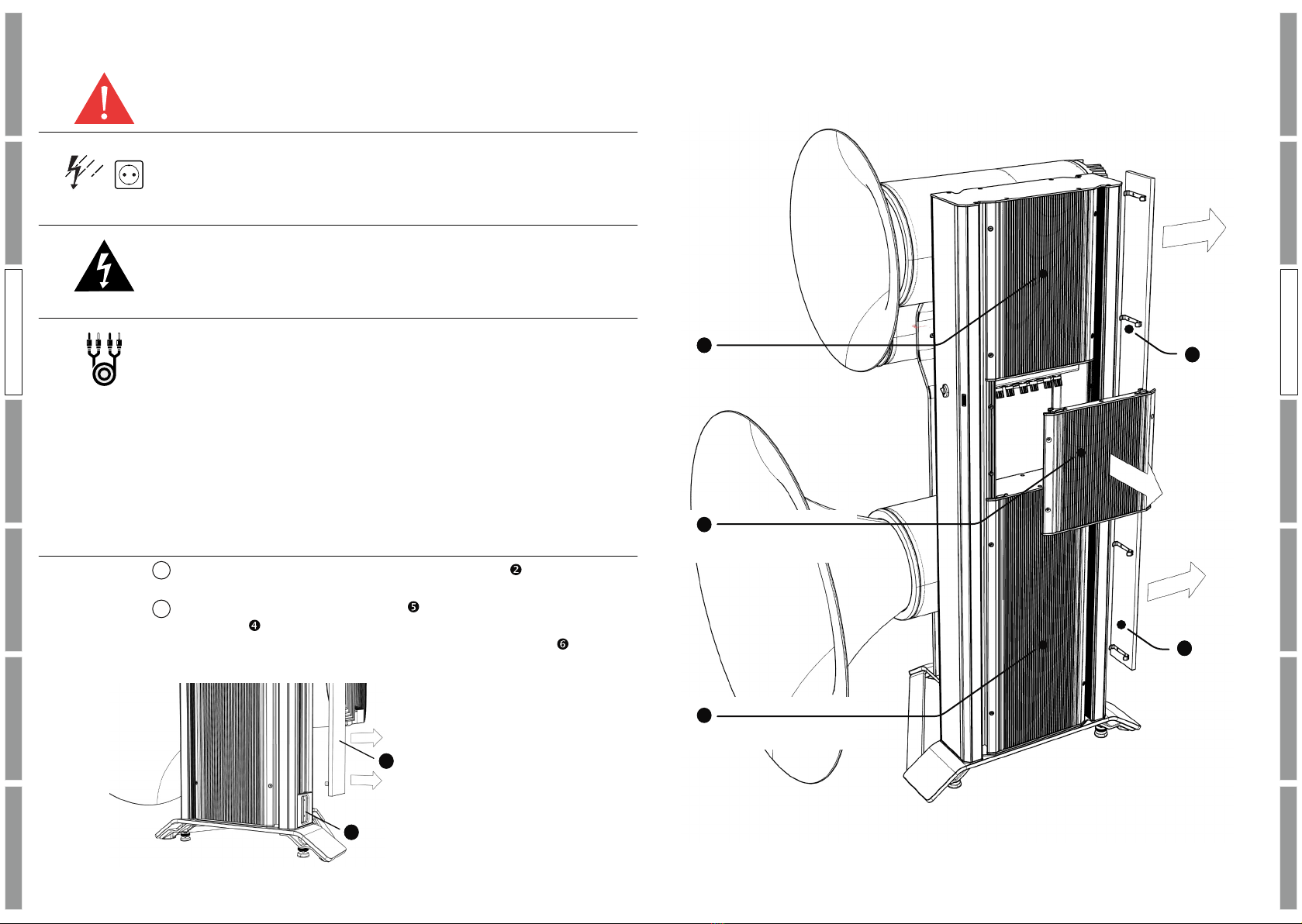
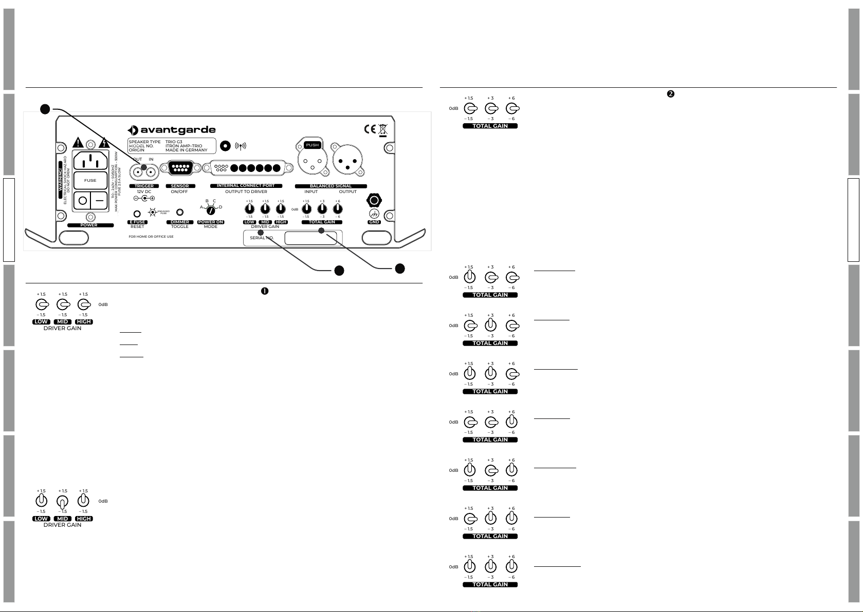
OPERATION – TRIO G3 ITRON VERSION
POWER MODES
The mains power switch has an “O” OFF–position & an “1” ON–
position. For operation switch to the ON position.
The TRIO G3 features an illuminated sensor switch on its front
side to turn the speaker ON.
ORANGE light = STANDBY
WHITE light = ON
PURPLE light = OTA firmware update (optional future upgrade only)
The brightness of the light can be adjusted with the DIMMER
TOGGLE button , toggling through 8 x intensities.
4 x different power ON/OFF modes can be selected with the POWER
ON mode selector . Use a screwdriver to switch the modes.
�newly selected modes will only become active after the mains
power switch has been shortly switched OFF.
MODE A speaker is ON upon powering it up with the mains
power switch . To be used for remote controlled AC
power sockets. The frontal sensor switch may still
be used to switch into standby mode, but upon next
power cycle the speaker will turn ON again directly.
MODE B speaker is ON when a 12V trigger voltage is detected at
the remote-trigger socket . The speaker will
automatically switch OFF, when the 12V trigger voltage
is switched OFF.
MODE C the frontal sensor switch is used to toggle between
speaker ON & STANDBY.
MODE D speaker is switched ON & STANDBY by remote control
signal (not available upon release; optional future upgrade only).
CONNECTION – TRIO G3 ITRON VERSION
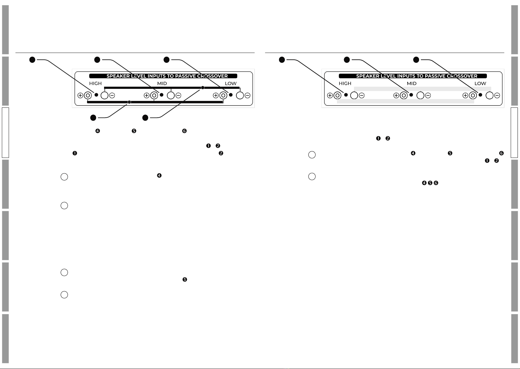
BALANCED XLR CONNECTION
Line level connections feature balanced XLR connectors/terminals.
The pin assignment of these follows the EIA RS-297-A standard:
PIN 1 = GND, PIN 2 = HOT, PIN 2 = COLD. Never use cables with
differing pin assignment! This will deteriorate the sound quality and
can damage the amplifiers and/or the active power modules of the
subwoofers.
Connect the line level output of your preamplifier with the balanced
line level input of the TRIO G3 speaker with an XLR cable.
Connect the balanced XLR daisy chain output of the TRIO G3
speaker and the balanced XLR input of the SPACEHORNS with the
long XLR jumper cable. The jumper cable is included in the
accessory box.
If you use more than 1 x subwoofer per channel, connect the
balanced XLR daisy chain output of the SPACEHORNS No.1 and the
balanced XLR line level input of the SPACEHORNS No.2 with the
shorter XLR jumper cable. The jumper cable is included in the
accessory box.
Only now, connect the AC power of the components to a
household AC outlet and turn on the ITRON module and the
subwoofer.
TRIGGER SENSOR
12V DC
OUT IN
ON/OFF
POWER ONDIMMER TOTAL GAIN GND
MODETOGGLE
E FUSE
RESET DRIVER GAIN
INTERNAL CONNECT PORT
OUTPUT TO DRIVER
LOW MID HIGH
+ 1.5
–1.5
+ 1.5
–1.5
+ 1.5
–1.5
0dB
+ 1.5
–1.5
+ 3
–3
+ 6
–6
INPUT OUTPUT
BALANCED SIGNAL
A D
B C
ENGAGED
FUSE
POWER
FOR HOME OR OFFICE USE
110 – 240V ~ 50/60HZ
MAX POWER CONSUMPTION – 500W
FUSE 2.5 A SLOW
WARNING!
ELECTRICAL SHOCK HAZARD
DO NOT OPEN!
SERIAL NO.
TRIO G3
ITRON AMP–TRIO
MADE IN GERMANY
SPEAKER TYPE
MODEL NO.
ORIGIN
PUSH
FUSE
PUSH
11
13
18 12
14 1715 16
1
2
3
4
1
2
3
OPERATION TRIO
OPERATION TRIO