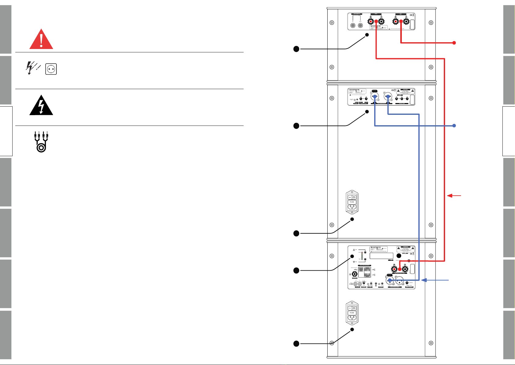
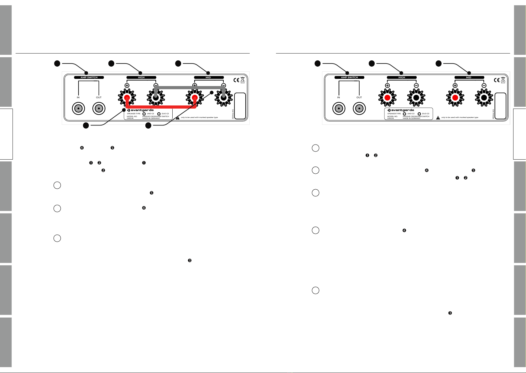
CONNECTION – PASSIVE VERSION
BI–WIRING
To operate the system in BI-Wiring or BI-Amping mode, the 2 x OFC
2-way bridges & must be removed.
Open the screw caps of the tweeter and midrange speaker ter‐
minals and remove the two OFC 2-way bridges & .
Connect the speaker output of your power amplifier (or integrated
amplifier) to the speaker terminals of the loudspeaker, using a sep‐
arate cable for each terminal. The same applies if you are using mul‐
tiple amplifiers for treble and midrange.
Connect the HIGH terminal of the speaker and the speaker input
terminals of the DSP subwoofer amplifier with the jumper cable.
The jumper cable is included in the accessory box.
The jumper cables have hollow banana plugs which are open at the
rear. This way it is possible to stack multiple speaker cables to the
same speaker terminal.
Only now connect the components' power cords to a household
outlet and turn on the subwoofer and other equipment.
The inputs and outputs of the AMP SWITCH are exclusively avail‐
able on devices with ITRON amplifier (incl. the AMP SWITCH cir‐
cuitry) and are used for remote switching between PASSIVE cross‐
over and ITRON amplifier.
16 17
SAFETYINSTALLATIONOPERATION SUBFINE TUNING
MISC
WARRANTY OPERATION
SAFETYINSTALLATIONOPERATION SUBFINE TUNING
MISC
WARRANTY OPERATION
CONNECTION – PASSIVE VERSION
SINGLE–WIRING
High and mid have separate speaker terminals. In the standard
conf iguration these connectors interconnected with 2 x OFC 2-way
bridges & . One bridge interconnects all "+" terminals, the
other bridge interconnects all "-" terminals.
Connect the Speaker-Output of your power (or integrated) amplifier
to the Speaker-MID connector of the speakers.
Connect the HIGH terminal of the speaker and the speaker input
terminals of the DSP subwoofer amplifier with the jumper cable.
The jumper cable is included in the accessory box.
Only now connect the components' power cords to a household
outlet and turn on the subwoofer and other equipment.
The inputs and outputs of the AMP SWITCH are exclusively avail‐
able on devices with ITRON amplifier (incl. the AMP SWITCH cir‐
cuitry) and are used for remote switching between PASSIVE cross‐
over and ITRON amplifier.
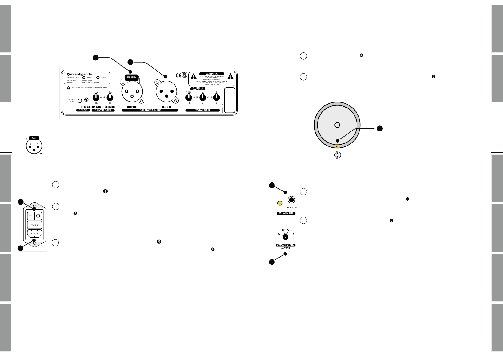
+ 1.5
+ 3
+ 6
WARNING
ELECTRICAL SHOCK HAZARD
DO NOT OPEN!
110 – 240V ~ 50/60HZ
MAX POWER CONSUMPTION – 570W
POWER OUTPUT – 530W RMS
FUSE 2.5 A SLOW
0dB 0dB
–1.5
–3
–6
TOTAL GAINDRIVER GAIN
MIDRESET HIGH IN OUT
BALANCED INPUT
+ 1.5
–1.5
+ 1.5
–1.5
0dB
ENGAGED
FUSE
E FUSE
UNO G3 DUO G3
ITRON AMP
MADE IN GERMANY
SPEAKER TYPE
MODEL NO.
ORIGIN
SERIAL NO.
only to be used with marked speaker type
IN OUT
MID
AMP SWITCH
SERIAL NO.
PASSIVE CROSSOVER SWITCH
MADE IN GERMANY
MODEL NO.
ORIGIN
SPEAKER TYPE UNO G3 DUO G3
only to be used with marked speaker type
MIDHIGH MID
MID
PUSH
1
1413 15
1
2
3
1
2
3
4
OPERATION
OPERATION
12
+ 1.5
+ 3
+ 6
WARNING
ELECTRICAL SHOCK HAZARD
DO NOT OPEN!
110 – 240V ~ 50/60HZ
MAX POWER CONSUMPTION – 570W
POWER OUTPUT – 530W RMS
FUSE 2.5 A SLOW
0dB 0dB
–1.5
–3
–6
TOTAL GAINDRIVER GAIN
MIDRESET HIGH IN OUT
BALANCED INPUT
+ 1.5
–1.5
+ 1.5
–1.5
0dB
ENGAGED
FUSE
E FUSE
UNO G3 DUO G3
ITRON AMP
MADE IN GERMANY
SPEAKER TYPE
MODEL NO.
ORIGIN
SERIAL NO.
only to be used with marked speaker type
IN OUT
MID
AMP SWITCH
SERIAL NO.
PASSIVE CROSSOVER SWITCH
MADE IN GERMANY
MODEL NO.
ORIGIN
SPEAKER TYPE UNO G3 DUO G3
only to be used with marked speaker type
MIDHIGH MID
MID
PUSH
1413 15
5
� �
�