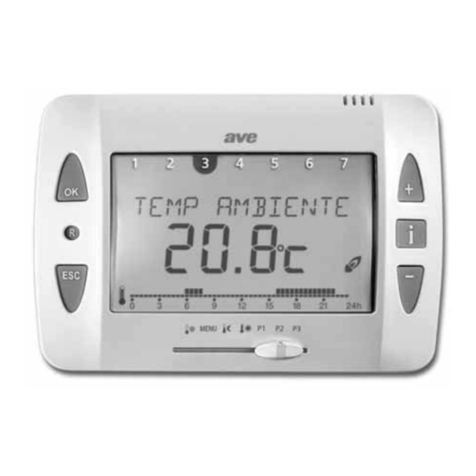
AVE 44 085SW Series User manual

IIssttrruuzziioonniippeerrll’’uussoo11
Termostato elettronico 230V~ a display
44..085SW
IInnssttrruuccttiioonnssffoorrUUssee1100
Electronic thermostat 230V~ display
44..085SW
IInnssttrruuccttiioonnssdd’’uuttiilliissaattiioonn1199
Thermostat électronique 230V~ à écran
44..085SW
IInnssttrruucccciioonneessppaarraaeelluussoo2288
Termostato electrónico 230V~ con display
44..085SW
C.539rev01 18-07-2008 16:33 Pagina 2

1
ITALIANO
2 Avvertenze per la sicurezza
Il collegamento e l’installazione di apparecchi elettrici vanno eseguiti
unicamente da personale professionalmente qualificato, nel rispetto
delle disposizioni nazionali e di sicurezza vigenti.
Qualsiasi intervento o modifica all’apparecchio comporta la cessazio-
ne immediata della garanzia.
Indice
1 Utilizzo previsto dal costruttore 1
2 Avvertenze per la sicurezza 1
3 Descrizione ed installazione 2
3.1 Descrizione dell’apparecchio 2
3.2 Esempi di allacciamento elettrico 3
3.2.1 Riscaldamento 3
3.2.2 Condizionamento 4
3.2.3 Riduzione e comando remoto 5
4 Modalità d’uso dell’apparecchio 5
4.1 Funzione dei tasti 5
4.1.1 Pulsante 5
4.1.2 Pulsanti e5
4.1.3 Pulsante 5
4.2 Ingresso regime ridotto (morsetto )5
4.3 Ingresso comando remoto (morsetto )6
4.3.1 Attivazione stabile 6
4.3.2 Attivazione temporizzata 6
5 Funzioni e modalità di configurazione 7
5.1 Blocco tastiera 7
5.2 Regime di funzionamento: Estate o Inverno 7
5.3 Riduzione 7
5.4 Soglia antigelo 7
5.5 Compensazione termica 7
5.6 Differenziale termico (isteresi) 7
5.7 Temporizzazione 8
5.8 Reset 8
6 Funzionamento 8
6.1 Accensione 8
6.2 Funzionamento ordinario 8
7 Dati tecnici 8
7.1 Condizioni climatiche 9
7.2 Conformità normativa 9
8 Manutenzione 9
9 Smaltimento dell’apparecchio 9
1 Utilizzo previsto dal costruttore
Il 4444....008855SSWWè un termostato elettronico a display alimentato da rete 230V~
50Hz, che permette di regolare la temperatura ambiente. Realizzato in 2 moduli del
sistema 44, il termostato permette di accendere e spegnere tutti i tipi di apparec-
chi ad energia elettrica, come ad esempio pompe di circolazione, bruciatori o val-
vole di miscelazione a motore. L’impiego del termostato è consigliato in locali ad
uso domestico.
Deve essere installato in scatole da incasso o da parete ad un’altezza di circa 1,5
metri dal piano di calpestio, in una posizione idonea alla corretta rilevazione della
temperatura ambiente, evitando l’installazione in nicchie, dietro porte e tende o
zone influenzate da fonti di calore o fattori atmosferici; iinnppaarrttiiccoollaarreessiiddeevvee
eevviittaarreell’’iinnssttaallllaazziioonneessuuppaarreettiippeerriimmeettrraalliiooiinnaassssoocciiaazziioonnee
aadd
aappppaarreecccchhiicchheeggeenneerraannooccaalloorree((eess..rreeggoollaattoorriioollaammppaaddee))..
Per utilizzare il termostato in conformità con le regole previste dal costruttore, è
necessario attenersi alle istruzioni d’uso e di installazione. Ogni altro utilizzo del
termostato è da considerarsi improprio. Il costruttore declina qualsiasi responsa-
bilità derivante da danni dovuti ad un uso improprio dell’apparecchio.
C.539rev01 18-07-2008 16:33 Pagina 1

2ITALIANO
3 Descrizione ed installazione
3.1 Descrizione dell’apparecchio
Indicazione attivazione forzatura da
remoto (ingresso )
Indicazione attivazione protezione
antigelo
Tasto (selezione
modo funzionamento)
Tasto (attivazione
retroilluminazione)
Tasti e (decremento e
incremento del valore
visualizzato)
Indicazione blocco della tastiera
Indicazione condizionamento
attivato (in estate)
Indicazione riscaldamento attivato
(in inverno)
Indicazione attivazione regime
ridotto (ingresso )
Indicazione attivazione
temporizzata in corso
Indicazione termostato spento
Nota: alla pressione di un qualsiasi tasto si ha l’attivazione della retroilluminazione blu che consente la lettura del display e l’individuazione della funzione del tasto anche
in mancanza di luce.
Sulla parte frontale si trovano:
- quattro pulsanti che consentono l'impostazione della temperatura ambiente e la programmazione
dei parametri del dispositivo;
- un display LCD per l’indicazione della temperatura e dello stato di funzionamento del termostato.
C.539rev01 18-07-2008 16:33 Pagina 2

3
ITALIANO
3.2 Esempi di allacciamento elettrico
3.2.1 Riscaldamento
L
N
C
NA
: bruciatore, pompa circolazione, ecc.
C
230V~ L
N
C
Figura 1b
Figura 1a
E' possibile alimentare direttamente l'utilizzatore tramite il contatto in deviazione (fig. 1a), oppure sfruttare quest'ultimo per trasmettere un "consenso-caldaia" libero da
potenziale (fig. 1b).
L
N
C
NA
: contatto NA per consenso caldaia
230V~ L
N
C
C
C.539rev01 18-07-2008 16:33 Pagina 3

4ITALIANO
3.2.2 Condizionamento
E' possibile alimentare direttamente l'utilizzatore tramite il contatto in deviazione (fig. 2a), oppure sfruttare quest'ultimo per trasmettere un "consenso-condizionatore" libe-
ro da potenziale (fig. 2b).
L
N
C
NA
F: condizionamento
F
230V~ L
N
Figura 2b
Figura 2a
L
N
C
NA
F: contatto NA per consenso condizionamento
F
230V~ L
N
C.539rev01 18-07-2008 16:33 Pagina 4

4 Modalità d’uso dell’apparecchio
4.1 Funzione dei tasti
4.1.1 Pulsante
La pressione del pulsante attiva la retroilluminazione per permettere una migliore
lettura della temperatura misurata.
4.1.2 Pulsanti e
Una pressione singola dei pulsanti di decremento/incremento visualizzerà l’attua-
letemperaturaimpostata(setpoint)senzamodificaalcuna;agendonuovamentesui
pulsanti sarà possibile impostare il valore di temperatura desiderato (setpoint).
4.1.3 Pulsante
Unapressionesingoladelpulsante visualizzerà l’attuale stato di funzionamento del
termostato (acceso) - (regime ridotto) -
OFF
(spento); agendo nuovamen-
tesul pulsante sarà possibile selezionare/variarelostatodifunzionamentodeside-
rato[glistatidifunzionamento (Ridotto)e
OFF
(spento)vengonoindicatianche
con i relativi simboli: e
OFF
].
4.2 Ingresso regime ridotto (morsetto )
L’ingresso consente di variare con una sola operazione il livello di comfort (set-
point) impostato sul termostato, ad esempio per il periodo notturno. Il valore di
questo spostamento, espresso in gradi Celsius, viene sottratto al valore imposta-
to quando si è in regime di funzionamento invernale e viene sommato in regime di
funzionamento estivo (vedi paragrafo 5.3). L’attivazione di questo regime è eviden-
ziata dall’accensione sul display dell’icona .
Il contatto NA esterno deve essere collegato alla fase (morsetto L) (vedi paragrafo
3.2.3.)
Se il termostato è acceso (stato di funzionamento ):
• chiudendo il contatto, dopo circa 1 secondo il termostato si porta in stato di
regime ridotto ( ) (simbolo acceso);
5
ITALIANO
3.2.3 Riduzione e comando remoto
L
N
C
NA
C
230V~
L
N
Funzioni attivabili con contatto esterno NA collegato al morsetto di fase L (fig. 3).
Figura 3
C.539rev01 18-07-2008 16:33 Pagina 5

6ITALIANO
• mantenendo il contatto chiuso è comunque possibile spegnere manualmente
il termostato (OFF) agendo sul pulsante ;
• aprendo il contatto, il termostato si riporta sullo stato impostato precedente-
mente.
Se il termostato è spento (stato di funzionamento OFF):
• chiudendo il contatto il termostato rimane spento (OFF) (simbolo acceso);
• mantenendo il contatto chiuso è comunque possibile porre il termostato in
stato di funzionamento con regime ridotto ( ) agendo sul pulsante ;
• aprendo il contatto, il termostato si riporta sullo stato impostato precedente-
mente.
4.3 Ingresso comando remoto (morsetto )
L’ingresso consente di attivare la termoregolazione in modo stabile o temporizza-
to, tramite un contatto esterno. E’ utile in genere per accensioni da remoto del ter-
mostato (es. da combinatori telefonici, ecc.).
Il contatto NA esterno deve essere collegato alla fase (morsetto L) (vedi paragrafo
3.2.3).4.3.1 Attivazione stabile
Se il termostato è spento (stato di funzionamento OFF):
• chiudendo il contatto, dopo 5 secondi, il termostato si accende ( ) (sim-
bolo acceso);
• mantenendo ilcontatto chiuso,nonè possibilespegnereil termostato(OFF);
• aprendo il contatto, il termostato si spegne (OFF).
Se il termostato è acceso (stato di funzionamento ):
• chiudendo il contatto, dopo 5 secondi, il termostato rimane acceso ( )
(simbolo acceso);
• mantenendo ilcontatto chiuso,nonè possibilespegnereil termostato(OFF);
• aprendo il contatto, il termostato si spegne (OFF).
Se il termostato è in regime di riduzione (stato di funzionamento ) (simbolo
acceso):
• chiudendo il contatto, dopo 5 secondi, il termostato si porta in stato di fun-
zionamento (simbolo acceso) salvo che il regime di riduzione sia deter-
minato dall’ingresso ; in tal caso verrà mantenuto tale stato (simboli e
accesi);
• aprendo il contatto, il termostato si spegne (OFF). Nota: nell’eventualità che
il regime di riduzione sia determinato dall’ingresso , il termostato si man-
terrà in regime ridotto(simbolo e OFF accesi).
4.3.2 Attivazione temporizzata
Se il termostato è spento (stato di funzionamento OFF):
• chiudendo il contatto per un tempo compreso tra 1 secondo e 5 secondi, il
termostato si accende ( ) temporizzato (simbolo acceso). Il termostato
rimarrà attivo per il tempo impostato (vedi paragrafo 5.7), dopodichè si spe-
gnerà (OFF).
Se il termostato è acceso (stato di funzionamento ):
• chiudendo il contatto per un tempo compreso tra 1 secondo e 5 secondi, il
termostato si porta in stato di funzionamento temporizzato (simbolo
acceso). Il termostato rimarrà attivo per il tempo impostato (vedi paragrafo
5.7), dopodichè si spegnerà (OFF).
Se il termostato è in regime di riduzione (stato di funzionamento ) (simbolo
acceso):
• chiudendo il contatto per un tempo compreso tra 1 secondo e 5 secondi, il
termostato si porta in stato di funzionamento temporizzato (simbolo
acceso). Il termostato rimarrà attivo per il tempo impostato (vedi paragrafo
5.7), dopodichè si spegnerà (OFF).
Nota: nell’eventualità che il regime di riduzione sia determinato dall’ingresso,
chiudendo il contatto per un tempo compreso tra 1 secondo e 5 secondi, il termo-
stato si porta in stato di regime di riduzione temporizzato (con i simboli e
accesi). Alla scadenza del tempo impostato (vedi paragrafo 5.7), se l’ingressoè
ancora chiuso, il termostato permane nel regime di riduzione (simbolo acceso).
C.539rev01 18-07-2008 16:33 Pagina 6

5 Funzioni e modalità di configurazione
La pressione contemporanea dei tasti e , per almeno 5 secondi, permetterà
l’accesso al menu di configurazione.
Nel menù di configurazione, premendo il pulsante , si potrà selezionare/passa-
re alla voce desiderata ed, una volta selezionata, tramite i pulsanti emodi-
ficarne l’impostazione. L’uscita dal menu di configurazione potrà essere fatta pre-
mendo in ogni situazione il pulsante , oppure attendendo la scadenza del time-
out di circa 60 sesondi.
I passi di configurazione sono proposti nella sequenza ciclica con cui vengono
presentati sul display:
5.1 Blocco tastiera
La funzione “blocco tastiera” permette di bloccare la tastiera per evitare di modifi-
care accidentalmente il setpoint (valore di temperatura desiderato) impostato e/o
lo stato di funzionamento del termostato. Tramite i pulsanti everrà visua-
lizzata alternativamente la scritta “OFF/ ”con il simbolo , ad indicare rispet-
tivamente la condizione del blocco disattivato/attivato.
Nota: l’attivazione del blocco tastiera non inibisce l’accesso al menu di configura-
zione, necessario ad impostarne la disattivazione.
Condizione di fabbrica: OFF
5.2 Regime di funzionamento: Estate o Inverno
Tramite i pulsanti everranno visualizzati alternativamente i simboli e
, ad indicare il regime di funzionamento del termostato (rispettivamente esta-
te=condizionamento o inverno=riscaldamento).
Condizione di fabbrica: Inverno ( )
5.3 Riduzione
Ilvalore di “riduzione”èunvalore “assoluto” che verràsommatoalsetpoint impo-
stato per ottenere una riduzione di consumo, tipicamente richiesta nelle ore not-
7
ITALIANO
turne. Il valore di “riduzione” verrà visualizzato con il segno “- (meno)” nel caso il
termostato sia in regime di funzionamento “Inverno”, con il segno “+ (più)” nel
caso il termostato sia in regime di funzionamento “Estate” (a significare che tale
valoreverràsottrattoosommatoalsetpointimpostatoaseconda del regime difun-
zionamento); tale valore verrà visualizzato assieme al simbolo di riduzione not-
turna. Tramite i pulsanti esi potrà eseguire una regolazione tra -0,5 e -5,0
°C nel caso il termostato si trovi in regime di funzionamento “Inverno” (oppure tra
+0,5 e +5,0 °C nel caso il termostato si trovi in regime di funzionamento “Estate”).
Condizione di fabbrica: 3,0 °C
5.4 Soglia antigelo
Il valore impostato verrà visualizzato assieme al simbolo (antigelo). Il valore di
“soglia antigelo” è un valore di temperatura di sicurezza al di sotto della quale il
termostato attiverà il relè d’uscita anche se spento (stato di funzionamento OFF).
Tramite i pulsanti esi potrà eseguire una regolazione tra +2,0 e +10,0 °C.
Condizione di fabbrica: 5,0 °C
5.5 Compensazione termica
Nelcasoin cui non sia stato possibilemontare il termostato in una posizioneidea-
le, ossia se il termostato si trova su una parete esterna, accanto al camino, ecc.,
potrebbero verificarsi delle differenze fra la temperatura rilevata dal termostato e la
temperatura ambiente effettiva. Per questi casi, sussiste la possibilità di imposta-
re una compensazione termica (esempio: la differenza fra la temperatura ambiente
effettiva e quella indicata dal termostato è di 2 °C, ossia la temperatura ambiente
viene indicata con 2 °C superiori: valore di compensazione -2 °C).
Il valore impostato verrà visualizzato con una scritta “ 0.0”. Tramite i pulsanti
esi potrà eseguire una regolazione tra -5,0 e +5,0 °C.
Condizione di fabbrica: 0
5.6 Differenziale termico (isteresi)
Per differenziale termico si intende la differenza tra il valore di temperatura impo-
stato e l’effettiva temperatura di accensione o di spegnimento dell’impianto.
C.539rev01 18-07-2008 16:33 Pagina 7

8ITALIANO
Adeguando il differenziale termico al tipo di impianto se ne evitano continue
accensioni e spegnimenti; impianti ad alta inerzia (ad esempio impianti con radia-
tori in ghisa) necessitano di un valore basso di differenziale termico, mentre impi-
anti a bassa inerzia (ad esempio ventil-convettori) necessitano di un valore alto.
(esempio: impostando, in inverno, la temperatura ambiente a 20 °C e il differen-
ziale termico a 0,3 °C, l’impianto si accenderà quando la temperatura ambiente
scenderà a 20 °C e si spegnerà quando raggiungerà i 20,4 °C).
Il valore impostato verrà visualizzato con una scritta “ 0.3”. Tramite i pulsanti
esi potrà eseguire una regolazione tra 0,2 e 2,5 °C.
Condizione di fabbrica: 0,3 °C
5.7 Temporizzazione
Se l’ingresso di comando remoto viene chiuso per un tempo compreso tra 1
secondo e 5 secondi il termostato viene attivato a tempo (vedi paragrafo 4.3.2).
Tramite i pulsanti esi potrà eseguire una regolazione tra 0,5 ore e 5 ore
con passi di 0,5 ore.
Condizione di fabbrica: 2 ore
5.8 Reset
La scritta “ ” lampeggiante sta ad indicare la possibilità di accedere alla fun-
zione di “reset” che porterà l’apparecchio alle impostazioni di fabbrica.
Il reset verrà eseguito mantenendo la pressione del pulsante , del pulsante
o contemporanea dei pulsanti eper almeno 5 secondi: l’esecuzione del
reset è visualizzata con l’accensione di tutti i simboli del display.
6 Funzionamento
6.1 Accensione
All’atto dell’alimentazione da rete la fase di accensione dura circa 8 secondi (il
tempo necessario ad acquisire un valore di temperatura). Durante la fase di accen-
sione viene eseguito il test dell’intero display e viene poi visualizzata la versione
del firmware (esempio F0.0).
6.2 Funzionamento ordinario
Nelnormale funzionamento, ildispositivo visualizzeràla temperatura misuratae lo
stato del relè (utilizzando l’opportuno simbolo in inverno o in estate, a
seconda del regime di funzionamento impostato).
Selatemperaturamisurata eccedesse il range di misura dellatemperaturaambien-
te, il display indicherebbe la scritta “+40.0” lampeggiante se la temperatura ecce-
desse il limite massimo, o “–00.0” lampeggiante se la temperatura fosse inferiore
al limite minimo.
Qualsiasi intervento manuale che comporti la variazione dello stato
del relè d’uscita viene trasmesso a quest’ultimo dopo che la retroil-
luminazione di display e tastiera si spegne (i simboli e vengo-
no invece aggiornati istantaneamente).
7 Dati tecnici
• Ingombro: 2 moduli Sistema 44
• Grado di protezione: IP40 in conformità con EN 60529-1
• Morsettiera a 7 morsetti accessibili sul lato posteriore
• Tensione alimentazione: 230 Vca 50-60 Hz
• Variazione ammessa: 190 Vca ÷ 253 Vca
• Assorbimento massimo: 20 mA a 230 Vca
• Uscita (morsetti NA-C-NC): relè bistabile ad 1 contatto in deviazione libero
da potenziale. Nota: in caso di assenza di rete il contatto d’uscita
mantiene lo stato preesistente alla mancanza di rete
• Carico nominale:
- ohmico (cosϕ1): 2A a 250 Vca
- induttivo (cosϕ0,4 ): 2A a 250 Vca
• Aggiornamento della temperatura visualizzata: ogni 8 secondi
• Tipo di regolazione: ON/OFF
C.539rev01 18-07-2008 16:33 Pagina 8

9
ITALIANO
• Altitudine max: 2000 m s.l.m.
7.2 Conformità normativa
• CEI EN 60730-1
• CEI EN 60730-2-9
8 Manutenzione
Il termostato ambiente 44..085SW non necessita di manutenzione. L’apparecchio
va pulito solamente con un panno morbido ed asciutto.
9 Smaltimento dell’apparecchio
Una volta terminato l’esercizio, l’apparecchio deve essere smaltito in conformità
con le normative vigenti e nel rispetto dell’ambiente.
In caso di dubbi, rivolgersi al rappresentante del costruttore dell’apparecchio nel
proprio Paese.
• Campo di misura della temperatura ambiente: da 0 °C a 40 °C
• Campo di impostazione temperatura:
- da 2 °C a 10 °C (antigelo)
- da 5 °C a 35 °C (riscaldamento o condizionamento)
• Precisione di regolazione: ±0,5 °C max
• Compensazione termica: ± 5 °C
• Differenziale termico: regolabile da 0,2 °C a 2,5 °C
• Risoluzione di lettura: 0,1 °C
• Risoluzione delle impostazioni: 0,1 °C
• Principali funzioni:
- possibilità di impostazione di 3 livelli di temperatura: comfort, ridotta,
antigelo
- scelta regime funzionamento: estate/inverno
- comando remoto della funzione regime ridotto
- attivazione (stabile o temporizzata) da remoto del termostato
- possibilità blocco tastiera
- memorizzazione di tutte le impostazioni
• Classe di protezione: Il in conformità con EN 60730-1
• Tipo di apertura contatti: microdisconnessione
• Tipo di azione: 1B
• Indice di tracking: PTI175
• Grado di inquinamento: 2 (normale)
• Classe del software: A
7.1 Condizioni climatiche
• Temperatura e umidità relativa di riferimento: 25 °C; UR 65%
• Campo temperatura ambiente di funzionamento: da -10 °C a +50 °C
• Umidità relativa massima: 90% a 35 °C
C.539rev01 18-07-2008 16:33 Pagina 9

10 ENGLISH
2 Safety warning
The connection and installation of the electrical apparatuses must be
done only by qualified professionals, in compliance with national and
safety regulations in force.
Any work on or modification to the apparatus will cause the guarantee
to be voided immediately.
Index
1 Use planned by the Manufacturer 10
2 Safety warnings 10
3 Description and installation 11
3.1 Description of apparatus 11
3.2 Examples of electrical connection 12
3.2.1 Heating 12
3.2.2 Air conditioning 13
3.2.3 Reduction and remote control 14
4 Ways of using the apparatus 14
4.1 Key Functions 14
4.1.1 Key 14
4.1.2 Keys and 14
4.1.3 Key 14
4.2 Reduced capacity entry (terminal )14
4.3 Remote control Entry (terminal )15
4.3.1 Stable activation 15
4.3.2 Activation with timer 15
5 Operation and configuration methods 16
5.1 Key Lock 16
5.2 Operating method: Summer or Winter 16
5.3 Reduction 16
5.4 Anti-freeze threshold 16
5.5 Thermal compensation 16
5.6 Thermal differential (hysteresis) 16
5.7 Timer 17
5.8 Reset 17
6 Operation 17
6.1 Switching on 17
6.2 Ordinary operation 17
7 Technical data 17
7.1 Weather conditions 18
7.2 Conformity with regulations 18
8 Maintenance 18
9 Disposal of the apparatus 18
1 Use planned by the Manufacturer
The 4444....008855SSWWis an electronic thermostat with display fed by 230V~ 50Hz
mains, that allows regulating room temperature. It is made in 2 modules of the
system 44, the thermostat allows any electrical appliance to be switched on and
off, such as circulation pumps, burners or motor-driven mixing valves. The use of
the thermostat is advisable in rooms for domestic use.
It must be installed in flushed or wall mounting boxes at a height of approximate-
ly 1,5 meters from the walking surface, in a position suitable for the correct rea-
ding of room temperature, avoiding installation in niches, behind doors and cur-
tains or areas influenced by heat sources or atmospheric factors; iinnppaarrttiiccuullaarr
aavvooiiddiinnssttaalllliinnggtthheeaappppaarraattuussoonnppeerriimmeetteerrwwaallllssoorrnneeaarrhheeaattssoouurr--
cceess
((ee..gg..rreegguullaattoorrssoorrllaammppss))..
To use the thermostat in conformity with the rules established by the manufacturer
it is necessary to keep to the instructions for use and installation. Any other use
of the thermostat is to be considered improper. The manufacturer is not responsi-
ble for any damage due to an improper use of the apparatus.
C.539rev01 18-07-2008 16:33 Pagina 10

Note: when any key is pressed the blue back-lighting comes on to allow reading the display and identifying the function of the key even when there are no lights.
11
ENGLISH
3 Description and installation
3.1 Description of the apparatus
Indicates activation of forcing from
remote (input )
Indicates activation of
anti-freeze protection
Key (select
operating mode)
Key (activation
of back-lighting)
Keys and (decrease
increase and
of viewed value)
Indicates key lock
Indicates activation of air
conditioning (in summer)
Indicates activation of
heating (in winter)
Indicates activation of reduced
capacity (output )
Indicates activation
with timer
Indicates thermostat off
On the front part there are:
- four push button keys to set room temperature and to programme the parameters of the device;
- an LCD display to show the temperature and the state of operation of the thermostat.
C.539rev01 18-07-2008 16:33 Pagina 11

12 ENGLISH
3.2 Examples of electrical connection
3.2.1 Heating
L
N
C
NO
C
230V~ L
N
C : burner, circulation pump, ecc.
Fig. 1b
Fig. 1a
It is possible to feed the user directly through a contact in deviation (fig. 1a), or exploit this to transmit a "boiler-consent" free from potential (fig. 1b).
L
N
C
NO
: NO contact to consent boiler
230V~ L
N
C
C
C.539rev01 18-07-2008 16:33 Pagina 12

13
ENGLISH
3.2.2 Air Conditioning
It is possible to feed the user directly through the contact in deviation (fig. 2a), or exploit this to transmit a "conditioner-consent" free from potential (fig. 2b).
L
N
C
NO
F: conditioning
F
230V~ L
N
Fig. 2b
Fig. 2a
L
N
C
NO
F: NO contact to consent conditioning
F
230V~ L
N
C.539rev01 18-07-2008 16:33 Pagina 13

14 ENGLISH
3.2.3 Reduction and remote control
L
N
C
NO
C
230V~
L
N
Operations that can be activated with external NO contact connected to the phase
terminal L (fig. 3).
Fig. 3
4 Ways of using the apparatus
4.1 Key Functions
4.1.1 Key
The pressure of the key activates the rear-lighting to allow a better reading of the
measured temperature.
4.1.2 Keys and
A single pressure on the decrease/increase keys views the set temperature (set
point) without modifying anything; press the keys again to set the required tempe-
rature value (set point).
4.1.3 Key
Press the key once to view the current state of operation of the thermostat (on)
- (reduced capacity) - OFF (off); press the key again to adjust the required state
ofoperation (Reduced) and OFF operation modesare also shown withthe rela-
tive symbols: and OFF).
4.2 Reduced capacity entry (terminal )
The entry allows varying, with one single operation, the comfort level (set point)
set on the thermostat, at night for example. The value of this change, given in
degrees Celsius, is subtracted from the set value when operating in winter mode
and is added when running in summer mode (see paragraph 5.3). The activation
of this running mode is shown on the display of icon .
The NO external contact must always be connected to the phase (terminal L) - (see
paragraph 3.2.3).
If the thermostat is on (Operation status):
• When the contact is closed, after about 1 second the thermostat goes to
reduced capacity ( ) (symbol on);
• Keeping the contact closed it is still possible to switch off the thermostat
manually (OFF), acting on the button ;
C.539rev01 18-07-2008 16:33 Pagina 14

15
ENGLISH
• Opening the contact the thermostat will return to the state set previously.
If the thermostat is off (operation status OFF):
• When the contact is closed the thermostat remains off (OFF) (symbolon);
• Keeping the contact closed it is still possible to position the thermostat to
reduced capacity ( ) acting on the button ;
• Opening the contact the thermostat will return to the state set previously.
4.3 Remote control Entry (terminal )
The entry allows activating the thermoregulation in a stable mode or with timer, by
using an external contact. It is generally useful to switch on the thermostat using
remote controls (e.g. telephone controllers etc.).
The NA external contact must be connected to the phase (terminal L) – (see para-
graph 3.2.3).
4.3.1 Stable activation
If the thermostat is off (Operation status OFF):
• When thecontact isclosed, afterabout 5seconds thethermostat switcheson
( ) (symbol on);
• Keeping the contact closed it is not possible to switch off (OFF) the
thermostat;
• Opening the contact, the thermostat switches off (OFF).
If the thermostat is on (Operation status ):
• when the contact is closed, after about 5 seconds the thermostat remains on
( ) (symbol on);
• keeping the contact closed it is not possible to switch off (OFF) the
thermostat;
• opening the contact, the thermostat switches off (OFF).
If the thermostat is in reduced capacity (operation status ) (symbol on):
• when the contact is closed, after about 5 seconds the thermostat goes to
operation status (symbol on) except where the reduction capacity
is determined by the entry; in this case this status will be maintained
(symbol andon);
• opening the contact the thermostat switches off (OFF). NNoottee::should the
reduction capacity be determined by the entry, the thermostat will keep the
reduced capacity (symboland OFF on).
4.3.2 Activation with timer
If the thermostat is off (Operation status OFF):
• when the contact is closed for a time going from 1 to 5 seconds the thermostat
will switch on ( ) with timer (symbol on). The thermostat will be active
for the set amount of time (see paragraph 5.7), after this time it will switch off
(OFF).
If the thermostat is on (Operation status ):
• when the contact is closed for a time going from 1 to 5 seconds the thermo-
stat will switch on ( ) with timer (symbol on). The thermostat will be
active for the set amount of time (see paragraph 5.7), after this time it will
switch off (OFF).
If the thermostat is in reduced capacity (operation status ) (symbol on):
• When the contact is closed for a time going from 1 to 5 seconds the thermo-
stat will go to with timer (symbol on). The thermostat will be active
for the set amount of time (see paragraph 5.7), after this time it will switch off
(OFF).
Nota: should the reduction capacity be determined by entry, closing the contact
foratime going from 1 to 5seconds, the thermostat will goto reduced capacity sta-
tuswith timer (withsymbols and on).When theset time isup (seeparagraph
5.7), if entryis still closed the thermostat remains in the reduced capacity mode
(symbolon).
C.539rev01 18-07-2008 16:33 Pagina 15

5 Operation and configuration methods
Pressing the keys and , at the same time for at least 5 seconds will allow
access to the configuration menu.
In the configuration menu, pressing the key , it will be possible to select/pass
to the required item and once this has been selected, use the keys andto
change the setting. It is possible to exit the configuration menu by pressing , at
any time, or wait for the timeout of approximately 60 seconds.
The configuration steps are suggested in the circular sequence with which they
appear on the display:
5.1 Key Lock
The “Key Lock” function allows blocking the keyboard in order to avoid acciden-
tally changing the set point (desired temperature value) and/or the operating sta-
tus of the thermostat. The keys and will show the alternate wording
“OFF/ ” and the symbol , ad indicare rispettivamente la condizione del bloc-
co disattivato/attivato.
Note: activating the key lock does not prevent access to the configuration menu
which is necessary in order to set deactivation.
Factory settings: OFF
5.2 Operating method: Summer or Winter
The keys and will view alternately the symbols and , to show the
operating method of the thermostat (summer=conditioning or winter=heating,
respectively).
Factory setting: Winter ( )
5.3 Reduction
The “reduction” value is an absolute value that will be added to the set point in
orderto obtain a reduction in consumption, usually requested at night.The“reduc-
tion” value is viewed with the sign “- (minus)” if the thermostat operates in
“Winter” mode, and the sign “+ (plus)” if the thermostat operates in “Summer”
16 ENGLISH
mode (indicating that this value will be a subtracted or added to the set point
according to the operating mode); this value will be viewed together with the sym-
bol fornighttime reduction. Use the keysand to regulate the value from
-0,5to -5,0 °Cif thethermostat isin “Winter”mode (orfrom +0,5to +5,0°C ifthe
thermostat is in “Summer” mode).
Factory setting: 3,0 °C
5.4 Anti-freeze threshold
The set value will be viewed with the anti-freeze symbol . The “anti-freeze thres-
hold” value is a temperature value and below this the thermostat will activate an
output relay even if it is switched off (operation status OFF). Use the keysand
to regulate from +2,0 to +10,0 °C.
Factory settings: 5,0 °C
5.5 Thermal compensation
In cases where it was not possible to assemble the thermostat in an ideal position,
i.e. if the thermostat is on an external wall, near a fireplace, etc., there could be a
difference between the temperature picked up by the thermostat and the actual
room temperature. In these cases it is possible to set a thermal compensation
(example: the difference between the actual room temperature and the temperature
shown on the thermostat is 2 °C, i.e. the room temperature is shown to be 2 °C
higher: the compensation value will be -2 °C).
The set value will be viewed with the wording “ 0.0”. Use the keysand to
regulate from -5,0 to +5,0 °C.
Factory setting: 0
5.6 Thermal Differential (hysteresis)
Thermal differential is the difference between the set temperature value and the
actual temperature that switches on or switches off the system. Adjusting the ther-
mal differential to the type of system will avoid it coming on or switching off con-
tinuously;highinertiasystems(forexamplesystems with cast-iron radiators) need
a low thermal differential value while low inertia systems (for example fan-convec-
C.539rev01 18-07-2008 16:33 Pagina 16

If the measured temperature exceeds the room temperature measuring range, the
display will flash the wording “+40.0” if the temperature exceeds the maximum
limit, or “–00.0” if the temperature falls below the minimum limit.
Any manual work that varies the state of the output relay is transmit-
ted to the same after the back lighting of the display and the key-
board has switched off (symbols and are instead updated imme-
diately).
7 Technical Specifications
• Overall dimensions: 2 modules System 44
• Protection degree: IP40 in conformity with EN 60529-1
• Terminal board with 7 terminals accessible on the back
• Voltage: 230 Vca 50-60 Hz
• Variation allowed: 190 Vca ÷ 253 Vca
• Maximum absorption: 20 mA to 230 Vca
• Output (terminals NO-C-NC): bistable relay with 1 contact in deviation free
from potential. Note: in case of power failure, the output contact
keeps the previous operating mode
• Rated load:
- ohmic (cosϕ1): 2A a 250 Vca
- inductive (cosϕ0,4 ): 2A a 250 Vca
• Updating of viewed temperature: every 8 seconds
• Type of regulation: ON/OFF
• Room temperature field of measurement: from 0 °C to 40 °C
• Temperature setting field:
- from 2 °C to 10 °C (anti-freeze)
- from 5 °C to 35 °C (heating or air conditioning)
• Regulation precision: ±0,5 °C max
• Thermal compensation: ± 5 °C
• Thermal differential: adjustable from 0,2 °C to 2,5 °C
17
ENGLISH
tors)need a high value(example:settingaroom temperature to 20°Candthether-
mal differential to 0,3 °C, in winter the system will switch on when room tempera-
ture falls to 20 °C and will switch off when it reaches 20,4 °C).
The set value will be viewed with the wording “ 0.3”. Use the keys and to
regulate from 0,2 to 2,5 °C.
Factory settings: 0,3 °C
5.7 Timer
If the remote control input is closed for a time going from 1 second to 5 seconds
the thermostat is activated with the timer (see paragraph 4.2). Use the keys
and to regulate from 0,5 hours to 5 hours with steps of 0,5 hours.
Factory settings: 2 ore
5.8 Reset
The “ ” sign while blinking indicates the possibility to use the function "reset"
which will bring the device to the factory settings
The reset will be executed keeping the or the button pressed, or the
and buttons pressed together, for at least 5 seconds: as confirmation all dis-
play symbols will be on
6 Operation
6.1 Switching on
Whenthefeed is from the mains, itwill take about 8 secondsto switch on (the time
needed to acquire a temperature value). During the switching on phase there is the
test of the entire display and the firmware version is then viewed (example F0.0).
6.2 Ordinary operation
In normal operation the device will view the measured temperature and the state of
the relay (using the appropriate symbol in winter or in summer, depen-
ding on the set operating function).
C.539rev01 18-07-2008 16:33 Pagina 17

18 ENGLISH
• Reading resolution: 0,1 °C
• Setting resolution: 0,1 °C
• Main functions:
- possibility of setting 3 temperature levels: comfort, reduced, anti-freeze
- choice of operating mode: summer/winter
- remote control of reduced capacity mode
- thermostat activation (stable or with timer) with remote
- possibility of blocking keyboard
- memorization of all settings
• Protection level: Il in conformity with EN 60730-1
• Type of contact opening: micro-disconnection
• Type of action: 1B
• Tracking index: PTI175
• Pollution class: 2 (normal)
• Software class: A
7.1 Weather conditions
• Temperature and relative humidity of reference: 25 °C Rel. H. 65%
• Operating temperature field: from -10 °C to +50 °C
• Maximum relative humidity: 90% at 35 °C
• Max Altitude: 2000m a.s.l.
7.2 Conformity with regulations
• CEI EN 60730-1
• CEI EN 60730-2-9
8 Maintenance
The room thermostat 44..085SW does not require maintenance. The apparatus
must only be cleaned with a soft, dry cloth.
9 Disposal of the apparatus
Once use has ended, the apparatus must be disposed of in compliance with laws in
force and in an environment-friendly manner.
Inthe case ofdoubts please contactthe manufacturer’s representative in yourcoun-
try.
C.539rev01 18-07-2008 16:33 Pagina 18

19
FRANÇAISE
2 Avertissements pour la sécurité
Le raccordement et l’installation d’appareils électriques doivent être
effectués uniquement par personnel professionnellement qualifié,
dans le respect des dispositions nationales et de sécurité en vigueur.
Toute intervention ou modification à l’appareil comporte la cessation
immédiate de la garantie.
Index
1 Utilisation prévue par le constructeur 19
2 Avertissements pour la sécurité 19
3 Description et installation 20
3.1 Description de l’appareil 20
3.2 Exemples de raccordement électrique 21
3.2.1 Chauffage 21
3.2.2 Conditionnement 22
3.2.3 Réduction et commande à distance 23
4 Modalités d’utilisation de l’appareil 23
4.1 Fonction des touches 23
4.1.1 Poussoir 23
4.1.2 Poussoirs et 23
4.1.3 Poussoir 23
4.2 Entrée régime réduit (borne )23
4.3 Entrée commande à distance (borne )24
4.3.1 Activation stable 24
4.3.2 Activation temporisée 24
5 Fonctions et modalités de configuration 25
5.1 Blocage du clavier 25
5.2 Régime de fonctionnement : Eté ou Hiver 25
5.3 Réduction 25
5.4 Seuil antigel 25
5.5 Compensation thermique 25
5.6 Différentiel thermique (hystérésis) 26
5.7 Temporisation 26
5.8 Reset 26
6 Fonctionnement 26
6.1 Allumage 26
6.2 Fonctionnement ordinaire 26
7 Données techniques 26
7.1 Conditions climatiques 27
7.2 Conformité normative 27
8 Entretien 27
9 Elimination de l’appareil 27
1 Utilisation prévue par le constructeur
Le 4444....008855SSWWest un thermostat électronique à écran, alimenté par un courant de
230V~ 50Hz, qui permet de régler la température ambiante. Réalisé en 2 modules
du système 44, le thermostat permet d’allumer et d’éteindre tous les types d’appa-
reils à énergie électrique, comme par exemple les pompes de circulation, les brû-
leurs ou les vannes de mélange à moteur. L’utilisation du thermostat est conseillée
dans les locaux à usage domestique.
Ildoit être installé dans desboites à encastrement ouen saillie à unehauteur d’en-
viron 1,5 mètre du plancher, dans une position appropriée au relevé correct de la
température ambiante, en évitant de l’installer dans des niches, derrière des portes
ou des rideaux ou dans des zones influencées par des sources de chaleur ou par
desfacteurs atmosphériques; eennppaarrttiiccuulliieerr,,iillffaauuttéévviitteerrll’’iinnssttaallllaattiioonnssuurr
ddeessppaarrooiissppéérriimmééttrraalleessoouull’’iinnssttaalllla
attiioonnaassssoocciiééeeààddeessaappppaarreeiillssqquuii
ggéénnèèrreennttddeellaacchhaalleeuurr((eexx..rréégguullaatteeuurrssoouullaammppeess))..
Pour utiliser le thermostat en conformité avec les règles prévues par le construc-
teur, il est nécessaire de suivre les instructions d’utilisation et d’installation. Toute
autre utilisation du thermostat doit être considérée comme impropre. Le construc-
teur décline toute responsabilité dérivante de dommages dus à une utilisation
impropre de l’appareil.
C.539rev01 18-07-2008 16:33 Pagina 19
This manual suits for next models
2
Table of contents
Languages:
Other AVE Thermostat manuals