manuals.online logo
Brands
  1. Home
  2. •
  3. Brands
  4. •
  5. Aventics
  6. •
  7. Industrial Equipment
  8. •
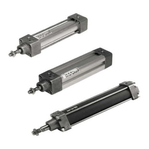
  9. Aventics TRB Series Setup guide

Aventics TRB Series Setup guide

The data specified above only serve to
describe the product. No statements
concerning a certain condition or suitability
for a certain application can be derived from
our information. The given information does
not release the user from the obligation of
own judgement and verification. It must be
remembered that our products are subject
to a natural process of wear and aging.
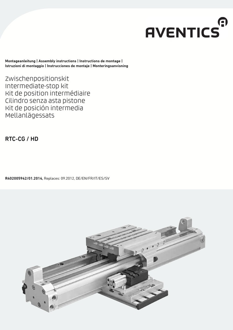
An example configuration is depicted on the
title page. The delivered product may thus
vary from that in the illustration.
Translation of the original operating
instructions. The original operating
instructions were created in the German
language.
R413001012–RAW–001–AA/12.2019
Subject to modifications. © All rights
reserved by AVENTICS GmbH, even and
especially in cases of proprietary rights
applications. It may not be reproduced or
given to third parties without its consent.
AVENTICS GmbH
Ulmer Straße 4
30880 Laatzen
Phone +49 (0) 5 11-21 36-949
Fax: +49 (0) 511-21 36-505
www.aventics.com
[email protected]
Further addresses:
www.aventics.com/contact
Reparaturanleitung | Repair instruction
FALTENBALG / ROD BELLOWS (RB)
ISO New Generation
Serie PRA/TRB
R413001012-RAW-001-AA/12.2019,
Replaces: 17.12.2019, DE/EN
AVENTICS | Serie PRA/TRB | 12.2019 1
1
Tabelle 1 / Table 1
Pos. / No. Beschreibung / Description Material / material *
10 FALTENBALG / BELLOWS NBR
25 GEWINDESTIFT / SET SCREW M4X5-A2 Metall / metal
28 O-RING / O-RING NBR
45 GEWINDESTIFT / SET SCREW M4X5-A4 Metall / metal
48** FILTER / FILTER D12 Sintermetall / sintered metal
49** ZACKENRING / TOOTHED RING Metall / metal
* Details finden Sie am Ende dieser Anleitung. / You will find details at the end of this description.
** Ab Ø 50 verbaut / Installed from Ø 50
Tabelle 2 / Table 2 - Stückliste / Bill of Material
R474000398 R474000399 R474000400 R474000401
2x (45)
3x (25)
4x (48)(49)
1x (28)
2x (10)
1x (28)**
4x (10)
1x (28)
4x (10)
** im Kit je Ø enthalten /included in the kit for each Ø
Durchmesser /
Diameter
Ersatzteilsatz /
Spare Part Kit
Stückliste /
Bill of Material
Ø 32-125 R474000398 Tabelle 2/ Table 2
Ø 32-40 R474000399 Tabelle 2/ Table 2
Ø 50-100 R474000400 Tabelle 2/ Table 2
Ø 125 R474000401 Tabelle 2/ Table 2
2AVENTICS| Serie PRA/TRB | 12.2019
1ZuIhrerSicherheit
Qualifikation des Personals
Montage, Demontage, Inbetriebnahme und Bedienung erfordern grundlegende mechanische,
elektrische und pneumatische Kenntnisse. Um die Betriebssicherheit zu gewährleisten,
dürfen diese Tätigkeiten daher nur von einer entsprechenden Fachkraft oder einer
unterwiesenen Person unter Leitung einer Fachkraft durchgeführt werden.
Eine Fachkraft ist, wer aufgrund seiner fachlichen Ausbildung, seiner Kenntnisse und
Erfahrungen sowie seiner Kenntnisse der einschlägigen Bestimmungen die ihm übertragenen
Arbeiten beurteilen, mögliche Gefahren erkennen und geeignete Sicherheitsmaßnahmen
treffen kann. Eine Fachkraft muss die einschlägigen fachspezifischen Regeln einhalten. Wenn
diese Information nicht beachtet wird, kann das zu Verschlechterungen im Betriebsablauf
führen.
Bei der Montage beachten
OSchalten Sie immer den relevanten Anlagenteil drucklos und spannungsfrei, bevor Sie
das Produkt montieren bzw. Stecker anschließen oder ziehen.
OSichern Sie den Anlagenteil gegen Wiedereinschalten.
OHängen Sie während der Montage Warnschilder an die Hauptschalter, die vor dem
Wiedereinschalten warnen.
2 Montageanweisung
1. Anlage drucklos und spannungsfrei schalten.
2. Demontieren Sie den Zylinder aus der Maschine. Lesen Sie hierzu die
Bedienungsanleitung des Maschinenherstellers.
3. Stellen Sie den Zylinder auf eine feste Unterlage.
4. Demontieren Sie den Zylinder gemäß Abbildung (Abb.1).
5. Lösen und entfernen Sie sämtliche Befestigungen vom Gewinde der Kolbenstange.
z.B.Mutter (003)
6. Schieben Sie den Balg (10) über die Frontscheibe (40).
7. Lösen und entfernen Sie die Gewindestifte (45+25) und ziehen die gesamte Balg-
Baugruppe (40,45,10,30,20,25,28) vom Zylinder herunter.
8. Ziehen Sie die Bälge (10) von der inneren Scheibe (30) und dem Haltering (20) herunter
und entfernen den O-Ring (28).
9. Pressen Sie nach Bedarf die Filter (48) mit den Zahnscheiben (49) aus der
Frontscheibe(40).
10. Reinigen Sie die Komponenten (40,30,20) mit Alkohol und nehmen sich das erworbene
Ersatzteil Kit zur Hand.
11. Entnehmen Sie die neuen Bälge (10) aus dem Kit und schneiden diese auf Länge zu. Als
Referenz können die zu ersetzenden Bälge oder die Zuschnitttabelle (Abb.2 / Tabelle3).
verwendet werden.
12. Setzen Sie den neuen O-Ring (28) in die Nut des Haltering (20) ein.
13. Ziehen Sie die Bälge (10) auf den Halteringe (20) und inneren Scheibe (30) auf.
ACHTUNG
Lesen Sie vor Montagearbeiten diese Anleitung gründlich und vollständig und befolgen
Sie die gegebenen Hinweise.
Beachten Sie auch die Anleitungen der übrigen Anlagen Komponenten. In dieser
Anleitung stehen Warnhinweise vor einer Handlungsanweisung, bei der die Gefahr von
Personen- oder Sachschäden besteht. Die beschriebenen Maßnahmen zur
Gefahrenabwehr müssen eingehalten werden.
WARNUNG
Verletzungsgefahr durch Montage unter Druck!
Wenn Sie den Druck vor Montagebeginn nicht abschalten, können Sie sich verletzen und
das Gerät oder Anlagenteile beschädigen.
OSchalten Sie den relevanten Anlagenteil drucklos, und spannungsfrei bevor Sie das
Produkt montieren.
VORSICHT
Beschädigung der Gewinde!
Die Gewinde der Schrauben, Gewindebohrungen etc. können beschädigt oder zerstört
werden.
OBenutzen Sie bei zur Montage ausschließlich einen Drehmomentschlüssel.
Montagehinweis:
Benutzen Sie zur De- und Montage der Dichtungen und Bälge ausschließlich ein
stumpfes Werkzeug.
Demontagehinweis:
Benutzen Sie zur Demontage des Balges (10) ein stumpfes Werkzeug.
Hinweis:
Anwendung nach Bedarf.
Eine Reinigung / Spülung der Filter (48) mit Alkohol könnte bereits ausreichen.
Montagehinweis:
Benutzen Sie zur Montage des Balges (10) ein stumpfes Werkzeug. Beachten Sie
den korrekten Sitz der Überlappung auf der inneren Scheibe (30) und den
überlappenden Bälgen (10).
1 FOR YOUR SAFETY!
Personnel Qualifications
Assembly, commissioning and operation, disassembly, service (including maintenance and
repair) require basic mechanical, electrical and pneumatic knowledge, as well as knowledge
of the appropriate technical terms. In order to ensure operating safety, these activities may
therefore only be carried out by qualified technical personnel or an instructed person under
the direction and supervision of qualified personnel.
Qualified personnel are those who can recognize possible hazards and institute the
appropriate safety measures due to their professional training, knowledge, and experience,
as well as their understanding of the relevant conditions pertaining to the work to be done.
Qualified personnel must observe the rules relevant to the subject area.
The following must be observed during assembly
OMake sure the relevant system component is not under pressure or voltage before
disassembling or reassemble the unit when connecting or disconnecting any hoses or
connectors.
OEnsure the system cannot be switched on accidentally.
OHang signs on the main switch that warn workers against switching the system on.
2 Assembly instruction
1. Depressurise the system and de-energize it.
2. Disassemble the cylinder from the machine. Read the operating instructions of the
machine manufacturer.
3. Place the cylinder on a firm surface.
4. Disassemble the cylinder as shown in the figure (fig.1).
5. Loosen and remove all fastenings from the thread of the piston rod. e.g. Nut (003)
6. Push the bellows (10) over the external disc (40).
7. Loosen and remove the set screws (45+25) and pull the bellows assembly
(40,45,10,30,20,25,28) from the cylinder.
8. Push the bellows (10) from the inner washer (30) and the retaining ring (20) and remove
the O-Ring (28).
9. Press the filter (48) with the tooth lock washers (49) out of the external disc (40) as
required.
10. Cleaning the parts (40,30,20) with alcohol and take the purchased parts of spare part
kit.
11. Take the new bellows (10) out of the kit and cut them to length. The bellows to be
replaced or the cutting table (fig.2 / Table3) can be used as a reference.
12. Put in the new O-Ring (28) in the slot of the holder ring (20).
13. Push the bellows (10) on the retaining ring (20) and inner disc (30).
14. Push the bellows assembly (10,30,20,25,28) onto the piston rod (002).
ATTENTION
Read these instructions completely before beginning of assembly.
Also follow the instructions for the other system components In this manual, there are
safety instructions before steps taken points to, whenever there is a danger of personal
injury or damage to the equipment. The measures described to avoid these hazards
must be observed.
WARNING
Risk of injuries when assembling under pressure!
If you do not switch off the pressure before assembling the product, you may get injured
or the device or system components may be damaged.
OAlways depressurize the relevant system component before disassembling /
assembling the product.
CAUTION
Check the threads for damage!
The threads could be damage during assembly.
OEnsure that mounting screws only have been tightened with a torque spanner.
Installation Note:
Use only a blunt tool to removal and assembling the seals and bellows.
Dismantling Note:
Use a blunt tool to disassemble the bellows (10).
Note:
Use as needed.
A cleaning / rinsing of the filter (48) with alcohol could already be sufficient.
Installation Note:
Use a blunt tool to mount the bellows (10) Make sure that the overlap fits correctly
on the inner disc (30) and the overlapping bellows (10).
DEUTSCH ENGLISH
AVENTICS | Serie PRA/TRB | 12.2019 3
14. Schieben Sie die Balg-Baugruppe (10,30,20,25,28) auf die Kolbenstange (002) auf.
15. Pressen Sie nach Bedarf den Filter (48) mit der Zahnscheibe (49) in die
Frontscheibe(40) ein und schieben diese auf die Kolbenstange (002) auf.
16. Justieren Sie die Frontscheibe (40) nach (Abb.2 / Tabelle 5) aus und ziehen
anschließend den Gewindestift (45) mit einem Drehmomentschlüssel 0,5 Nm (Abb.2 /
Tabelle 4) fest.
17. Schieben Sie die Balg-Baugruppe (10,30,20,25,28) über die Frontscheibe (40).
18. Schieben Sie die Balg-Baugruppe (10,30,20,25,28) soweit auf den Deckel, bis der
Haltering (20) am Deckel anschlägt.
19. Ziehen Sie die Gewindestifte (25) mit einem Drehmomentschlüssel 0,5 Nm (Abb.2 /
Tabelle 4) fest und montieren nach Bedarf die zuvor demontierten Befestigungen z.B.
Mutter (003) mit der Kolbenstange (002).
20. Montieren Sie den Zylinder wieder in Ihre Maschine. Lesen Sie hierzu die
Bedienungsanleitung des Maschinenherstellers.
OEntsorgen Sie nicht mehr benötigte Teile nach den Bestimmungen Ihres
Verwenderlandes.
Materialbezeichnungen entnehmen Sie der Tabelle.
Montagehinweis:
Benutzen Sie zur Montage des Balges (10) ein stumpfes Werkzeug. Beachten Sie
den korrekten Sitz der Überlappung auf der Frontscheibe (40).
Montagehinweis:
Wenn die Kolbenstange (002) etwas eingefahren ist, lässt sich die Balg-
Baugruppe(10,30,20,25,28) besser Montieren.
Beachten Sie die Einbaulage des Halteringes (20) bei Zylindern Ø32. Richten Sie
die Aussparungen passend zu den Schrauben des Zylinders aus.
Material Bezeichnung
NBR Acrylnitril-Butadien-Kautschuk
15. Press as needed the filter (48) with the tooth lock washers (49) in to the front disc (40)
and slide these on the piston rod (002).
16. Adjust the front disc (40) according to (fig.2 / Table 5) and then tighten the set
screw(45) with a torqe wrench 0,5 Nm (fig.2 / Table 4).
17. Slide the bellows assembly (10,30,20,25,28) over the front disc (40).
18. Push the bellows assembly (10,30,20,25,28) onto the cover until the retaining ring (20)
strikes the cover.
19. Tighten the set screws (25) with a torque wrench 0,5 Nm (fig.2 / Table 4) and assemble
the previously dismantled fastenings as required, e.g. Nut (003) with the piston rod
(002).
20. Mount the cylinder back into your machine. Read the operating instructions of the
machine manufacturer
ODispose the old parts in accordance with current applicable national regulations of your
country.
Material description can be found in the table below.
Installation Note:
Use a blunt tool to mount the bellows (10). Make sure that the overlap is correctly
seated on the front disc (40).
Installation Note:
If the piston rod (002) is slightly retracted, the bellows assembly (10,30,20,25,28)
is easier to assemble.
material description
NBR Acrylnitril-Butadiene-Rubber
DEUTSCH ENGLISH
2
Tabelle 3/ Table 3 - Anzahl der Falten pro Hub / Number of folds per Stroke
Tabelle 4/ Table 4
Ø32 Hub/Stroke 0-75 76-150 151-250
Falten/Folds 9 all 10
Ø40 Hub/Stroke 0-125 126-250 251-350 351-500
Falten/Folds all 10
Ø50-80 Hub/Stroke 0-130 131-250 251-500 501-630 631-750 751-1000
Falten/Folds 11/8 11/10/11 11/10/10/10/11 11/10/10/10/10/10/11
Ø100 Hub/Stroke 0-125 126-250 251-500 501-600 601-750 751-1000
Falten/Folds 8/6 8/7 11/10/11 11/10/10/11 11/10/10/10/6 11/10/10/10/10/11
Ø125 all 10
Anzugsmoment
Tightening Torque
Ø Pos. 25 Pos. 45
32-125 0,5 0,5
Tabelle 5/ Table 5
AF
+/- 0,5
F
+/- 0,5
Ø32 34 12
Ø40 39 15
Ø50 47 15
Ø63 47 15
Ø80 57 17
Ø100 57 17
Ø125 71 17

Other manuals for TRB Series

2

This manual suits for next models

1

Other Aventics Industrial Equipment manuals

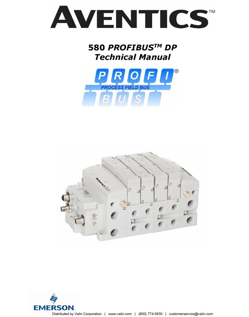
Aventics 580 PROFIBUS DP User manual

Aventics

Aventics 580 PROFIBUS DP User manual

Aventics GPC User manual

Aventics

Aventics GPC User manual

Aventics LU6 User manual

Aventics

Aventics LU6 User manual

Aventics 5217 Series Setup guide

Aventics

Aventics 5217 Series Setup guide

Aventics DDL-X-Tool User manual

Aventics

Aventics DDL-X-Tool User manual

Aventics EBS-PT -VE Series User manual

Aventics

Aventics EBS-PT -VE Series User manual

Aventics R434001024 Operating and installation instructions

Aventics

Aventics R434001024 Operating and installation instructions

Aventics TRB Series Setup guide

Aventics

Aventics TRB Series Setup guide

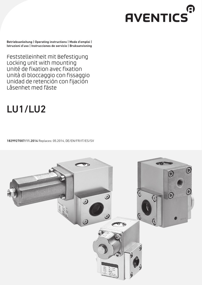
Aventics LU1 User manual

Aventics

Aventics LU1 User manual

Aventics 580 PROFINET User manual

Aventics

Aventics 580 PROFINET User manual

Aventics Emerson AS5-ACD Series Installation instructions

Aventics

Aventics Emerson AS5-ACD Series Installation instructions

Aventics CANopen 580 Series User manual

Aventics

Aventics CANopen 580 Series User manual

Aventics TC08 User manual

Aventics

Aventics TC08 User manual

Aventics PM1 User manual

Aventics

Aventics PM1 User manual

Aventics R434001025 User manual

Aventics

Aventics R434001025 User manual

Aventics R434004984 Operating and installation instructions

Aventics

Aventics R434004984 Operating and installation instructions

Aventics RTC-CG User manual

Aventics

Aventics RTC-CG User manual

Aventics 580 Series User manual

Aventics

Aventics 580 Series User manual

Aventics 580 CHARM User manual

Aventics

Aventics 580 CHARM User manual

Aventics EBS-PT User manual

Aventics

Aventics EBS-PT User manual

Aventics MSC Series User manual

Aventics

Aventics MSC Series User manual

Aventics ECD-BV User manual

Aventics

Aventics ECD-BV User manual

Aventics MSC User manual

Aventics

Aventics MSC User manual

Aventics Powerlink 580 User manual

Aventics

Aventics Powerlink 580 User manual

Popular Industrial Equipment manuals by other brands

Envirotainer RKN t2 Operation manual

Envirotainer

Envirotainer RKN t2 Operation manual

THORLABS Vytran LFS4100 user guide

THORLABS

THORLABS Vytran LFS4100 user guide

Alfa Network Alfa-V VDD instruction manual

Alfa Network

Alfa Network Alfa-V VDD instruction manual

Van Beest Green Pin instruction manual

Van Beest

Van Beest Green Pin instruction manual

ABB HT613217 Operation manual

ABB

ABB HT613217 Operation manual

Rondo Manomat operating manual

Rondo

Rondo Manomat operating manual

SMW Autoblok SLX e-motion instruction manual

SMW Autoblok

SMW Autoblok SLX e-motion instruction manual

Phoenix Contact UM EN FLX ASI SYS PRO INST user manual

Phoenix Contact

Phoenix Contact UM EN FLX ASI SYS PRO INST user manual

DENTAURUM 072-001-00 Instructions for use

DENTAURUM

DENTAURUM 072-001-00 Instructions for use

Scheppach hf 50 Translation from the original instruction manual

Scheppach

Scheppach hf 50 Translation from the original instruction manual

Stahl 8579/2 Series Installation operation & maintenance data

Stahl

Stahl 8579/2 Series Installation operation & maintenance data

SCHUNK ELM Series Assembly and operating manual

SCHUNK

SCHUNK ELM Series Assembly and operating manual

MAGSTIM RAPID2 operating manual

MAGSTIM

MAGSTIM RAPID2 operating manual

Rohde AB100 instruction manual

Rohde

Rohde AB100 instruction manual

Nordson DuraBlue D4L Customer product manual

Nordson

Nordson DuraBlue D4L Customer product manual

Regal Morse M Series Installation and maintenance instructions

Regal

Regal Morse M Series Installation and maintenance instructions

Jct JES-360Ex operating manual

Jct

Jct JES-360Ex operating manual

schmersal AZM300B-I2-ST-SD2P-A-T Instructions for operation

schmersal

schmersal AZM300B-I2-ST-SD2P-A-T Instructions for operation

manuals.online logo
manuals.online logoBrands
  • About & Mission
  • Contact us
  • Privacy Policy
  • Terms and Conditions

Copyright 2025 Manuals.Online. All Rights Reserved.