Aventura TS-FBS01 User manual

INSTALLATION MANUAL
FOR
TS-FBS01 FLAP BARRIER TURNSTILES
Revision
Date
Description
Initials
0
2017-07-02
New template
LR
1
2018-05-12
Manual update
KN
---
---
---
---

Page 2of 8
Index
Chapter 1 –INTRODUCTION .........................................................................................................................3
1.1. Product features ................................................................................................................................3
1.2. Product specifications........................................................................................................................3
1.3. Product dimensions ...........................................................................................................................4
Chapter 2 –INSTALLATION ...........................................................................................................................7
Chapter 3 –TROUBLESHOOTING AND SUPPORT..........................................................................................8

Page 3of 8
Chapter 1 –INTRODUCTION
This manual will address dimensions and the features of the TS-FBS01 turnstile while also
covering the process in which this turnstile is installed.
1.1. Product features
The TS-FBS01 flap barrier turnstiles have the following features:
-Material: standard 304 stainless steel, with the option of getting 316 stainless
steel, and acrylic flaps.
-Customized flap etching and color, reader cut-out, or barcode reader insert.
1.2. Product specifications
The TS-FBS01 flap barrier turnstiles have the following characteristics:
-Power requirements: 110Vac [220Vac], 250W to 500W. The flap barrier turnstiles
are provided with different power supplies, based on country and customer’s
requirements. Check the product label before connecting to any power supply.
-Driver motor: 24Vdc, max. 40W
-Output interface: 12Vdc
-Communication interface: RS485
-Operating temperature: 14°F to 122°F [-10°C to 50°C]
-Operating humidity: 20% to 95% RH non-condensing

Page 4of 8
1.3. Product dimensions
Top View Single Movement
Front View Single Movement

Page 5of 8
Top View Double Movement
Front View Double Movement

Page 6of 8
Side View
Two Lane Layout

Page 7of 8
Chapter 2 –INSTALLATION
Before proceeding to the installation of the turnstile, unpack all components and check
to make sure the all parts from the packing slip are included, verify dimensions and conduit runs.
Use the turnstile template to properly align and lay out the site and to determine the right
location of the floor stub-ups and anchors.
Site preparation:
-Make sure that the floor is level before the installation process starts.
-When measuring the distance between the cabinets always refer to the center of
the cabinets, not the corners.
-Using the factory provided template and design layout drawings outline the exact
position of each turnstile. Make sure the floor outline includes the space
dedicated to conduit stub-ups.
-Install conduits for low voltage cables and for 110Vac (220Vac) power. Size
conduits based on the number of cables and follow local installation codes.
-Install one ¾ inch conduit for turnstile communication between two cabinets that
form one lane.
-Depending on the position, each enclosure can host one or two motors. The end
cabinets have only one motor (SM series) and the middle cabinets have two
motors (DM series).
-Each controller operates one motor. SM series have one controller and DM series
have two controllers.
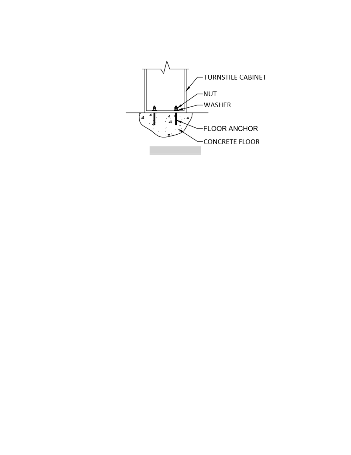
-On the turnstile floor footprint, locate anchoring holes. Drill and install foundation
screw bolts or M12 anchor bolts.
-Align and install the turnstile cabinet on the anchor bolts. Secure the cabinet to
the bolts.
-Follow wiring diagram to terminate the cables on the turnstile control panel. The
following connections are required:
oCard reader to control panel reader port. The control panel can be located
inside the turnstile or outside.
oCommunication cable between cabinets.
oLane OPEN command from the turnstile to the access control panel door
open relay.
oIf required, an emergency open button or switch can be wired to the
turnstile controller board.
o110Vac (220Vac) is required for each turnstile cabinet.

Page 8of 8
-For physical installation setup refer to the next drawing.
Installation Design
Chapter 3 –TROUBLESHOOTING AND SUPPORT
For Troubleshooting and Support, please contact Aventura Technologies Inc.:
Tel: +1.631.300.4000
Fax: +1.631.434.7000
Skype: aventurasupport
Website: http://www.aventurasecurity.com
Table of contents
Other Aventura Turnstile manuals