AVer VC520 Pro User manual

VC520 Pro MS Conference Camera
Quick Installation Guide
Package Contents
Camera Unit Speakerphone Unit Remote Control &
AAA Batteries
Power Adapter &
Power Cord*
USB 3.0 Cable Speakerphone
Cable (Blue)
3.5 mm Audio
Cable
L-Mount
Brackets
Screws for
Mount
Drilling Paper
Quick
Installation
Guide
Warranty Card Two Expansion
Microphones
Two
Extension Mic
Cables (Y/R)
P/N: 303AU 340-AGR
46.00[1.81]
51.00[2.01]
Ø5.50[Ø0.22]
MICINMICOUT
MICINMIC OUT
*The power cord will vary depending on the standard power outlet of the country where it is sold.
More Help
For FAQs, technical support, software and user manual download, please visit
Global & European Headquarters: https://www.aver.com/download-center
USA: https://www.averusa.com/business/support/

Overview
1
2 3 4 5 6 7 8
1
Status LED
5
RS232 in/out port
2
IR sensor
6
Ethernet port
3 Speakerphone port
(Blue cable)
7
8
DC 12V power jack
Kensington Lock
4 USB3.1 Type B port
91011 12 13
9 Speakerphone port
(For extended speakerphone
and microphone connection/
Red cable)
10
11
12
13
Phone in port
Line out port
Camera port (Blue cable)
Kensington Lock
MIC INMIC OUT
14 15
14 Microphone out port
(For extended microphone
connection/ Yellow cable)
15 Microphone in port
(For extended microphone
connection/ Red cable)

Installation
1.
Connect the camera to power outlet.
Power cord
Power adapter
2.
Connect the camera to the
speakerphone using the included
compatible cable.
[Note]
Both speakerphone and camera ports are
marked in blue.
The back cover of the speakerphone will
need to be removed to connect the
speakerphone cable.
Speakerphone
cable
3.
Connect the microphone to the
speakerphone.
[Note
] Use the microphone cables that are
included in package (Connect
Red cable to Red
connector. Connect
Yellow cable to Yellow
connector.).
Microphone cables
MICINMICOUT
MICINMIC OUT
4.
Connect the camera to the
computer/Laptop.
[Note]
Use the USB 3.0 cable that is included in
package.
USB cable

5.
Connect other necessary cables.
[Note]
USB and RS232 cable need to secure the
cable with attached screw. RS232 cable is
an optional accessory; pleas
e purchase
from the AVer.
Make sure the cable is well connected to the
connector on the camera before securing
the cable.
Important Notice For Microsoft Teams Room Solutions
The following physical ports will be disabled when initiating Microsoft Teams Room software on the
VC520 Pro: RS232, Ethernet. While connecting the VC520 Pro to a Microsoft Teams Room System,
the camera will automatically upgrade to the newest FW from Microsoft’s Windows Update Services.
The new firmware of 0.0.1004.35 and later will follow Microsoft’s Teams Room Policy to disable the
I/O ports. If you are not using Microsoft Teams Room software, the ports will not be disabled.
To enable the physical ports while using Microsoft Teams Room solutions, please download AVer’s
latest PTZApp to adjust the settings. Should you have any further questions, please contact AVer’s
Technical Support Team.
Install the Microsoft Teams client on your PC. After connecting the Teams client, tap the Teams
button to invoke the Teams client.
Teams Button LED Indicator
LED Indicator
Description
Slow flashing white Received missed calls/voice mails/Teams meeting start notification
indicators
Solid white Teams connected
Off Teams disconnected

Remote Control
Camera Select
Camera Directional
Control
OSD Menu**
SmartFrame
Zoom In/Out
Preset
Call/Answer*
Brightness -
Enter**
Mute/Un-mute
Volume Up/Down
Preset Hot Key
Preset Position
Hang Up*
Brightness +
*Function requires AVer PTZApp
**Not supported for VC520 Pro
Camera Select:If you only have one camera and
don’t need to adjust custom settings, the default is
camera 1. If you press camera 2 or 3 on the
remote control, you will find your remote can’t
control your camera. In this case, please press
camera 1 on your remote again.
SmartFrame:Press and hold for 1 second
to switch the SmartFrame function between auto
and manual modes. A message (as figure shown)
will display on the screen to indicate auto or
manual mode.
[Note] While in a conference call, participants
must face the camera for proper face
detection. Side facial profiles are not
detectable. Please refer to the user’s manual for
more details.
Press and hold the number 1() to turn the
WDR function on or off.
AAA Batteries (required).
Wall Mount Installation
12 3
45
6
B
A
A
P/N: 303AU340- AGR
46.00[1.81]
51.00[2.01]
Ø5.50[Ø0.22]
1. Use the drilling paper included in the
package to drill the holes in the wall
where the user wants to mount the
camera.
2. Use the screw to secure the
A
L-mount bracket on the wall.
3. Then, assemble the
A
+
B
L-mount
bracket with screws (included in
package).
4. After assembling the L-mount bracket,
secure the lower part of L-mount bracket
on the wall.
5. Connect cables to the corresponding
connection ports and pass the cables
through the hole on the L-mount bracket.
6. Use the screws (included in package) to
secure the cameras on the L-mount
bracket.

Making a Video Call
A computer is required to use this device.
1. Open your video collaboration application such as Zoom, Microsoft®Teams, Skype for Business,
Skype, Google Hangouts, Intel® Unite™, RingCentral, BlueJeans, V-Cube, LiveOn, CyberLink U
Meeting®, TrueConf, Adobe Connect, Cisco WebEx®, Fuze, GoToMeeting™, Microsoft®Lync™,
Vidyo, vMix, WebRTC, Wirecast, XSplit.
2. Set the VC520 Pro as your primary camera device in your application (Please consult your
application setup guide for details).
3. Ready to make a video call.
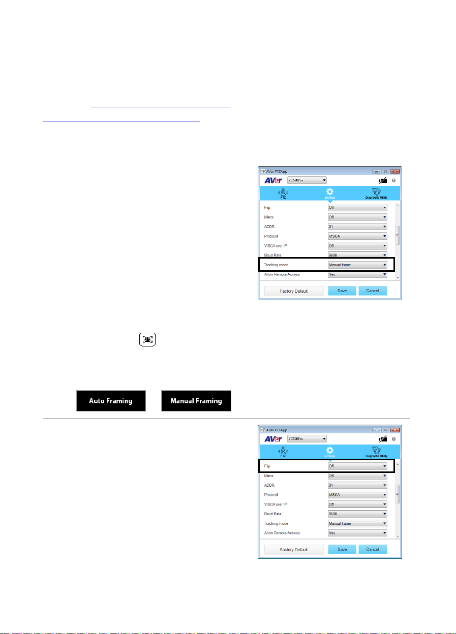
[Note] VC520 Pro is a plug-n-play conference camera. The system requires no special drivers. For
advanced setting and firmware update, please download AVe r P T ZAp p .
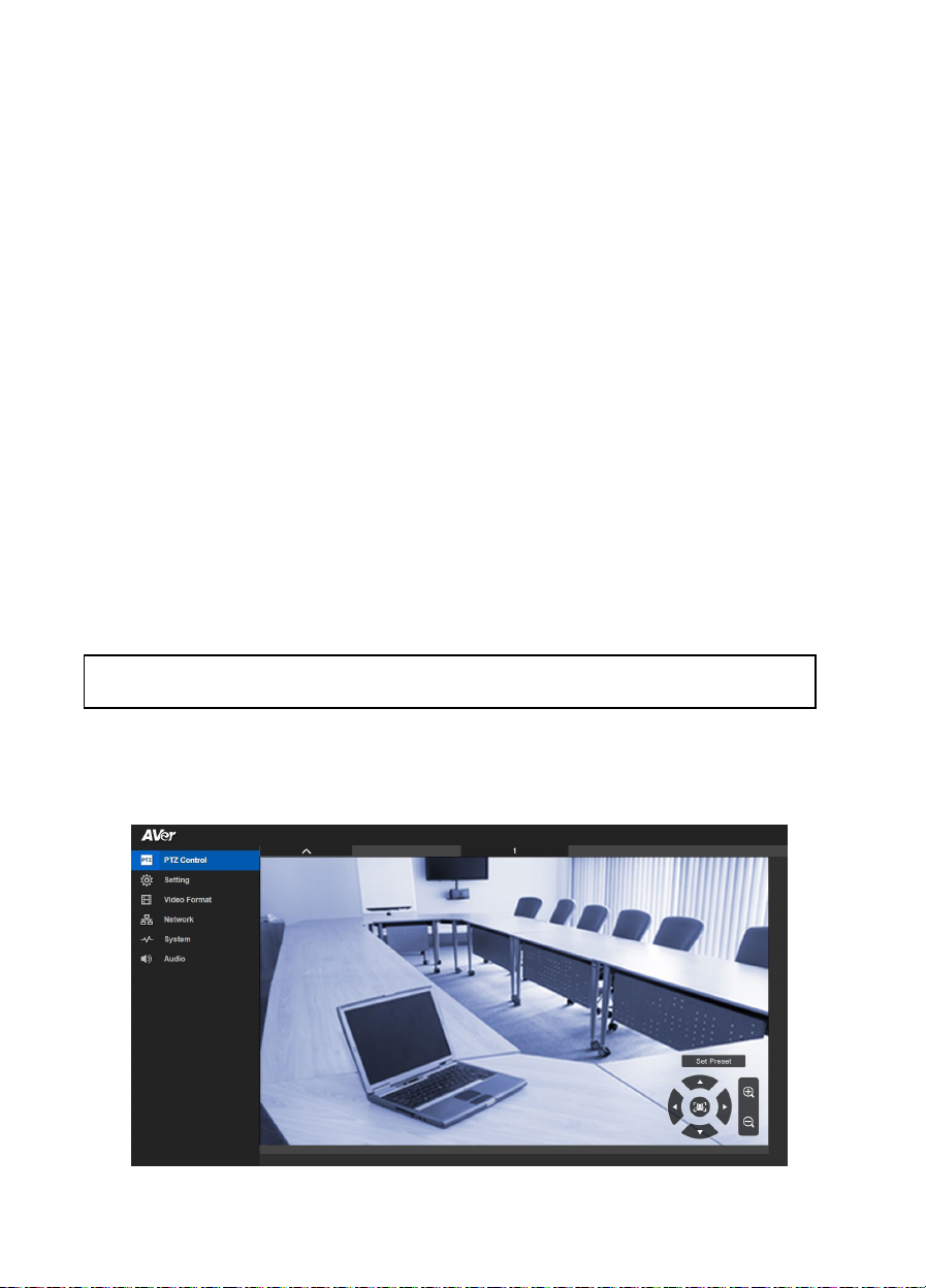
Setting up the Camera through the Web Browser
VC520 Pro has an Ethernet port for IP streaming and allows administrators to remotely control and set
up the camera via an internet access. Moreover, VC520 Pro also supports RTSP and RTMP functions.
For further details, please refer to user’s manual or contact our technical support.
1. Make sure the VC520 Pro has an internet access connection.
2. Open the browser and enter the IP address of the camera.
[Note] The browser supports:
Chrome: version 76.x or above Firefox: version 69 or above IE: Doesn’t support
The camera default IP address is 192.168.1.168. User can use “AVer IP Finder” app to find the
camera (Please refer to “Using AVer IP Finder to Find the Camera” section).
3. When login screen is shown, enter the password (default password is aver4321).
4. The web main screen is displayed.

Using AVer IP Finder to find the Camera
To find the IP address of your cameras, you can use the AVer IP Finder application. Follow the below
steps to find the IP address of camera.
Download the IP Finder from https://www.aver.com/download-center (Global & European
Headquarters) or https://www.averusa.com/business/support/ (USA).
1. Run the IP Finder.
2. Click “Search”, and all available devices will be listed on the screen.
3. Select a camera from the list. The corresponding fields of IP address will display.
4. To change the IP address of camera, select “DHCP” or “Static IP”.
The DHCP should get the IP address from local dynamic IP sever. The static IP, user can enter the
specific IP address. Click “Apply” to apply the setting to the camera. The login password is
required (default password is aver4321; same as web access password).
5. Click “Search” button to re-scan the camera.
6. Double-click on the IP address of camera from the list can connect to camera through the browser.
[Note] If IP Finder cannot find the camera, please check following:
Please make sure the Ethernet connection of camera is well connected.
The camera and PC (IP Finder) are in the same LAN segment.

Installing AVer PTZApp
In AVer PTZApp, user can configure the parameters of the camera.
Please go to https://www.aver.com/download-center (Global & European Headquarters) or
https://www.averusa.com/business/support/ (USA) to download the AVer PTZApp. After downloading,
double-click on the file and follow the on-screen instructions to complete the installation.
Using AVer PTZApp
1. After installing the AVer PTZApp, double-click on the
AVer PTZApp icon to run the application.
2. During your video call, you can use the AVer
PTZApp to pan, tilt and zoom the camera in/out and
enable/disable the backlight feature, set up camera
Home or Sleep mode preset points. For more
details, please refer to the user manual.
3. Tracking mode: It is a SmartFrame function which
can auto detect faces of people to find the best view
for all meeting participants. Users can change
SmartFrame function status in AVer PTZApp. In
AVer PTZApp, select “Settings” > “Tracking mode”
> “Auto frame/Manual frame/off”.
Also, Press and hold on the remote for 2
seconds to switch the SmartFraming function
between auto and manual mode; a message (as
figure shown) will display on the screen to indicate
auto or manual mode.
[Note] While in the video conference
meeting, participants must face the
camera for proper face detection
(SmartFrame). Side facial profiles are
not detectable.
4. Flip: If the camera is installed in the upside down
position, please enable the "Flip" function in the
AVer PTZApp, and the screen will display normally.

5. Hotkey Control: Enable hotkey control to use keyboard control camera’s movement and
backlight. The default is off.
A hotkey tip will display when mouse is moved to the PTZ control
button in PTZ mode.
If the hotkey function is enabled after installing the PTZApp,
PTZApp auto launch next time the PC reboots. Therefore, the
customer can use all the hotkey commands when PTZApp is
auto running in system tray.
6. Speakerphone: setup speakerphone function
parameters.
- Nosie suppression: Reduce ambient noise.
- Automatically gain control: Enable/disable the
auto gain control.
- Echo cancellation: Enable/disable echo
situation.
- Keyboard noise suppression: Enable/disable
keyboard noise reduction.
- Phone in jack
Phone in: When the mobile phone is
connecting to Phone in port, please select
“Phone in” option.
3.5 mm microphone only: The speakerphone will transfer the sound
that it receives
from the external microphone (connected on phone in port) to far site.
3.5 mm microphone mix in: The speakerphone will transfer the sound that it receives
from the external microphone (connected on phone in port) and speakerphone to far site.

Contact Information
Global
AVer Information Inc.
https://www.aver.com
8F, No.157, Da-An Rd.,
Tucheng Dist.,
New Taipei City 23673,
Taiwan
Tel: +886 (2) 2269 8535
USA
AVer Information Inc.
https://www.averusa.com
668 Mission Ct.,
Fremont, CA 94539
Tel: +1 (408) 263 3828
Toll-free: +1 (877) 528 7824
Technical support:
support.usa@aver.com
European Headquarters
AVer Information Europe B.V.
https://www.avereurope.com
Westblaak 140, 3012KM,
Rotterdam, Netherlands
Tel: +31 (0) 10 7600 550
Technical support:
eu.rma@aver.com
Federal Communication Commission Interference Statement
NOTE: This equipment has been tested and found to comply with the limits for a Class A digital device, pursuant to
part 15 of the FCC Rules. These limits are designed to pro-vide reasonable protection against harmful interference
when the equipment is operate din a commercial environment. This equipment generates, uses, and can radiate
radiofrequency energy and, if not installed and used in accordance with the instruction manual, may cause harmful
interference to radio communications. Operation of this equipment in a residential area is likely to cause harmful
interference in which case the user will be required to correct the interference at his own expense.
FCC Caution: Any changes or modifications not expressly approved by the party responsible for compliance could
void the user's authority to operate this equipment.
This device complies with part 15 of the FCC Rules.
Operation is subject to the following two conditions:
(1) This device may not cause harmful interference, and
(2) this device must accept any interference received, including interference that may cause undesired operation.
Warning:
This is a class A product. In a domestic environment this product may cause radio interference in which case the
user may be required to take adequate measures.
CAUTION
- Risk of explosion if battery is replaced by an incorrect type.
- Dispose of used batteries in a safe and proper manner.
©2021 AVer Information Inc. All rights reserved.
V1
Other manuals for VC520 Pro
4
Table of contents
Other AVer IP Camera manuals
Popular IP Camera manuals by other brands

Dahua
Dahua DH-HAC-HFW1100RP-VF user manual

Ganz
Ganz PixelPro GXi Series ZN1-D4NMZ43L installation guide

TRENDnet
TRENDnet TV-IP600W - Wireless Pan/Tilt/Zoom Internet Camera Server... Specifications

Vicon
Vicon XX235-10-00 Installation and operation guide

Pelca
Pelca Spectra Professional series user manual

3rd Eye
3rd Eye TE93 instructions