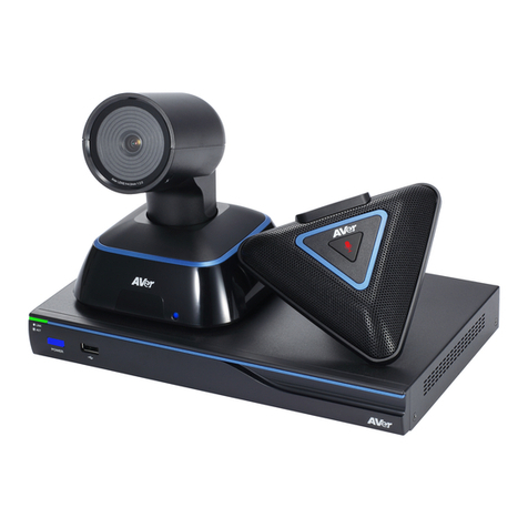
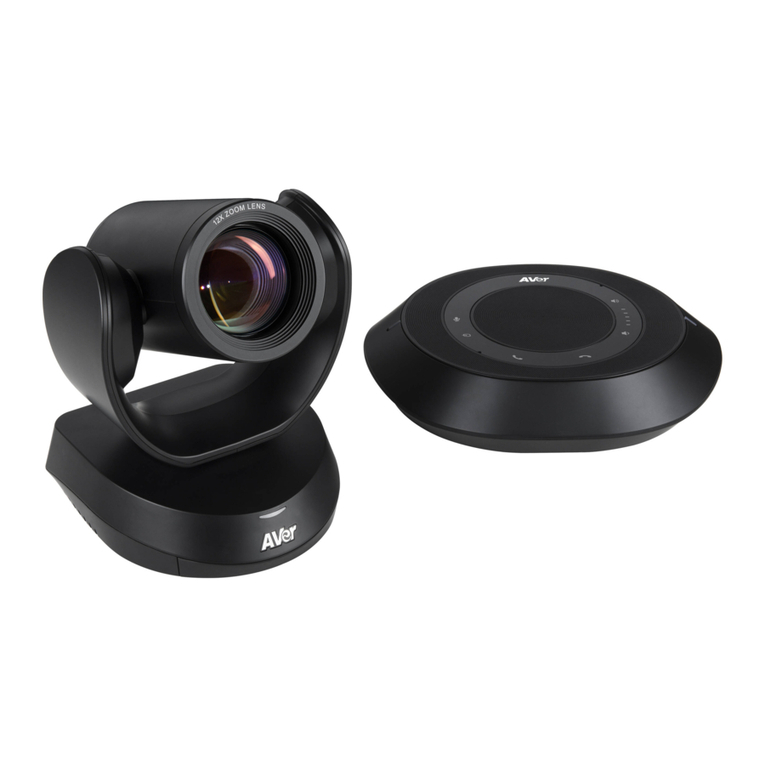
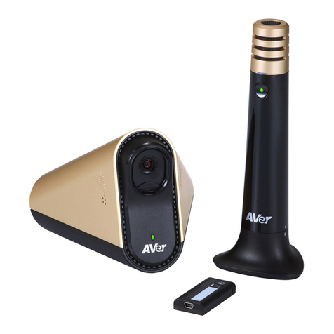
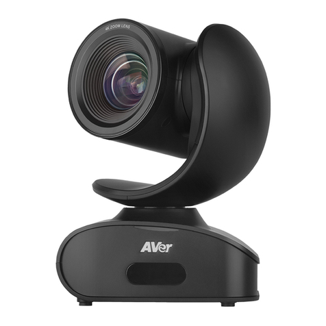
AVer VC520 User manual

VC520
User Manual
English
Deutsch
Español
Français
Italiano

English
English-1
Package Contents
1
2
3
4
5
6
7
8
9
10
11
12
13
1. Camera
2. Hub
3. Speakerphone
4. Remote Controller
5. Mount (mounting screws are included)
6. Power Cord1& Power adapter
7. Velcro for hub2
8. USB cable
9. Camera cable
10. Speakerphone cable
11. 3.5mm AUX cable
12. Quick Installation Guide
13. AAA Batteries (x2)
[Note] 1. The power cord will vary depending on the standard power outlet of the country where it is sold.
2. Adhesive fastener holds the hub when mounted under your flat surface. Use appropriate cleaning solution when removing the fastener. Test the
cleaning solution to make sure that it will not damage the surface.
Product Introduction
Camera
6
123 4 5
1. IR Sensor
2. Power indictor
3. Hub connection
4. RS232 connection*
5. Kensington lock
6. Screw hole for mounting
* If you need a converter or instructions on how to use RS232,please contact AVer.

English-2
Speakerphone
1
2
3
4 5 6 7 8
1. Cellphone indicator
2. Volume up/down
3. Mute/unmute speakerphone*
4. Speakerphone(daisy chain)
5. Hub connection
6. Kensington lock
7. Line out
8. Phone in
* Red LED: speakerphone is on mute
* Blue LED: speakerphone is active (or live)
Hub
1 2 3 4
Remote Controller
9
2
1
8
7
6
5
3
4
* Function requires AVer PTZ
app
Name
Function
1. Mute/Unmute Speakerphone
Mute/Unmute the speakerphone.
2. Zoom in/Zoom out
Increase/Decrease the camera zoom.
3. Call/answer*
Answer a call or starta call.
4. Preset
Press to get back to “home”position that user has set.
Move camera to desired position. Press and hold the preset button until saved
message is displayed on screen. Select preset position button 0~9 to save
current camera position. Press preset + preset position button (0~9), camera
will go to saved position.
5. Preset position
Press preset + preset position button (0~9), camera will go to saved position.
6. Far site camera control
Press the Far/Near button to control the far site camera for pan, tilt, or zoom
functions.
7. Camera direction control
Use the direction button on the remote to control the direction of the camera. Press
the direction button to move the camera or press and hold for continuous pan or tilt.
8. Hang up*
End the call.
9. Volume up/down
Adjust volume up or down.
1. Power jack
2. USB port
3. Speakerphone connection
4. Camera connection

English-3
Setup VC520
Device Connection
DC 12V
Camera cable Speakerphone cable
Power cable
Wall outlet
Camera
Hub Speakerphone
USB cable
Laptop PC
Mounting Camera
There are 3 ways to mount the camera –on the wall, on the ceiling, and on a table with the mount and screws included in the package.
[Warning]
1. When securing the camera mount on a wall or celling, only use hardware and materials certified to support 22 lb (10 kg) weight. For dry wall installation,
please use Sleeve-Type Hollow Wall Anchors (a.k.a. Molly Bolts).
2. If the camera mount is secured to a table, please note excessive table movement or pulling on the camera cables may cause the mount and camera to
fall. Ensure the cables and camera are secured properly.
Wall
Ceiling
1. Use the camera cable and the speakerphone cable to
connect the camera, hub, and speakerphone (refer to
diagram above).
2. Use USB cable to connect the hub to your PC/laptop
(refer to diagram above).
3. Connect the power to the hub; LED will light up,
camera head will rotate, and the camera power
indictor will light up.
4. InstallAVer PTZ app on laptop or PC that is connected
with VC520. The app can be used to adjust and
setup the parameters of the camera (refer to section of
AVer PTZ app)
5. To make a call, run your video application (SkypeTM,
Microsoft ®LyncTM, Google HangoutsTM, Cisco
WebEx®, GoToMeetingTM, WebRTC, and etc.), select
VC520 as your video and audio device.

English-4
Table
Use VC520
Make a Video Call
1. Make sure all devices (camera, hub, speakerphone, and laptop/PC) are well connected and hub is powered on.
2. Run your video application (SkypeTM, Microsoft ®LyncTM, Google Hangout, Cisco WebEx®, GoToMeetingTM, WebRTC, and etc.) on your laptop or PC.
3. Set the VC520 camera as the primary camera for your video application (refer to your video application user guide). You can now make your call.
4. The VC520 is a plug-and-play conference camera. The system requires no special drivers, but we do recommend installing theAVer PTZ app for a better
user experience.For information on how to install and use theAVer PTZ app, refer to the AVer PTZ App section in this user manual.
Phone in
To connect the VC520 speakerphone to your mobile phone as a hands free call device.
1. Use the included 3.5mm AUX cable to connect your mobile device to the “Phone In” jack on the speakerphone.
2. Once the VC520 detects the proper connection to your mobile phone, When connection is successful, the “Cellphone”indicator will light up.
Line in
To connect another VC520 speakerphone to extend the distance of speakerphone coverage to cover a room that has a diameter larger than 30’ and increase
the volume:
1. Connect one side of the daisy chain cable (not included) to the speakerphone port (daisy chain).
2. Connect the other side of the cable to the speakerphone port on the other VC520 speakerphone.
LED Indicator
Camera
Status
LED
Starting
Flashing blue and camera head is rotating
Normal
Solid blue
Camera is not being used by the computer
Solid orange
Camera is not connected
Solid orange and camera head is down.
Speakerphone( )
Cellphone( )
Status
LED
Mute
Solid Red
Unmute
Solid blue
Status
LED
Connect
Light on
Disconnect
Light off

English-5
a
c
b
d
e
f
g
AVer PTZ App
Install AVer PTZ App
Please go to http://www.aver.com > Support > Download Center > Video Conferencing to download the AVer PTZ app.After downloading, double-click on
the file and follow the on screen instructions to complete the installation.
Remember to select the “Skype plug-in”option during installation.
After installing theAVer PTZ app, double-click on the AVer PTZ app icon to run the application.
Use AVer PTZ App
1. To run you video application, a plug-in request will be displayed on your video application
interface. Click on it to accept the plug-in; your video application can now be control by AVer
PTZ app and remote control.
If you have the Skype plug-in checked during the installation, a plug-in request will be displayed
in Skype. Click on the Skype plug-in request to accept the plug-in; this enables and
funcationality on the Remote Control.
2. During your video call, you can use the AVer PTZ app to pan, tilt and zoom the camera in/out
and enable/disable the backlight feature.
3. For the first time use, you can check the connection, camera, and speaker status, and setup
the camera’s parameters. Each function will be described below:
a. Function icon: Click it to switch to the function’s page
- PTZ: To control the camera direction, zoom in and out, and to enable/disable the backlight compensation
during your video call.
- Settings: To setup parameters of the camera –White balance, noise filter, frequency, brightness,
sharpness, flip, mirror, ADDR, and baud rate. ADDR and baud rate is for RS232 connection setting. Click
the Save button to save all settings. To change all the settings, back to the default values, click the
Factory Default button.
- Diagnostic Utility: To display the S/W and F/W version and the devices connection status. You can also
test the camera and speakerphone status, and update the firmware of the camera.
English-6
b. Minimize: Minimize the app to system tray. To quit the application,
right-click the icon on the system tray and select “Quit”.
c. / (Camera): Click it to
view the camera live view. Click the
camera icon again to close the
camera live view. If the live video did
not appear, please check the camera,
hub, and the laptop/PC connection to
make sure all are correct and well
connected.
d. Connection diagnostic: Display devices connection status. If the AVer PTZ app has detected that some
of the devices (camera, speakerphone, hub, and laptop/PC) are not connected well, the diagram will
display an “X”on the device to indicate the connection has a problem. If the camera is in use by another
application, it will display “Can’t start video” warning.
e. Test Camera: Click the “Test Camera” button to check the camera video display status. You can adjust the camera direction and view of the zoom
in/out. To leave the page, click the Abort Diagnostic button.
f. Test Speakerphone: Click to check the speakerphone status. It will require the user to record a short message and play it back to ensure the
speakerphone is working.
g. Update Now: Allows the user to update the VC520 camera’s firmware.
1. Click” Update Now”.
2. A dialog will display the current firmware version and available new firmware version (internet connection is required).
3. To auto update, click “Auto Update”and update process will start. The new firmware will be downloaded first; then, the new firmware will be uploaded
to camera.
[Note] Before updating the new firmware to the camera, please make sure camera, hub, and laptop/PC are all well connected and stay connected
during the entire process.
4. To update the firmware manually, click “Manual Update”and locate the new firmware to start the process.
© 2015 AVer Information Inc. All rights reserved.

Deutsch
Deutsch-1
Inhalt der Verpackung
1
2
3
4
5
6
7
8
9
10
11
12
13
1. Kamera
2. Hub
3. Speakerphone
4. Fernbedienung
5. Stativ (Befestigungsschrauben beiliegend)
6. Stromkabel1& Netzteil
7. Klettverschluss für Hub²
8. USB Kabel
9. Kamerakabel
10. Speakerphone-Kabel
11. 3,5-mm-AUX-Kabel
12. Kurzanleitung
13. AAA-Batterien (x2)
[Hinweis] 1. Das Stromkabel variiert abhängig von den im Verkaufsland üblichen Steckdosen.
2. Ein Klettverschluss sichert den Hub, wenn dieser unter einer flachen Fläche montiert wird. Entfernen Sie den Verschluss bitte mithilfe einer
geeinigten Reinigungslösung. Vergewissern Sie sich zuvor, dass die Reinigungslösung die Oberfläche nicht beschädigt.
Produktvorstellung
Kamera
6
123 4 5
1. IR-Sensor
2. Netzanzeige
3. Hub-Anschluss
4. RS232-Anschluss*
5. Kensington-Schloss
6. Montageschraubenöffnung
* Wenn Sie einen Konverter oder Informationen zur RS232-Nutzung benötigen, wenden Sie sich bitte an AVer.

Deutsch-2
Speakerphone
1
2
3
4 5 6 7 8
1. Mobiltelefon-Meldeleuchte
2. Lautstärke erhöhen/verringern
3. Speakerphone laut/stumm schalten*
4. Speakerphone (Daisy Chain)
5. Hub-Anschluss
6. Kensington-Schloss
7. Leitungsausgang
8. Telefoneingang
* Rote LED: Speakerphone stumm geschaltet.
*Blaue LED: Speakerphone aktiv (oder Live)
Hub
1 2 3 4
Fernbedienung
9
2
1
8
7
6
5
3
4
* Für diese Funktion wird die
AVer PTZ-App benötigt
Bezeichnung
Funktion
1. Speakerphone stumm
schalten/Stummschaltung
aufheben
Speakerphone laut/stumm schalten.
2. Zoom in/Zoom out.
Kamera-Zoom vergrößern/verkleinern.
3. Gespräch/Annahme*
Gesprächsannahme oder -aufbau.
4. Voreinstellung
Drücken, um zu der vom Benutzer festgelegten "Start"-Position
zurückzukehren.
Kamera in die gewünschte Position bewegen. Halten Sie die
Voreinstellungstaste gedrückt, bis die "gespeichert"-Nachricht angezeigt wird.
Speichern Sie die aktuellen Kameraposition mit der
Position-Voreinstellungstaste 0-9. Drücken Sie die Tasten "Voreinstellung" +
"Voreingestellte Position" (0-9); die Kamera schaltet in die gespeicherte
Position um.
5. Voreingestellte Position
Drücken Sie die Tasten "Voreinstellung" + "Voreingestellte Position" (0-9); die
Kamera schaltet in die gespeicherte Position um.
6. Steuerung der Kamera des
Konferenzpartners
Für die Steuerung der Funktionen Schwenken, Neigen oder Zoom der Kamera des
Konferenzpartners drücken Sie die Taste "Far/Near".
7. Steuerung der Kamerarichtung
Mit der Richtungstaste an der Fernbedienung steuern Sie die Richtung der Kamera.
Um die Kamera zu bewegen, drücken Sie die Richtungstaste. Für kontinuierliches
Schwenken oder Neigen halten Sie die Taste gedrückt.
8. Auflegen*
Gespräch beenden.
9. Lautstärke erhöhen/verringern
Lautstärke nach oben oder unten anpassen.
1. Strombuchse
2. USB-Schnittstelle
3. Speakerphone-Anschluss
4. Kameraanschluss

Deutsch-3
Einrichtung der VC520
DC 12V
Kamerakabel Speakerphone-Kabel
Stromkabel
Wandsteckdose
Kamera
Hub Speakerphone
USB-Kabel
Laptop PC
Mounting Camera
Es gibt drei Möglichkeiten für die Montage der Kamera: an der Wand, an der Decke und auf einem Tisch. Verwenden Sie dazu die beiliegende Halterung und
die Schrauben.
[Warnung]
1. Verwenden Sie für die sichere Befestigung der Kamera an einer Wand oder Decke ausschließlich Beschläge und Befestigungsmittel mit einer
nachweislichen Tragkraft von 10 Kg. Für die Befestigung an einer Trockenwand verwenden Sie bitte Wandanker und Dübel (z. B. Spreizdübel).
2. Wenn die Kamera auf einem Tisch montiert wird, beachten Sie bitte, dass die Halterung und die Kamera herabfallen können, wenn der Tisch zu stark
bewegt oder an den Kabeln gezogen wird. Kabel und Kamera müssen richtig gesichert werden.
Wand
Decke
1. Verbinden Sie Kamera, Hub und Speakerphone mit
dem Kamera- und dem Speakerphone-Kabel (siehe
Diagramm oben).
2. Mit dem USB-Kabel verbinden Sie den Hub mit
Ihrem PC/Laptop (siehe Diagramm oben).
3. Verbinden Sie den Hub mit dem Stromnetz; die
LED leuchtet, der Kamerakopf dreht sich und die
Netzanzeige an der Kamera leuchtet.
4. Installieren Sie dieAVer PTZ-App auf dem Laptop
oder PC, der mit dem VC520 verbunden ist.
Mithilfe derApp können die Parameter der Kamera
angepasst und eingerichtet werden (siehe Abschnitt
"AVer PTZ-App").
5. Um ein Gespräch aufzubauen, führen Sie Ihre
Video-App (SkypeTM, Microsoft ®LyncTM, Google
HangoutsTM, Cisco WebEx®, GoToMeetingTM,
WebRTC etc.) aus und wählen die VC520 als Video-
und Audiogerät.

Deutsch-4
Tisch
Benutzung der VC520
Ein Videogesprä ch fü hren
1. Alle Geräte (Kamera, Hub, Speakerphone und Laptop/PC) müssen richtig angeschlossen und der Hub eingeschaltet sein.
2. Führen Sie Ihre Video-App (SkypeTM, Microsoft ® LyncTM, Google HangoutsTM, Cisco WebEx® , GoToMeetingTM, Web RTC etc.) auf Ihrem Laptop oder
PC aus.
3. Legen Sie die VC520-Kamera als primäre Kamera für Ihre Video-App fest (ziehen Sie die Bedienungsanleitung Ihrer Video-App heran). Nun können Sie
das Gespräch führen.
4. Die VC520 ist eine Plug-&-Play-Konferenzkamera. Für das System werden keine speziellen Treiber benötigt. Für das verbesserte Benutzererlebnis
empfehlen wir jedoch die Installation der AVer PTZ-App. Informationen zur Installation und Nutzung der AVer PTZ-App entnehmen Sie bitte dem
Abschnitt "AVer PTZ-App" in dieser Bedienungsanleitung.
Telefoneingang
Verbindung Ihres VC520-Speakerphone als Freisprecheinrichtung mit Ihrem Mobiltelefon.
1. Verbinden Sie Ihr Mobiltelefon mit dem beiliegenden 3,5-mm-AUX-Kabel mit der "Phone In"-Buchse am Speakerphone.
2. Nachdem die VC520 die Verbindung erkannt und aufgebaut hat, leuchtet die Meldeleuchte "Cellphone" (Mobiltelefon).
Leitungseingang
Um ein weiteres VC520-Speakerphone anzuschließen, die Reichweite des Speakerphones in einem Raum mit einem Durchmesser von ca. 76,20 cm zu
vergrößern und die Lautstärke zu erhöhen, gehen Sie wie folgt vor:
1. Verbinden Sie eine Seite des (nicht beiliegenden) Girlandenkabels mit dem Speakerphone-Anschluss (Daisy Chain).
2. Verbinden Sie das andere Ende des Kabels mit dem Speakerphone-Anschluss an dem anderen VC520-Speakerphone.
LED-Meldeleuchte
Kamera
Estado
LED
Start
Blinkt blau und der Kamerakopf dreht sich.
Normal
Leuchtet statisch Blau.
Die Kamera wird nicht vom Computer verwendet.
Leuchtet statisch Orange
Die Kamera ist nicht angeschlossen.
Leuchtet statisch Orange und Kamerakopf ist nach unten gerichtet.
Speakerphone ( )
Mobiltelefon ( )
Estado
LED
Stumm
Leuchtet statisch Rot.
Stummschaltung aufheben
Leuchtet statisch Blau.
Estado
LED
Verbinden
Licht ein
Trennen
Licht aus

Deutsch-5
a
c
b
d
e
f
g
AVer PTZ-App
Installation der AVer PTZ-App
Laden Sie die AVer PTZ-App bitteunter http://www.aver.com > Support > Download Center > Video Conferencing herunter. Nach dem Download führen Sie
einen Doppelklick auf die Datei aus und befolgen die Bildschirmanweisungen, um die Installation abzuschließen.
Wählen Sie während der Installation bitte unbedingt das “Skype Plug-In”.
Nach der Installation der AVer PTZ-App führen Sie einen Doppelklick auf das AVer PTZ-App-Symbol
aus, um dieApp auszuführen.
Verwendung der AVer PTZ-App
1. Damit Sie die Video-App ausführen können, wird auf Oberfläche Ihrer Video-App die Frage zur
Installationdes Plug-Ins angezeigt. Klicken Sie,um das Plug-In zu akzeptieren. Nun können Sie
Ihre Video-App mit derAVer PTZ-App und der Fernbedienung steuern.
2. Wenn Sie Installation des Skype-Plug-Ins während der Installation zugelassen haben, wird die
Plug-In-Anfrage in Skype angezeigt. Klicken Sie auf die Skype Plug-In-Anfrage, um das Plug-In
zu aktivieren. Damit werden und die Funktion an der Fernbedienung aktiviert.
3. Während des Videogesprächs können Sie dieAVer PTZ-App verwenden, um die Kamera zu
schwenken, zu neigen, dieAnzeige zu vergrößern/verkleinern und die Hintergrundbeleuchtung
zu aktivieren/deaktivieren.
4. Bei der erstmaligen Verwendung können Sie die Verbindung, die Kamera und den
Lautsprecherstatus überprüfen und die Kameraparameter einrichten. Die einzelnen Funktionen
werden nachstehend erläutert:
a. Funktion-Symbol: Klicken Sie darauf, um zur Seite "Funktionen" umzuschalten.
- PTZ: Steuerung der Kamerarichtung, Vergrößern und Verkleinern, Aktivierung/Deaktivierung der
Hintergrundbeleuchtungsstärke während des Videogesprächs.
- Einstellungen: Einrichtung der Kameraparameter - Weißabgleich, Geräuschfilter, Frequenz, Helligkeit,
Schärfe, Drehen, Spiegeln, ADDR und Baud-Rate.ADDR und die Baud-Rate werden für die Einstellung
der RS232-Verbindung verwendet. Klicken Sie auf Save (Speichern), um die Einstellungen zu speichern.
Um die vorgenommenen Einstellungen auf die Werkseinstellungen zurückzusetzen, klicken Sie auf
Factory Default (Werkseinstellungen).
- Diagnose-Dienstprogramm: Anzeige der S/W- und F/W-Version und des Geräteverbindungsstatus. Sie
können auch den Status von Kamera und Speakerphone überprüfen und die Kamera-Firmware
aktualisieren.

Deutsch-6
b. Minimieren: Verkleinerung derApp auf die Taskleiste. Um dieApp zu
verlassen, klicken Sie das Symbol in der Taskleiste mit der rechten
Maustaste an und wählen “Quit (Beenden)”.
c. / (Kamera): Klicken
Sie das Symbol für die
Kamera-Live-Ansicht an. Klicken Sie
erneut auf das Kamera-Symbol, um
die Live-Ansicht zu beenden. Wenn
das Live-Video nicht angezeigt
werden sollte, überprüfen Sie bitte
Kamera-, Hub- und die
Laptop/PC-Verbindung.
d. Verbindungsdiagnose: Anzeige des Geräteverbindungsstatus. Wenn dieAVer PTZ-App erkennt, dass
ein bestimmtes Gerät (Kamera, Speakerphone, Hub und Laptop/TC) nicht richtig angeschlossen ist, wird ein
"X" angezeigt; dies ist ein Hinweis darauf, dass ein Verbindungsproblem mit dem Gerät vorliegt. Wenn die
Kamera von einer anderenApp verwendet werden sollte, wird "Can't start video" (Video starten nicht
möglich) angezeigt
e. Test Camera (Kameratest): Klicken Sie auf die Schaltfläche "Test Camera", um die Kamera Videoanzeigestatus zu überprüfen. Sie können die
Kamera Richtung und Blick auf den Zoom in / out einzustellen. Um die Seite zu verlassen, klicken Sie auf die Schaltfläche Abort Diagnostic
(Diagnose beenden).
f. Speakerphone-Test: DurchAnklicken überprüfen Sie den Speakerphone-Status. Dann muss der Benutzer eine kurze Nachricht aufnehmen und diese
abspielen, um die Funktionsfähigkeit des Speakerphone zu überprüfen..
g. Jetzt aktualisieren: Der Benutzer kann die Firmware der VC520-Kamera aktualisieren.
1. Klicken Sie auf "Update Now (Jetzt aktualisieren)”.
2. Im Dialogfeld werden die aktuelle sowie die verfügbare neue Firmware-Version angezeigt (es wird eine Internetverbindung benötigt)..
3. Für die automatische Aktualisierung klicken Sie auf “Auto Update”; die Aktualisierung wird ausgeführt Zuerst wird die neue Firmware heruntergeladen
und dann wird die neue Firmware auf die Kamera geladen.
[Hinweis] Vergewissern Sie sich vor derAktualisierung der neuen Firmware auf der Kamera, dass Kamera, Hub und Laptop/PC richtig angeschlossen
sind. Trennen Sie die Verbindung während derAktualisierung nicht..
4. Für die manuelle Firmware-Aktualisierung klicken Sie auf “Manual Update (Manuelles Update)”. Suchen Sie die neue Firmware und starten Sie den
Vorgang.
© 2015 AVer Information Inc. Alle Rechte vorbehalten.

Español
Español-1
Contenido del paquete
1
2
3
4
5
6
7
8
9
10
11
12
13
1. Cámara
2. Concentrador
3. Altavoz
4. Mando a distancia
5. Soporte (tornillos de montaje incluidos)
6. Cable de alimentación1& adaptador de
corriente
7. Velcro para el concentrador2
8. Cable USB
9. Cable de la cámara
10. Cable del altavoz
11. Cable AUX de 3,5 mm
12. Guía de instalación rápida
13. Pilas AAA (x2)
[Note] 1. The power cord will vary depending on the standard power outlet of the country where it is sold.
2. Adhesive fastener holds the hub when mounted under your flat surface. Use appropriate cleaning solution when removing the fastener. Test the
cleaning solution to make sure that it will not damage the surface.
Presentació n del producto
Cá mara
6
123 4 5
1. Sensor de infrarrojos
2. Indicador de encendido
3. Conexión del concentrador
4. Conexión RS232*
5. Conector de seguridad Kensington
6. Orificio del tornillo del soporte
* Si necesita un convertidor o instrucciones sobre cómo utilizar RS232, póngase en contacto con AVer.

Español-2
Altavoz
1
2
3
4 5 6 7 8
1. Indicador de teléfono móvil
2. Subir/Bajar volumen
3. Desactivar/Activar sonido de
altavoz*
4. Altavoz (conexión en cadena)
5. Conexión del concentrador
6. Conector de seguridad
Kensington
7. Salida de línea
8. Entrada de teléfono
*LED rojo: el sonido del altavoz está desactivado
*LED azul: el altavoz está activo (o en uso)
Concentrador
1 2 3 4
Mando a distancia
9
2
1
8
7
6
5
3
4
* Esta función requiere la
aplicación AVer PTZ
Nombre
Función
1. Desactivar/Activar altavoz
Desactiva o activa el altavoz.
2. Acercar/Alejar
Aumenta o disminuya el zoom de la cámara.
3. Llamar/Responder*
Inicia o responde una llamada.
4. Preajuste
Pulse el botón de preajuste para volver a la posición de “inicio” establecida por
el usuario.
Mueva la cámara a la posición deseada. Mantenga pulsado este botón hasta
que se muestre el mensaje para guardar la posición establecida. Seleccione el
botón de posición predefinida 0~9 para guardar la posición actual de la
cámara. Pulse el botón de preajuste + el botón de posición predefinida (0~9)
para que la cámara se establezca en la posición guardada.
5. Posición predefinida
Pulse el botón de preajuste + el botón de posición predefinida (0~9) para que la
cámara se establezca en la posición guardada.
6. Control de cámara remota
Pulse este botón para controlar las funciones de zoom y movimiento horizontal y
vertical de la cámara remota.
7. Control de dirección de la
cámara
Utilice el botón de dirección del mando a distancia para controlar la dirección de la
cámara. Pulse el botón de dirección para mover la cámara o manténgalo pulsado
para un movimiento horizontal/vertical continuos.
8. Colgar*
Finaliza la llamada.
9. Subir/Bajar volumen
Sube o baja el volumen.
1. Puerto USB
2. Puerto USB
3. Conexión del altavoz
4. Conexión de la cámara

Español-3
Configuració n de la VC520
Conexió n del dispositivo
DC 12V
Cable de la cámara Cable del altavoz
Cable de alimentación
Toma de corriente
Cámara
Concentrador Altavoz
Cable USB
Portátil PC
Mounting Camera
La cámara puede montarse de tres maneras: en la pared, en el techo o sobre una mesa con el soporte y los tornillos suministrados.
[Advertencia]
1. Cuando fije el soporte de la cámara a la pared o al techo, utilice únicamente materiales certificados para soportar 10 kg (22 libras) de peso. Para la
instalación en pared seca, utilice anclajes de pared tipo de tipo casquillos (también conocidos como pernos de expansión).
2. Si el soporte de la cámara se fija a una mesa, procure no mover la mesa en exceso o tirar de los cables de la cámara para evitar que el soporte y la
cámara caigan al suelo. Asegúrese de que los cables y la cámara estén bien sujetos.
Pared
Techo
1. Utilice el cable de la cámara y el cable del altavoz
para conectar la cámara, el concentrador y el altavoz
(consulte el diagrama superior).
2. Utilice el cable USB para conectar el concentrador al
PC/portátil (consulte el diagrama superior).
3. Conecte la alimentación al concentrador; el LED
se encenderá, la cabeza de la cámara rotará y el
indicador de encendido de la cámara también se
encenderá.
4. Instale la aplicaciónAVer PTZ en el portátil o PC
conectado a la VC520. Esta aplicación permite ajustar
y configurar los parámetros de la cámara (consulte la
sección correspondiente a la aplicación AVer PTZ).
5. Para realizar una llamada, ejecute su aplicación de
vídeo (SkypeTM, Microsoft ®LyncTM, Google
HangoutsTM, Cisco WebEx®, GoToMeetingTM,
WebRTC®, etc.) y seleccione la VC520 como
dispositivo de vídeo y audio.

Español-4
Mesa
Uso de la VC520
Realizació n de una videollamada
1. Asegúrese de que todos los dispositivos (cámara, concentrador, altavoz y portátil/PC) estén bien conectados y que el concentrador esté encendido.
2. Inicie su aplicación de vídeo (SkypeTM, Microsoft ® LyncTM, Google HangoutsTM, Cisco WebEx® , GoToMeetingTM, WebRTC, etc.) en el portátil o PC.
3. Establezca la cámara VC520 como la cámara principal para su aplicación de vídeo (consulte la guía del usuario de su aplicación de vídeo). Ahora ya
puede realizar una llamada.
4. La VC520 es una cámara para videoconferencias de tipo plug-and-play. El sistema no requiere la instalación de controladores especiales, pero se
recomienda instalar la aplicación AVer PTZ para una óptima experiencia del usuario. Si desea obtener información sobre cómo instalar y utilizar la
aplicación AVer PTZ, consulte la sección correspondiente a la aplicación AVer PTZ en este manual.
Entrada de telé fono
Permite conectar el altavoz de la VC520 a su teléfono móvil como un dispositivo de llamada manos libres.
1. Utilice el cableAUX de 3,5 mm suministrado para conectar su teléfono móvil al conector "Phone In" (Entrada de teléfono) del altavoz.
2. Una vez que la VC520 detecte la conexión con el teléfono móvil, se encenderá el indicador del teléfono móvil.
Entrada de línea
Si desea conectar otro altavoz VC520 para aumentar el volumen y ampliar el alcance del altavoz.
1. Conecte un extremo del cable de conexión en cadena (no incluido) al puerto del altavoz (conexión en cadena).
2. Conecte el otro extremo del cable al puerto del altavoz del otro altavoz VC520.
Indicador LED
Cámara
Estado
LED
Iniciando
Azul intermitente y cabeza de la cámara en rotación
Normal
Azul fijo
El ordenador no está usando la cámara
Naranja fijo
La cámara no está conectada
Naranja fijo y cabeza de la cámara hacia abajo.
Altavoz ( )
Teléfono móvil ( )
Estado
LED
Sonido desactivado
Rojo fijo
Sonido activado
Azul fijo
Estado
LED
Conectado
Luz encendida
Desconectado
Luz apagada

Español-5
a
c
b
d
e
f
g
Aplicació n AVer PTZ
Instalació n de la aplicació n AVer PTZ
Vaya a http://www.aver.com > Support > Download Center > Video Conferencing (Soporte > Centro de descargas > Videoconferencias) para descargar la
aplicación AVer PTZ. Tras la descarga, haga doble clic en el archivo y siga las instrucciones en pantalla para completar la instalación.
Recuerde seleccionar la opción “Skype plug-in” (Complemento de Skype) durante la instalación.
Después de instalar la aplicaciónAVer PTZ, haga doble clic en el icono de la aplicación para
ejecutarla.
Uso de la aplicació n AVer PTZ
1. Para ejecutar su aplicación de vídeo, se mostrará una solicitud de complemento en la interfaz
de su aplicación de vídeo. Haga clic para aceptar el complemento y controlar la aplicación de
vídeo medianteAVer PTZ y el mando a distancia.
2. Si selecciona la opción correspondiente al complemento de Skype durante la instalación, se
mostrará una solicitud de complemento en Skype. Haga clic en la solicitud de complemento
de Skype para aceptar el complemento y activar las funciones y del mando a
distancia.
3. Durante la videollamada, puede utilizar la aplicación AVer PTZ para controlar el zoom y el
movimiento horizontal/vertical de la cámara, y activar/desactivar la función de
retroiluminación.
4. La primera vez que utilice la aplicación, podrá comprobar la conexión, la cámara, el estado
del altavoz y los parámetros de la cámara.A continuación se describe cada una de las
funciones:
a. Icono de funciones: haga clic acceder a la página de funciones.
- PTZ: permite controlar la dirección y el zoom de la cámara, y activar/desactivar la compensación de
retroiluminación durante una videollamada.
- Settings (Ajustes): permite configurar los parámetros de la cámara: balance de blancos, filtro de ruido,
frecuencia, brillo, nitidez, volteo, reflejo,ADDR y velocidad en baudios. Los ajustes ADDR y velocidad en
baudios corresponden a la configuración de la conexión RS232. Haga clic en el botón Save (Guardar)
para guardar la configuración. Para restablecer los valores predeterminados de todos los ajustes, haga
clic en el botón Factory Default (Configuración predeterminada de fábrica).
- Diagnostic Utility (Utilidad de diagnóstico): permite visualizar la versión del software y firmware, y el
estado de conexión de los dispositivos. También puede comprobar el estado de la cámara y el altavoz, y
actualizar el firmware de la cámara..

Español-6
b. Minimizar: permite minimizar la aplicación en la bandeja del sistema.
Para cerrar la aplicación, haga clic con el botón derecho del ratón en la
bandeja del sistema y seleccione “Quit” (Salir).
c. / (Cámara): haga clic
para ver el vídeo en directo de la
cámara. Vuelva a hacer clic en el
icono de la cámara para salir. Si no
aparece el video en directo,
compruebe la conexión de la cámara,
del concentrador y del portátil/PC.
d. Diagnóstico de la conexión: muestra el estado de conexión de los dispositivos. Si la aplicaciónAVer PTZ
ha detectado que alguno de los dispositivos (cámara, altavoz, concentrador o portátil/PC) no está bien
conectado, el diagrama mostrará una “X” en el dispositivo para indicar que hay un problema de conexión. Si
la cámara está siendo utilizada por otra aplicación, mostrará la advertencia “Can’t start video” (No se puede
iniciar el vídeo).
e. Test Camera (Probar cámara): Haga clic en el botón "Cámara de prueba" para comprobar el estado de visualización de vídeo de la cámara. Se puede
ajustar la dirección de la cámara y la vista del zoom in / out. Para salir de la página, haga clic en el botón Abort Diagnostic (Cancelar diagnóstico).
f. Test Speakerphone (Comprobar altavoz): haga clic en este botón para comprobar el estado del altavoz. El usuario deberá grabar un mensaje corto y
reproducirlo para asegurarse de que el altavoz funciona correctamente.
g. Update Now (Actualizar ahora): permite al usuario actualizar el firmware de la cámara VC520.
1. Haga clic en “Update Now” (Actualizar ahora).
2. Un cuadro de diálogo mostrará la versión de firmware actual y nueva (se necesita una conexión a Internet).
3. Para realizar una actualización automática, haga clic en “Auto Update” (Actualización automática). Se iniciará el proceso de actualización. Primero se
descargará el firmware y después se instalará en la cámara.
[Nota] Antes de actualizar el firmware de la cámara, asegúrese de que la cámara, el concentrador y el portátil/PC estén bien conectados y que no se
interrumpa la conexión mientras dure el proceso de actualización.
4. Para actualizar el firmware manualmente, haga clic en “Manual Update” (Actualización manual) y localice el nuevo firmware para iniciar el proceso de
actualización.
© 2015 AVer Information Inc. Todos los derechos reservados.

Français
Français-1
Contenus de la boîte
1
2
3
4
5
6
7
8
9
10
11
12
13
1. Caméra
2. Concentrateur
3. Haut-parleur téléphonique
4. Télécommande
5. Support (vis de montage incluses)
6. Cordon électrique1et adaptateur de courant
7. Velcro pour le concentrateur2
8. Câble USB
9. Câble de la caméra
10. Câble du haut-parleur
11. Câble AUX 3,5mm
12. Guide d’installation rapide
13. Piles AAA (x2)
[Note] 1. Le cordon électrique varie selon les normes des prises du pays où l’appareil est vendu..
2. Le support adhésif maintient le concentrateur en place lorsqu’il est monté sous une surface plane. Utilisez une solution de nettoyage adaptée pour
enlever l’adhésif. Testez d’abord la solution de nettoyage sur une petite surface pour vérifier qu’elle n’endommage pas la surface.
Introduction au produit
Camé ra
6
123 4 5
1. Capteur IR
2. Indicateur d’alimentation
3. Connecteur du concentrateur
4. Connecteur RS232*
5. Verrou Kensington
6. Trou de vis pour montage
*Si vous avez besoin d’un adaptateur ou d’instructions concernant l’utilisation du RS232veuillez contacter AVer.
Other manuals for VC520
3
Table of contents
Languages:
Other AVer IP Camera manuals

AVer
AVer CAM540 User manual

AVer
AVer VC520 Pro User manual

AVer
AVer SF2012H series Instruction manual

AVer
AVer FB1026 User manual

AVer
AVer IP Camera User manual

AVer
AVer CAM540 User manual

AVer
AVer VB350 User manual

AVer
AVer VC520 Pro2 User manual

AVer
AVer FC1320-P Instruction manual

AVer
AVer CC30 User manual