AVGear AVG-HDWP70HD User manual
AVG-HDWP70HD
Features
Two individual HDMI inputs
Supports HDMI signal up to 4K@60Hz
4:2:0
Ensures display of content protected
media and interoperability with other
HDCP compliant devices.
HDBaseT Technology extends HDMI
and control signals up to 70m over
CatX cable.
Automatically detect active inputs
when sources are connected.
Flexible control options for
compatibility with third party systems,
matrix switcher or HDBT receivers.
Supports bi-directional RS232 pass-
through with the HDBaseT connection
and local control.
PoH (power over HDBaseT) allows it
to be powered by the receiver.
Can provide power for devices like the
WP8 Control panel.
The AVG-HDWP70HD is a Decora style
transmitter that installs in a double-gang
wall box to provide a convenient interface
for 2 x HDMI input sources.
PLEASE READ THIS PRODUCT MANUAL CAREFULLY
BEFORE USING THIS PRODUCT.
This manual is only for operation instruction only, and
not to be used in a maintenance capacity. The functions
described in this version are current as at September
2017. Any changes of functions and operational
parameters will be updated in future manual versions.
Please refer to your dealer for the latest product details.
Version 1.0 23/9/17
AVG-HDWP70HD
SAFETY OPERATION GUIDE
In order to guarantee the reliable operation of the equipment, please abide by the
following procedures in installation, use and practice. Please save this manual for further
reference.
1. Unpack the equipment carefully and save the original box and packing material for
possible future shipment
2. Follow basic safety precautions to reduce the risk of fire, electrical shock and injury to
persons.
3. Do not dismantle the housing or modify the module. It may result in electrical shock
or burns.
4. Using supplies or parts not meeting the products’ specifications may cause damage,
deterioration or malfunction.
5. Refer all servicing to qualified service personnel.
6. To prevent fire or shock hazard, do not expose the unit to rain, moisture or install this
product near water.
7. Do not put any heavy items on the extension cable in case of extrusion.
8. Do not remove the housing of the device as opening or removing housing may
expose you to dangerous voltage or other hazards.
9. Install the device in a place with adequate ventilation to avoid damage caused by
overheating.
10. Keep the module away from liquids.
11. Spillage into the housing may result in fire, electrical shock, or equipment damage. If
an object or liquid falls or spills on to the housing, unplug the module immediately.
12. Do not use liquid or aerosol cleaners to clean this unit. Always unplug the power to
the device before cleaning.
13. Unplug the power cord when left unused for a long period of time.
14. Disposal Information: do not burn or mix with general household waste, please treat
as normal electrical wastes.

AVG-HDWP70HD
TABLE OF CONTENTS
Introduction..............................................................................................................1
Introduction to the AVG-HDWP70HD...........................................................1.1
Features.......................................................................................................1.2
Package List................ ……………………………………………………………………2
Product Appearance................................................................................................3
Front Panel...................................................................................................3.1
Rear Panel...................................................................................................3.2
System Connection .................................................................................................4
System Application.......................................................................................4.1
Usage Precautions.......................................................................................4.2
Connection Diagram.....................................................................................4.3
Connection Procedure..................................................................................4.4
Operations................................................................................................................5
Operations of front panel buttons.................................................................5.1
RS232 Control..............................................................................................5.2
Installation/removal of RS232 Control Software........................................5.2.1
Basic Settings ...........................................................................................5.2.2
RS232 Communication Commands..........................................................5.2.3
Specification.............................................................................................................6
Panel Drawing..........................................................................................................7
Troubleshooting & Maintenance ............................................................................8

AVG-HDWP70HD
1. Introduction
1.1. Introduction to the AVG-HDWP70HD
The AVG-HDWP70HD is a Decora style transmitter that installs in a double-gang wall box to
provide a convenient interface for two HDMI input sources. It has 2 HDMI IN and 1 HDBaseT OUT
with PoH. Transmission distance is up to 40m@4K and 70m@1080p over a single Cat5e/6/7 cable
based on Certified HDBaseT technology. The resolution of HDMI input is up to 4K/UHD@ 60Hz
4:2:0.
1.2. Features
Two individual HDMI inputs
Supports HDMI signal up to 4K@60Hz 4:2:0
Ensures display of content protected media and interoperability with other HDCP compliant
devices.
HDBaseT Technology extends HDMI and control signals up to 70m over CatX cable.
Automatically detect active inputs when sources are connected.
Flexible control options for compatibility with third party systems, matrix switcher or HDBT
receivers.
Supports bi-directional RS232 pass-through with the HDBaseT connection and local control.
PoH (power over HDBaseT) allows it to be powered by the receiver.
Can provide power for devices like the WP8 control panel.
2. Package List
1 x AVG-HDWP70HD Dual HDMI Wall plate HDBaseT Transmitter
4 x Mounting Screws
2 x Phoenix Plugs (1 x 2-pin block and 1 x 4-pin block)
1 x Face Plate
4 x Screws (for the face plate)
1 x User Manual
Note: Please confirm if the product and the accessories are all included, if not, please contact your
dealer.

AVG-HDWP70HD
3. Product Appearance
3.1. Front Panel
No.
Name
Description
①
POWER
LED indicator illuminates red when power is applied.
②
LINK
LED indicator illuminates green when a HDBaseT link is established.
③
HDCP
LED indicator illuminates green when a HDCP link is established.
④
RESET
Press this to reboot the transmitter.
⑤
SOURCE/AUTO
Button switches sources and upon push and hold changes mode between
Auto and Manual source select. LED indicator glows green when it is in
Auto mode.
⑥
HDMI 1 & HDMI IN 1
HDMI 1 - LED indicator illuminates when HDMI input 1 is active,
amber when a source is available, and does not light when there is no
source connected.
HDMI IN 1 – HDMI connector.
⑦
HDMI 2 & HDMI IN 2
HDMI 2 - LED indicator illuminates when HDMI input 2 is active,
amber when a source is available, and does not light when there is no
source connected.
HDMI IN 2 – HDMI connector.
⑧
FIRMWARE
Micro-USB connector used to update firmware.
Note: Pictures shown in this manual are for reference only.
AVG-HDWP70HD
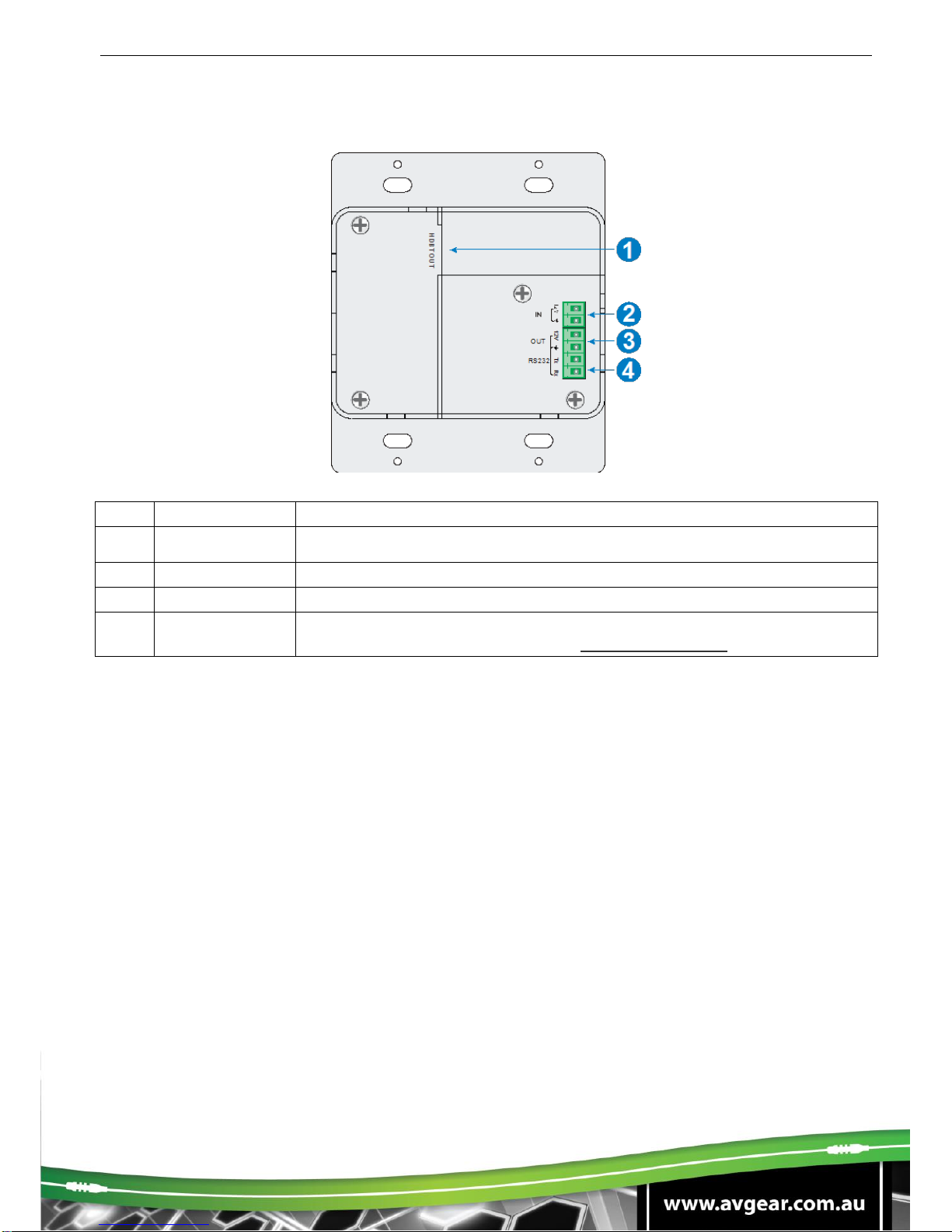
3.2. Rear Panel
No.
Name
Description
①
HDBT OUT
HDBaseT output, connects to the HDBaseT Receiver over a single Cat cable to
deliver AV signals, it supports PoC.
②
IN
12V input, connects with power adapter.
③
OUT
12V output, connects with Control Panel to energize it.
④
RS232
Serial port for control of the AVG-HDWP70HD and a third-party device via
RS232 commands. Please refer to the 5.2. RS232 Control for more details.
Note: Pictures shown in this manual are for reference only.

AVG-HDWP70HD
4. System Connection
4.1. System Applications
Reliable performance for control and transmission makes the AVG-HDWP70HDideal in the IT
computer space, signal monitoring, big screen displays, conference systems, television broadcast,
education, banking and security institutions etc.
4.2. Usage Precautions
1. System should be installed in a clean environment with temperature and humidity maintained to
within equipment specification.
2. All of the power switches, plugs, sockets and power cords should be insulated and safe.
3. All devices should be connected before power is turned on.
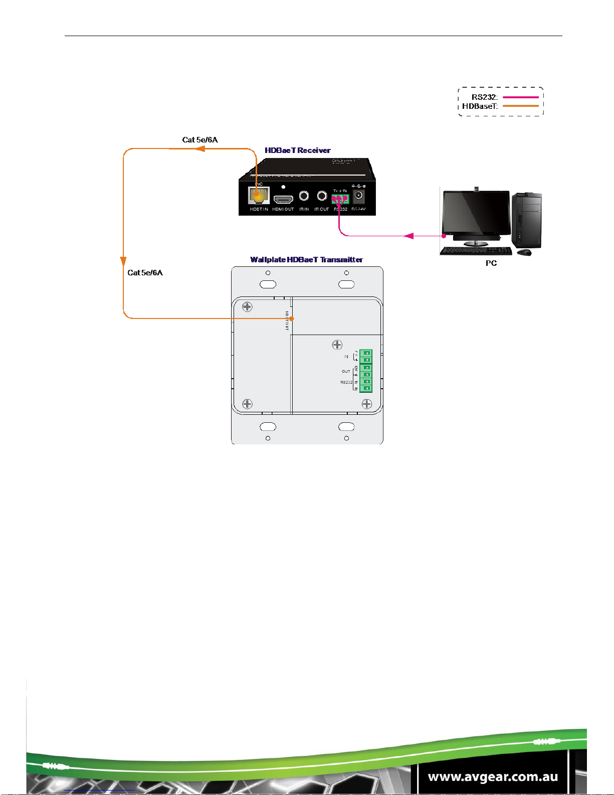
4.3. Connection Diagram
Note: Pictures shown in this manual are for reference only.

AVG-HDWP70HD
4.4. Connection Procedure
1. If installing in a back-box, it is recommended that the transmitter be installed in a 4-5/8”
square box at a minimum. The 4-5/8” square box has sufficient space to terminate the
cables with jacks behind the unit when fully installed.
2. Run one twisted pair cable from the transmitter location to the location where the HDBaseT
Receiver will be located.
3. If using the WP8 Control Panel or a third-party control system, run another twisted pair
cable from the transmitter location to the location that the Control device will be located.
4. All twisted pair cables should be terminated with RJ45 plugs. This allows the permanent link
between the two devices to be tested.
5. If using the WP8 Control Panel or a third-party control system, follow the installation
instructions for the device you are connecting it to.
Note: Category 6A cabling with alien crosstalk prevention technology is recommended to be used
for ensuring the performance of the HDBaseT link.

AVG-HDWP70HD
5. Operations
5.1. Operations of the front panel buttons
Press and hold the SOURCE/AUTO button for approximately 3 seconds. When the button lights
up green the transmitter is in AUTO mode. This mode automatically selects the last video source
connected to the transmitter and outputs it to the display. Press and hold again for approximately 3
seconds, the light will go out, and the device will be in Manual mode which will allow the user to
momentarily press the button to toggle between the two HDMI sources.
5.2. RS232 Control
There are two RS232 control modes switching via sending 50779% or 50780%.
①Control this transmitter and a far-end third-party device (such as a LCD) device by local PC, as
per the connection diagram below:
AVG-HDWP70HD
②Control the transmitter by a remote PC which is connected to the HDBT Receiver.
The RS232 control mode can be selected via RS232 commands.
5.2.1. Installation/removal of the RS232 Control Software
Installation: Copy the control software file to the control PC.
Removal: Delete all the control software files in corresponding file path.
5.2.2. Basic Settings
First, connect the AVG-HDWP70HD with all the input devices and output devices required, then
connect it to a computer which has the installed RS232 control software. Double-click the software
icon to run this software.
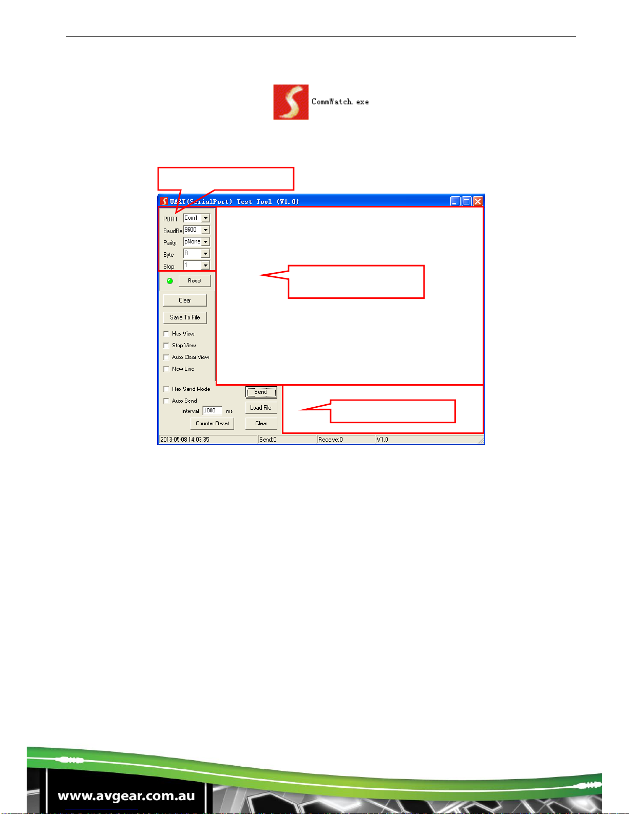
AVG-HDWP70HD
Here we take the software CommWatch.exe as example. The icon is showed as below:
The interface of the control software is showed as below:
Please set the parameters of COM number, baud rate, data bit, stop bit and the parity bit correctly,
and then you can send command in Command Sending Area.
Parameter Configuration area
Monitoring area,
indicates if the
Command Sending area

AVG-HDWP70HD
RS232 Control
Baud rate: 9600 Data bit: 8 Stop bit: 1 Parity bit: none
Control Mode Switching
Command
Description
Feedback Example
50779%
Switch to RS232 mode 1 (Default), control the
transmitter and the far-end third-party device.
RS232 Mode 1: RS232 Control
Scaler & Remote
50780%
Switch to RS232 mode 2, control the transmitter
from remote.
RS232 Mode 2:RS232 & Remote
Control Scaler
Signal Switching
Command
Description
Feedback Example
50770%
Enable auto-switching
Auto Switching
50771%
Disable auto-switching
Manual Switching
50701%
Switch to HDMI input 1
Switch to HDMI 1
50702%
Switch to HDMI input 2
Switch to HDMI 2
HDCP Compliance
Command
Description
Feedback Example
50790%
Set the HDCP status of HDMI output socket to
Active mode.
HDCP Active
50793%
Report HDCP status.
HDCP Off/ HDCP On/
HDCP Active (default)
EDID Configuration
Command
Description
Feedback Example
50772%
EDID pass-through (default)
EDID: bypass mode
50773%
Set EDID data to 1080P PCM 2.0CH
EDID:1080P&PCM 2ch
50774%
Set EDID data to 1080P Dolby 5.1
EDID:1080P&5.1ch
50775%
Set EDID data to 1080P 3D Dolby 5.1
EDID:1080P3d&5.1ch
50776%
Set EDID data to 1080I PCM 2.0 CH
EDID:1080i&PCM 2ch
50777%
Set EDID data to 4Kx2K PCM 2.0 CH
EDID:4K&PCM 2ch
50786%
Switch to customized EDID data.
EDID:user
50799%
Program EDID file, send EDID data within 10s
Waiting for edid within 10 secs!
50778%
Report EDID data.
EDID:1080P&PCM 2ch
EDID:1080P&5.1ch
EDID:1080P3d&5.1ch
EDID:4K&PCM 2ch
EDID:1080i&PCM 2ch
EDID:bypass mode
EDID:User define
System Setting
Command
Description
Feedback Example
50698%
Software upgrading
50699%
Check the software version
Version Vx.x.x
50617%
Restore factory default

AVG-HDWP70HD
6. Specification
Input & Output
Input
(2) HDMI; (1) 12V POWER ;
Input Connector
(2) 19-pin Type A female HDMI;
(1) 2-pin Phoenix plug
Output
(1) HDBaseT; (1) 12V POWER
Output Connector
(1) RJ45; (1) 2-pin Phoenix plug
Transmission Mode
HDBaseT
Control Part
Control Ports
(1) FIRMWARE; (1) RS232
Control Connector
(1) Micro USB; (1) 3-pin Phoenix plug
General
Video Resolution
Up to 4Kx 2K@60Hz 4:2:0
Transmission Distance
1080p ≤ 70M; 4Kx2K ≤ 40M
Bandwidth
10.2Gbps
HDMI Standard
Support HDMI1.4 and HDCP complaint
External Power Supply
Input:100V~240V AC; Output: 12VDC 2A
Max Consumption
9.6W
Operation Temperature
-10 ~ +40℃
Storage Temperature
-15 ~ +55℃
Relative Humidity
10% ~ 90%
Dimension (W*H*D)
104.5mm x 89.0mm x 44.0 mm
Net Weight
238g

AVG-HDWP70HD
7. Panel Drawing
Note: Pictures shown in this manual are for reference only.
LINK
RESET
FIRMWARE
SOURCE/AUTO
HDMI IN 1
POWER
HDMI 1 HDMI 2
HDMI IN 2
12V Tx Rx
OUT
RS232
HDBT OUT
104.5 mm
89.0 mm
66.0 mm
32.0mm
69.0 mm
47.0 mm

AVG-HDWP70HD
8. Troubleshooting & Maintenance
Problems
Causes
Solutions
Color loss or no video
signal output on HDMI
display
The connecting cables
may not be connected
correctly or may be faulty
Check whether the cables are connected
correctly and in working condition.
No HDMI signal output
on the device while
local HDMI input is in
normal working state
Output image noisy
POWER indicator
doesn’t work or respond
to any operation
Loose or failed power
cord connection
Ensure the power cord connection is good
Cannot control the
device by control device
(e.g. a PC) through
RS232 port
Wrong RS232
communication
parameters
Make sure the RS232 communication
parameters are correct.
Static becomes
stronger when
connecting the video
connectors
Poor grounding
Check the grounding and make sure it is
connected well.
Cannot be controlled
through theRS232 port
or front panel buttons
The unit may have had a
previous fault
Send it to authorized dealer for repairing.
Table of contents
Other AVGear Transmitter manuals


