Stahl ISpac 9146 Series User manual

EN
EN
EN
EN
EN
EN
EN
EN
EN
EN
EN
EN
EN
EN
EN
EN
EN
EN
EN
EN
EN
EN
EN
EN
EN
Manual
Additional languages www.r-stahl.com
EN
Frequency Transmitter
Field Circuit Ex i
Series 9146

2
EN
EN
EN
EN
EN
EN
EN
EN
EN
EN
EN
EN
EN
EN
EN
EN
EN
EN
EN
EN
EN
EN
EN
EN
EN
Frequency Transmitter
Field Circuit Ex i
Series 9146
Contents
1 General Information ............................................................................................3
1.1 Manufacturer .......................................................................................................3
1.2 Information about the Manual .............................................................................3
1.3 Further Documents .............................................................................................3
1.4 Conformity with Standards and Regulations .......................................................3
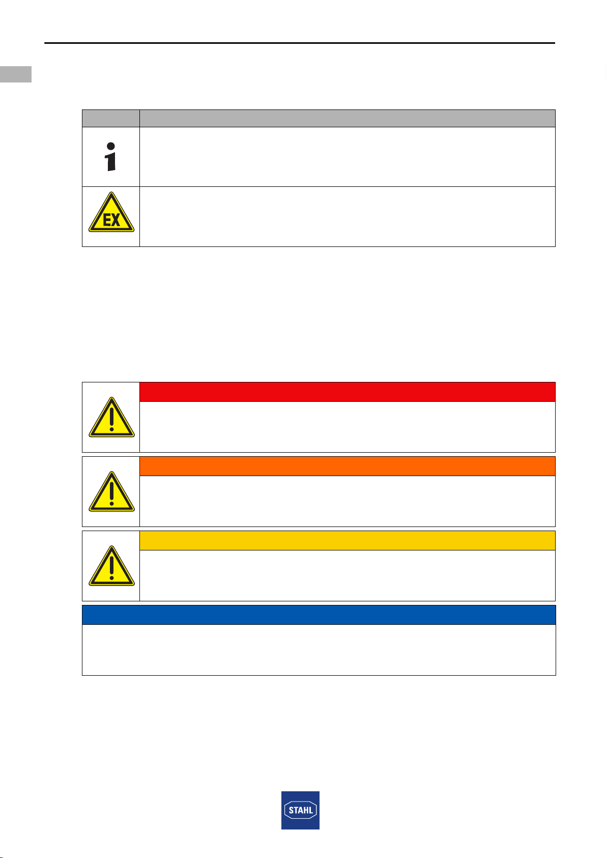
2 Explanation of the Symbols ................................................................................4
2.1 Symbols used in this Manual ..............................................................................4
2.2 Warning Notes ....................................................................................................4
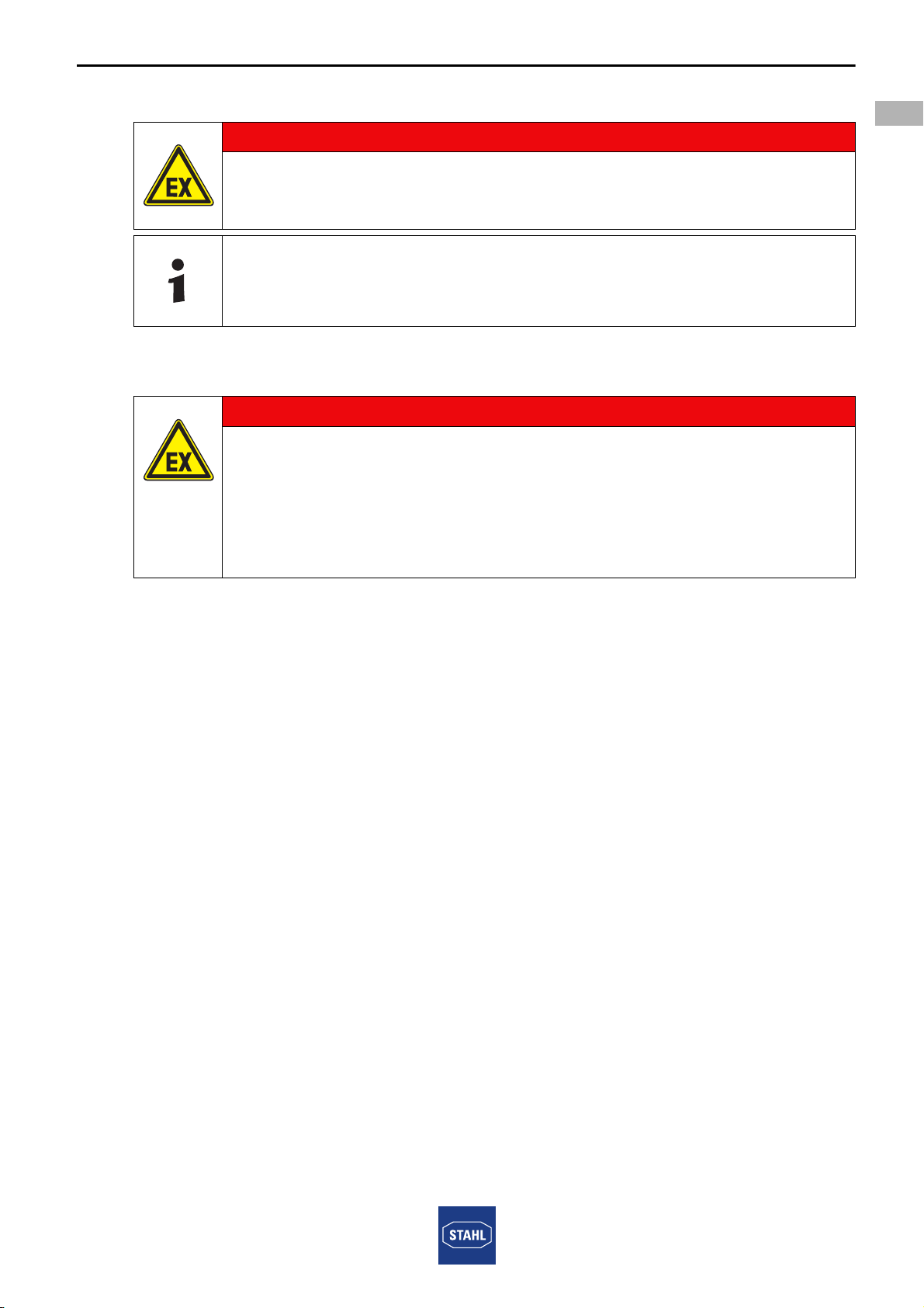
2.3 Symbols on the Device .......................................................................................5
3 Safety Notes .......................................................................................................5
3.1 Storage of the Manual .........................................................................................5
3.2 Personnel Qualification .......................................................................................5
3.3 Safe Use .............................................................................................................6
3.4 Modifications and Alterations ..............................................................................7
4 Function and Device Design ...............................................................................7
4.1 Function ..............................................................................................................7
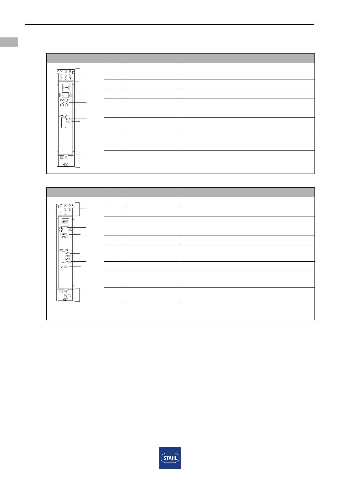
4.2 Device Design .....................................................................................................8
5 Technical Data ....................................................................................................9
6 Engineering .......................................................................................................12
7 Transport and Storage ......................................................................................12
8 Mounting and Installation ..................................................................................13
8.1 Dimensions / Fastening Dimensions .................................................................13
8.2 Mounting / Dismounting, Operating Position .....................................................14
8.3 Installation .........................................................................................................16
9 Parameterization and Commissioning ..............................................................18
9.1 Replacement of the Device ...............................................................................18
9.2 Parameterizations .............................................................................................19
10 Operation ..........................................................................................................22
10.1 Operation ..........................................................................................................22
10.2 Indications .........................................................................................................22
10.3 Troubleshooting ................................................................................................23
11 Maintenance, Overhaul, Repair ........................................................................23
11.1 Maintenance .....................................................................................................23
11.2 Overhaul ...........................................................................................................24
11.3 Repair ...............................................................................................................24
11.4 Returning the Device ........................................................................................24
12 Cleaning ............................................................................................................25
13 Disposal ............................................................................................................25
14 Accessories and Spare Parts ...........................................................................25

914660330020
2017-11-24·HB00·III·en·00
General Information
3
EN
EN
EN
EN
EN
EN
EN
EN
EN
EN
EN
EN
EN
EN
EN
EN
EN
EN
EN
EN
EN
EN
EN
EN
EN
Frequency Transmitter
Field Circuit Ex i
Series 9146
1 General Information
1.1 Manufacturer
R. STAHL Schaltgeräte GmbH
Am Bahnhof 30
74638 Waldenburg
Germany
Phone: +49 7942 943-0
Fax: +49 7942 943-4333
Internet: www.r-stahl.com
E-Mail: [email protected]
1.2 Information about the Manual
ID-No.: 914660330020
Publication Code: 2017-11-24·HB00·III·en·00
Hardware version: A
Software version: 01-01
The original manual is the English edition.
This is legally binding in all legal affairs.
1.3 Further Documents
• Cabinet installation guide
• Data sheet 9146
• Operating instructions 9146
• Manual for the pac-Carrier 9195
For documents in additional languages, see www.r-stahl.com.
1.4 Conformity with Standards and Regulations
See certificates and EC Declaration of Conformity: www.r-stahl.com.
The device has IECEx approval. See IECEx homepage: http://iecex.iec.ch/
Further national certificates can be downloaded via the following link:
https://r-stahl.com/en/global/products/support/downloads/.

Explanation of the Symbols
4914660330020
2017-11-24·HB00·III·en·00
EN
EN
EN
EN
EN
EN
EN
EN
EN
EN
EN
EN
EN
EN
EN
EN
EN
EN
EN
EN
EN
EN
EN
EN
EN
Frequency Transmitter
Field Circuit Ex i
Series 9146
2 Explanation of the Symbols
2.1 Symbols used in this Manual
2.2 Warning Notes
Warnings must be observed under all circumstances, in order to minimize the risk due to
construction and operation. The warning notes have the following structure:
• Signalling word: DANGER, WARNING, CAUTION, NOTICE
• Type and source of danger/damage
• Consequences of danger
• Taking countermeasures to avoid the danger or damage
Symbol Meaning
Tips and recommendations on the use of the device
Danger due to explosive atmosphere
DANGER
Danger to persons
Non-compliance with the instruction results in severe or fatal injuries to
persons.
WARNING
Danger to persons
Non-compliance with the instruction can result in severe or fatal injuries
to persons.
CAUTION
Danger to persons
Non-compliance with the instruction can result in light injuries to
persons.
NOTICE
Avoiding material damage
Non-compliance with the instruction can result in material damage to the device
and / or its environment.

914660330020
2017-11-24·HB00·III·en·00
Safety Notes
5
EN
EN
EN
EN
EN
EN
EN
EN
EN
EN
EN
EN
EN
EN
EN
EN
EN
EN
EN
EN
EN
EN
EN
EN
EN
Frequency Transmitter
Field Circuit Ex i
Series 9146
2.3 Symbols on the Device
3 Safety Notes
3.1 Storage of the Manual
• Read the manual carefully.
• Store the manual at the mounting location of the device.
• Observe applicable documents and operating instructions of the devices to be
connected.
3.2 Personnel Qualification
Qualified specialist personnel are required to perform the tasks described in this manual.
This primarily applies to work in the following areas:
• Project engineering
• Mounting/dismounting the device
• (Electrical) installation
• Commissioning
• Maintenance, repair, cleaning
Specialists who perform these tasks must have a level of knowledge that meets
applicable national standards and regulations.
Additional knowledge is required for tasks in hazardous areas! R. STAHL recommends
having a level of knowledge equal to that described in the following standards:
• IEC/EN 60079-14 (Electrical installations design, selection and construction)
• IEC/EN 60079-17 (Inspection and maintenance of electrical installations)
• IEC/EN 60079-19 (Equipment repair, overhaul and reclamation)
Symbol Meaning
05594E00
CE marking in accordance with the current applicable directive.
02198E00
Electrical circuit certified for hazardous areas according to the marking.
15649E00
Input
15648E00
Output
11048E00
Safety instructions that must always be observed: For devices with this
symbol, the corresponding data and/or the safety-relevant instructions
contained in this manual must be observed!

Safety Notes
6914660330020
2017-11-24·HB00·III·en·00
EN
EN
EN
EN
EN
EN
EN
EN
EN
EN
EN
EN
EN
EN
EN
EN
EN
EN
EN
EN
EN
EN
EN
EN
EN
Frequency Transmitter
Field Circuit Ex i
Series 9146
3.3 Safe Use
Before assembly
• Read and observe the safety notes in this manual.
• Ensure that the contents of this manual are fully understood by the personnel in
charge.
• Use the device in accordance with its intended and approved purpose only.
• Always consult with R. STAHL Schaltgeräte GmbH if using the device under operating
conditions not covered by the technical data.
• Make sure that the device is not damaged.
• We are not liable for damage caused by incorrect or unauthorised use of the device or
by non-compliance with this manual.
For mounting and installation
• Have mounting and installation performed only by qualified and authorised persons
(see "Qualification of the personnel" section).
• The device is only to be installed in zones for which it is suited based on its marking.
• During installation and operation, observe the information (characteristic values and
rated operating conditions) on the rating, data and information plates located on the
device.
• Before installation, make sure that the device is not damaged.
• Install the device in Zone 2 or Zone 22 or outside of hazardous areas.
• For use in Zone 2 or Zone 22, install the device in an enclosure.
• When used in Zones 2, 22, the intrinsically safe devices of Zones 1, 0, 21 and 20 can
be connected to the intrinsically safe signal circuits.
• Only connect the device to equipment which does not carry voltages higher than
253 V AC (50 Hz).
• Devices of group M1 can also be connected to the Ex i electrical circuits.
• Electric circuits with the "Ex i" type of protection can no longer be operated as circuits
with this protection type after being operated with circuits with other types of protection.
Commissioning, maintenance, repair
• Only have commissioning and repairs performed by qualified and authorised persons
(see "Personnel qualification" section).
• Before commissioning, make sure that the device is not damaged.
• Only perform maintenance work described in this manual.

914660330020
2017-11-24·HB00·III·en·00
Function and Device Design
7
EN
EN
EN
EN
EN
EN
EN
EN
EN
EN
EN
EN
EN
EN
EN
EN
EN
EN
EN
EN
EN
EN
EN
EN
EN
Frequency Transmitter
Field Circuit Ex i
Series 9146
3.4 Modifications and Alterations
4 Function and Device Design
4.1 Function
Application range
The frequency transmitter is used for monitoring the rpm of rotating machines or
system sections in hazardous areas. The connected sensor or contact can be installed
in Zones 0, 1 or Div 1, 2.. The device is permitted for use in Zones 2 and 22 as well as
outside of hazardous areas.
Mode of operation
The frequency transmitter converts intrinsically safe binary input signals into analog
signals proportional to the frequency (non-intrinsically safe). Initiators according to
IEC/EN 60947-5-6 (NAMUR) or potential-free contacts / optocoupler outputs with
suitable resistance wiring can be used as signal transducers. The 9146/10-11-12 variant
additionally provides the function of limit value output or pulse forwarding.
DANGER
Explosion hazard due to modifications and alterations to the device!
Non-compliance results in severe or fatal injuries.
• Do not modify or alter the device.
No liability or warranty for damage resulting from modifications and
alterations.
DANGER
Explosion hazard due to improper use!
Non-compliance results in severe or fatal injuries.
• The device may only be used according to the operating conditions
described in this manual.
• Use the device only for the intended purpose specified in this
manual.

Function and Device Design
8914660330020
2017-11-24·HB00·III·en·00
EN
EN
EN
EN
EN
EN
EN
EN
EN
EN
EN
EN
EN
EN
EN
EN
EN
EN
EN
EN
EN
EN
EN
EN
EN
Frequency Transmitter
Field Circuit Ex i
Series 9146
4.2 Device Design
Type 9146/10-11-12, 1-channel
Type 9146/20-11-11, 2-channel
#Device component Description
07420E00
1Black/
green terminals
Connection terminals for the safe area
2 "PWR" LED, green Auxiliary power indication
3 "LF1" LED, red Indication of line fault detection
5 DIP switch "LF1" Activation of line fault detection
6 DIP switch "ADJ1" Manual resetting of the counter function
9 Blue terminals Connection terminals for the hazardous area
(intrinsically safe Ex i)
10 Parameterization
interface
Configuration of the device by means of the
"ISpac Wizard" software Type 9199
11 "A" / "B" LED, yellow Indication for limit contacts
#Device component Description
07421E
1 Black terminals Connection terminals for the safe area
2 "PWR" LED, green Auxiliary power indication
3 "LF1" LED, red Indication of line fault detection for channel 1
4 "LF2" LED, red Indication of line fault detection for channel 2
5 DIP switch "LF1" Activation of line fault detection for channel 1
6 DIP switch "ADJ1" Manual resetting of the counter function for
channel 1
7 DIP switch "LF2" Activation of line fault detection for channel 2
8 DIP switch "ADJ2" Manual resetting of the counter function for
channel 2
9 Blue terminals Connection terminals for the hazardous area
(intrinsically safe Ex i)
10 Parameterization
interface
Configuration of the device by means of the
"ISpac Wizard" software Type 9199
23
5
1
9
10
11
6
9146
23
5
1
9
10
6
4
78
9146

914660330020
2017-11-24·HB00·III·en·00
Technical Data
9
EN
EN
EN
EN
EN
EN
EN
EN
EN
EN
EN
EN
EN
EN
EN
EN
EN
EN
EN
EN
EN
EN
EN
EN
EN
Frequency Transmitter
Field Circuit Ex i
Series 9146
5 Technical Data
Marking
Type designation 9146/.0-11-1.
CE marking C0158
Explosion Protection
Global (IECEx)
Gas, dust and
mining
IECEx BVS 13.0095X
Ex nA nC [ia Ga] IIC T4 Gc
[Ex ia Da] IIIC
[Ex ia Ma] I
Europe (ATEX)
Gas, dust and
mining
BVS 05 ATEX E 171 X
E II 3 (1) G Ex nA nC [ia Ga] IIC T4 Gc
E II (1) D [Ex ia Da] IIIC
E I (M1) [Ex ia Ma] I
Certifications and certificates
Certificates IECEx, ATEX, Canada (cFM), Kazakhstan (TR), Russia (TR), USA (FM),
Belarus (TR)
Ship approval DNV GL, CCS, EU RO MR
Safety data
Max. voltage Uo10.5 V
Max. current Io23.4 mA
Max. power Po61.4 mW
Max. connectable
capacitance Co
IIC 2.41 mF
IIB/IIIC 16.8 mF
IIA 75 mF
I95 mF
Max. connectable
inductance Lo
IIC 63 mH
IIB/IIIC 230 mH
IIA 450 mH
I600 mH
Internal
capacitance Ci
negligible
Internal inductance Linegligible
Safety-related
maximum voltage
253 V

Technical Data
10 914660330020
2017-11-24·HB00·III·en·00
EN
EN
EN
EN
EN
EN
EN
EN
EN
EN
EN
EN
EN
EN
EN
EN
EN
EN
EN
EN
EN
EN
EN
EN
EN
Frequency Transmitter
Field Circuit Ex i
Series 9146
Technical Data
Electrical data
Auxiliary power
Nominal
voltage UN
24 V DC
Voltage range 18 to 31.2 V
Residual ripple
within voltage
range
( 3.6 VSS
Nominal current
at UN
1 channel 55 mA
2 channels 75 mA
Power
consumption at UN
1 channel 1.32 W
2 channels 1.8 W
Polarity reversal
protection
yes
Ex i input
Input signal according to IEC/EN 60947-5-6 (NAMUR)
Current for
ON / OFF
ON 2.1 mA
OFF 1.2 mA
Hysteresis 0.2 mA
Open-circuit
voltage
8.5 V
Short-circuit
current
( 8.5 mA
Input frequency 0.001 to 20000 Hz
Impulse width /
break
25 ms
Resolution < 0.1 % of measurement range
Output
Output signal
(configurable)
0/4 to 20 mA
Functional range 0 to 20.5 mA
Connectable load
resistance
0 to 600 O
Operating mode counter, frequency by period, gate time

914660330020
2017-11-24·HB00·III·en·00
Technical Data
11
EN
EN
EN
EN
EN
EN
EN
EN
EN
EN
EN
EN
EN
EN
EN
EN
EN
EN
EN
EN
EN
EN
EN
EN
EN
Frequency Transmitter
Field Circuit Ex i
Series 9146
For further technical data, see www.r-stahl.com.
Pulse output
Frequency range 0 to 5 kHz
Dividing ratio
Input / Output
1:1 to 1:20000
Switching voltage ( ± 30 V
Switching current ( 50 mA
Parameterisation via Software ISpac Wizard
Activated impulse output allocates contact "B"
(see connection diagram)
Electromagnetic
compatibility
Tested in accordance with the following standards and regulations:
IEC/EN 61326-1 application in industrial environments;
NAMUR NE 21
Ambient conditions
Ambient temperature
Single device -40 to +70 °C
Group assembly -40 to +60 °C
The installation conditions affect the ambient temperature.
Observe the "Cabinet installation guide".
Storage temperature -40 to +80 °C
Relative humidity
(no condensation)
( 95 %
Use at the height of < 2000 m
Mechanical data
Connection
Technical Data
Screw terminals Spring clamp terminals
Single-wire connection
- rigid
- flexible
- flexible with core end sleeves
(without / with plastic sleeve)
0.2 to 2.5 mm2
0.2 to 2.5 mm2
0.25 to 2.5 mm2
0.2 to 2.5 mm2
0.2 to 2.5 mm2
0.25 to 2.5 mm2
two-wire connection
- rigid
- flexible
- flexible with core end sleeves
0.2 to 1 mm2
0.2 to 1.5 mm2
0.25 to 1 mm2
–
–
0.5 to 1 mm2

Engineering
12 914660330020
2017-11-24·HB00·III·en·00
EN
EN
EN
EN
EN
EN
EN
EN
EN
EN
EN
EN
EN
EN
EN
EN
EN
EN
EN
EN
EN
EN
EN
EN
EN
Frequency Transmitter
Field Circuit Ex i
Series 9146
6 Engineering
7 Transport and Storage
• Transport and store the device only in the original packaging.
• Store the device in a dry place (no condensation) and vibration-free.
• Do not drop the device.
NOTICE
Failure of the devices installed in the cabinet caused by too high ambient
temperature!
Non-compliance can result in material damage.
• Install and adjust the cabinet in such a way that it is always operated within
the permissible temperature range.
• Carefully observe the "Cabinet installation guide".
You can find detailed information about project engineering in the
"Cabinet installation guide" (download from www.r-stahl.com,
Product documentation, subitem "Engineering").

914660330020
2017-11-24·HB00·III·en·00
Mounting and Installation
13
EN
EN
EN
EN
EN
EN
EN
EN
EN
EN
EN
EN
EN
EN
EN
EN
EN
EN
EN
EN
EN
EN
EN
EN
EN
Frequency Transmitter
Field Circuit Ex i
Series 9146
8 Mounting and Installation
When installed in a corresponding suitable field enclosure, the device is permitted for use
in hazardous areas in Zone 2 and Zone 22 or in safe areas.
8.1 Dimensions / Fastening Dimensions
DANGER
Explosion hazard due to installation without field enclosure!
Non-compliance results in severe or fatal injuries!
• When used in Zone 2 or Zone 22, the device is to be installed in a
protective enclosure or in a cabinet that offers a suitable degree of
protection in accordance with IEC/EN 60079-0.
• An enclosure with at least an IP54 protection rating is required for
use in Zone 2 and in safe areas.
• An enclosure with at least an IP64 protection rating is required for
use in Zone 22.
DANGER
Explosion hazard due to incorrect installation of the device!
Non-compliance results in severe or fatal injuries.
• Carry out installation strictly according to the instructions and
national safety and accident prevention regulations to maintain the
explosion protection.
• Select and install the electrical device so that explosion protection
is not affected due to external influences, i.e. pressure conditions,
chemical, mechanical, thermal and electric impact such as
vibration, humidity and corrosion (see IEC/EN 60079-14).
• The device must only be installed by trained qualified personnel
who is familiar with the relevant standards.
Dimensional drawings (all dimensions in mm [inches]) – Subject to modifications
09685E00
X
122 4 80[, ]
114,5 4 51[, ]
99 3 90[, ] 17,6 [0,69]
Dimension X
Screw terminals 108 mm [4.25"]
Spring clamp
terminals
128 mm [5.08"]

Mounting and Installation
14 914660330020
2017-11-24·HB00·III·en·00
EN
EN
EN
EN
EN
EN
EN
EN
EN
EN
EN
EN
EN
EN
EN
EN
EN
EN
EN
EN
EN
EN
EN
EN
EN
Frequency Transmitter
Field Circuit Ex i
Series 9146
8.2 Mounting / Dismounting, Operating Position
8.2.1 Mounting / Dismounting pac-Bus
The pac-Bus is an accessory which facilitates wiring of the auxiliary power and reading
out of the collective error message.
Mounting
Dismounting
• Proceed in the reverse order to mounting.
8.2.2 Mounting / Dismounting of the Device on Top Hat Rail and pac-Bus
Mounting on top hat rail
The components for the pac-Bus Type 9194 must be ordered separately.
07392E00
• Connect the required number of pac-Bus elements.
07391E00
• Engage the pac-Bus elements on the top hat rail.
15551E00
• Connect the terminal set at the beginning and at the end.
06886E00
• Position the device on the top hat rail. Position the cut-out
of the enclosure on the outside edge of the top hat rail.
• Engage the device on the top hat rail.
• When swivelling the device onto the top hat rail,
make sure that it is not set at an angle.

914660330020
2017-11-24·HB00·III·en·00
Mounting and Installation
15
EN
EN
EN
EN
EN
EN
EN
EN
EN
EN
EN
EN
EN
EN
EN
EN
EN
EN
EN
EN
EN
EN
EN
EN
EN
Frequency Transmitter
Field Circuit Ex i
Series 9146
Mounting on pac-Bus
Dismounting
8.2.3 Mounting / Dismounting on pac-Carrier
Mounting
Dismounting
15554E00
The pac-Bus is equipped with a polarisation guide and the
device with a matching slot.
• Position the device as shown in the illustration.
Position the cut-out of the enclosure on the outside
edge of the top hat rail.
• Engage the device on the pac-Bus.
06881E00
• Pull out the base bolt somewhat using a screwdriver.
• Swivel out the device.
12613E00
• Remove the black and green terminals.
• For single-channel devices: remove the covering in
terminal slot 2 (between the black and the green
terminal).
15569E00
• Position the device on the pac-Carrier. Place the cut-out
of the enclosure on the outside edge of the pac-Carrier.
• When pivoting the device onto the pac-Carrier,
make sure that it is not set at an angle.
• Swivel in the device up to the red notch lever.
• Close red notch lever by applying diagonal pressure on
the lever with the thumb until the lever engages audibly at
the device.
• Ensure that the red notch lever is engaged.
15574E00
• Swivel out the notch lever using a screwdriver.
• Swivel device out of the slot.

Mounting and Installation
16 914660330020
2017-11-24·HB00·III·en·00
EN
EN
EN
EN
EN
EN
EN
EN
EN
EN
EN
EN
EN
EN
EN
EN
EN
EN
EN
EN
EN
EN
EN
EN
EN
Frequency Transmitter
Field Circuit Ex i
Series 9146
8.2.4 Mounting / Dismounting pluggable Terminals
Mounting
• Plug the terminal into the device until the terminal engages.
Dismounting
8.3 Installation
8.3.1 Electrical Connections
10859E00
• Position the screwdriver behind the terminal.
• Push out the terminal.
Operation under difficult conditions, such as, in particular, on ships, requires
additional measures to be taken for correct installation, depending on the
place of use. Further information and instructions on this can be obtained
from your regional sales contact on request.
DANGER
Explosion hazard caused by too high voltage!
Non-compliance results in severe or fatal injuries.
• Connect the device only to equipment with internal voltage
Um: max. 253 V AC / 50 Hz.
• Connect the device only to intrinsically safe terminals.
DANGER
Explosion hazard due to incorrect safety characteristic values of the
device or connected field devices!
Non-compliance results in severe or fatal injuries.
• Check safety characteristic values of the device and connected
field devices according to the national installation guidelines.

914660330020
2017-11-24·HB00·III·en·00
Mounting and Installation
17
EN
EN
EN
EN
EN
EN
EN
EN
EN
EN
EN
EN
EN
EN
EN
EN
EN
EN
EN
EN
EN
EN
EN
EN
EN
Frequency Transmitter
Field Circuit Ex i
Series 9146
8.3.2 Schematic Diagrams
Type 9146/10-11-12
1 channel, with limit value contacts
Type 9146/20-11-11
2 channels
11019E
11020E
passive
pac-Bus
Division 1
Zone 0/ 1
Division 2
Zone 2
Field device ISpac Isolator Control system
Hazardous area Safe area
Division 1
Zone 0/ 1
Division 2
Zone 2
pac-Bus
passive
Field device ISpac Isolator Control system
Hazardous area Safe area
passive

Parameterization and Commissioning
18 914660330020
2017-11-24·HB00·III·en·00
EN
EN
EN
EN
EN
EN
EN
EN
EN
EN
EN
EN
EN
EN
EN
EN
EN
EN
EN
EN
EN
EN
EN
EN
EN
Frequency Transmitter
Field Circuit Ex i
Series 9146
8.3.3 Connection of Contacts
Circuitry for line fault detection if the contacts at the input are de-energized:
8.3.4 Connection of Supply
9 Parameterization and Commissioning
Before commissioning, ensure the following:
• Installation of the device according to regulations.
• Correct connection of the cables.
• No damage at the device and connection cables.
• Tight seat of the screws at the terminals.
Correct tightening torque: 0.5 to 0.6 Nm.
9.1 Replacement of the Device
• If replacing by a device with identical design, readjust the DIP switch, if necessary.
Schematic
15529E
Short-circuit detection: 1 k Ω in series
Open-circuit detection: 10 k Ω parallel
Carry out circuitry for line fault detection in the immediate proximity of the
contacts.
Type of supply Connection
Direct supply of the device via 24 V connection Green terminals "7+" and "9-"
Supply via pac-Bus pac-Bus terminals "1+" and "2-"
DANGER
Explosion hazard due to incorrect installation!
Non-compliance results in severe or fatal injuries.
• Check the device for proper installation before commissioning.
• Comply with national regulations.
1 k
10 k

914660330020
2017-11-24·HB00·III·en·00
Parameterization and Commissioning
19
EN
EN
EN
EN
EN
EN
EN
EN
EN
EN
EN
EN
EN
EN
EN
EN
EN
EN
EN
EN
EN
EN
EN
EN
EN
Frequency Transmitter
Field Circuit Ex i
Series 9146
9.2 Parameterizations
9.2.1 DIP Switches "LF" and "ADJ"
The front panel of the frequency transmitter contains a 4-pole DIP switch.
*) Default setting upon delivery, **) see following chapter "Input"
The DIP switches "LF1" and "LF2" are used for activating the line fault detection
(see above table) and for resetting the anti-pumping device
(see chapter "Anti-pumping device"), respectively.
The DIP switches "ADJ1" and "ADJ2" allow the minimum and maximum counts of the
pulse counter for channel 1 and channel 2, respectively, to be reset.
Line faults and auxiliary power failure are signalled via LED, error message
contact at the module and collective error message via pac-Bus
(see chapter "Schematic circuit diagrams of up to 2-channel designs").
Line fault detection
DIP switch "LF"
Resetting the counter function of
DIP switch "ADJ" **)
Deactivated *) Activated OFF-ON-OFF or ON-OFF-ON
Channel 1
Channel 2
15552E00 15553E00 06536E
Changing the DIP switch settings is also permitted during operation in
Zone 2 and with connected intrinsically safe input signals.
The characteristics of the output signal are set by means of the
"ISpac Wizard" software. It also allows the line fault detection to be
completely deactivated. This setting determines the characteristics of the
device, while the DIP switch is completely ineffective in this case.
LF1
ADJ1
LF2
ADJ2
ONOFF
1
2
LF1
ADJ1
LF2
ADJ2
ONOFF
1
2
OFF ON
LF1
ADJ1
1
LF2
ADJ2
2

Parameterization and Commissioning
20 914660330020
2017-11-24·HB00·III·en·00
EN
EN
EN
EN
EN
EN
EN
EN
EN
EN
EN
EN
EN
EN
EN
EN
EN
EN
EN
EN
EN
EN
EN
EN
EN
Frequency Transmitter
Field Circuit Ex i
Series 9146
9.2.2 Input (via "ISpac Wizard" Software)
The frequency transmitter offers different operating modes, which can be set depending
on the application. The default setting is the operating mode "Frequency via period
measurement".
9.2.3 Signal Processing (via "ISpac Wizard" Software)
The selection allows the frequency range to be restricted for further processing inside
the module. The minimum value of the analog output corresponds to the set minimum
frequency and the same is true of the maximum values.
This allows the user to define the frequency range relevant for him and set it in relation
to the range of the output signal (0 to 20 mA or 4 to 20 mA).
9.2.4 Output (via "ISpac Wizard" Software)
Here the characteristics of the analog and pulse outputs can be configured.
Analog output:
Apart from the selection whether the analog signal should adopt values between
0 to 20 mA or 4 to 20 mA, the characteristics of the output in case of error can be defined.
The selections include "Output error value" (freely selectable), "Keep last value" or
"Fault detection off".
Pulse output:
The pulse output can be activated and deactivated. In addition, a splitter ratio of
between 1 and 20,000 can be entered.
Selection Description
Counter (0 to 65535) Incoming pulses are counted. The analog output signal (0/4 to 20 mA)
is increased linearly until reaching the counter value. The maximum counter
value can be set.
Counter overflow If the overflow is activated, the counter will start counting again when the
maximum counter value is exceeded, and the output signal (sawtooth)
will follow.
When the overflow is off, the counter and the analog signal will stop upon
reaching the maximum value.
They can be reset via the front-panel DIP switches "ADJ1 " and
"ADJ2 "(OFF-ON-OFF and ON-OFF-ON, respectively)
Frequency via period
measurement
For measurements in the range from 1 mHz to 1 kHz.
Frequency via events
(50, 200 or 1000 ms)
For measurements in the range from 1 to 20 kHz.
Table of contents
Other Stahl Transmitter manuals

Stahl
Stahl 9162 Series User manual

Stahl
Stahl 9162 Series User manual

Stahl
Stahl 9182 Series User manual

Stahl
Stahl 9146 Series User manual

Stahl
Stahl ispac 9160 User manual

Stahl
Stahl ISpac 9182 Series User manual

Stahl
Stahl ISpac 9162 User manual

Stahl
Stahl 9146 Series User manual

Stahl
Stahl ISpac 9182 Series User manual