AVGear AVG-HDWP70TX-B User manual

AVG-HDWP70TX-B
The
AVG
-
HDWP70TX
-
B
is a Decora style
transmitter that installs in a double-gang wall
box to provide a convenient interface for
HDMI/VGA input sources.
Features
Selectable HDMI/VGA with audio
input
Supports VGA output resolution up to
1920 x1200
High bandwidth: 10.2Gbps
In-built scaler function, supports
scaling of HDMI/VGA signals to match
the native resolution of the display
Transmits HDMI signals up to 4K
Compliant with HDMI 1.4, supports
1080p 3D
HDCP compliant, equipped with
HDCP auto-tracking function
Provides auto-switching capability
Supports multiple control methods
including front panel buttons and
RS232, supports bi-directional RS232
pass-through control.
Supports firmware upgrade via USB.
DC 12V power output
Powered by local power pack or PoC
connection up to 60m
Aluminum design for efficient cooling

PLEASE READ THIS PRODUCT MANUAL CAREFULLY
BEFORE USING THIS PRODUCT.
This manual is only for operation instruction only, and
not to be used in a maintenance capacity. The functions
described in this version are current as at September
2015. Any changes of functions and operational
parameters will be updated in future manual versions.
Please refer to your dealer for the latest product details.
Version 1.2 1/12/15

AVG-HDWP70TX-B
SAFETY OPERATION GUIDE
In order to guarantee the reliable operation of the equipment, please abide by the
following procedures in installation, use and practice. Please save this manual for further
reference.
1. Unpack the equipment carefully and save the original box and packing material for
possible future shipment
2. Follow basic safety precautions to reduce the risk of fire, electrical shock and in ury to
persons.
3. Do not dismantle the housing or modify the module. It may result in electrical shock
or burns.
4. Using supplies or parts not meeting the products’ specifications may cause damage,
deterioration or malfunction.
5. Refer all servicing to qualified service personnel.
6. To prevent fire or shock hazard, do not expose the unit to rain, moisture or install this
product near water.
7. Do not put any heavy items on the extension cable in case of extrusion.
8. Do not remove the housing of the device as opening or removing housing may
expose you to dangerous voltage or other hazards.
9. Install the device in a place with adequate ventilation to avoid damage caused by
overheating.
10. Keep the module away from liquids.
11. Spillage into the housing may result in fire, electrical shock, or equipment damage. If
an ob ect or liquid falls or spills on to the housing, unplug the module immediately.
12. Do not use liquid or aerosol cleaners to clean this unit. Always unplug the power to
the device before cleaning.
13. Unplug the power cord when left unused for a long period of time.
14. Disposal Information: do not burn or mix with general household waste, please treat
as normal electrical wastes.

TABLE OF CONTENTS
Introduction..............................................................................................................1
Introduction to the AVG-HDWP70TX-B........................................................1.1
Features.......................................................................................................1.2
Package List................ ……………………………………………………………………2
Product Appearance................................................................................................3
Front Panel...................................................................................................3.1
Side Panel....................................................................................................3.2
Rear Panel...................................................................................................3.3
System Connection .................................................................................................4
System Application.......................................................................................4.1
Usage Precautions.......................................................................................4.2
Connection Diagram.....................................................................................4.3
Connection Procedure..................................................................................4.4
12V DC Output.............................................................................................4.5
PoCSolution.................................................................................................4.6
Operations................................................................................................................5
Operations of front panel buttons.................................................................5.1
RS232 Control..............................................................................................5.2
Installation/removal of RS232 Control Software........................................5.2.1
Basic Settings ...........................................................................................5.2.2
RS232 Communication Commands..........................................................5.2.3
Specification.............................................................................................................6
Panel Drawing ..........................................................................................................7
Troubleshooting & Maintenance ............................................................................8

AVG-HDWP70TX-B
1. Introduction
1.1.Introduction to the AVG-HDWP70TX-B
The AVG-HDWP70TX-B is a Decora style transmitter that installs in a double-gang wall box to
provide a convenient interface for HDMI / VGA input sources. It has 1 HDMI IN, 1 VGA IN, Audio
IN and 1 HDBaseT OUT with PoC. It supports VGA with a full HD scaler, and HDMI 1.4 with 4k&
3D. Input signals support auto-switching and manual-switching. The HDBaseT output supports
60m UHD video transmission with PoC, it enables bi-directional RS232 communication between
the Scaler Wall Plate HDBaseT Transmitter-B and a remote device.
With its PoC solution,AVG-HDWP70TX-B can be powered by a far-end PoC receiver.
1.2.Features
Selectable HDMI/ VGA with audio input
Supports VGA output resolution up to 1920x1200
High bandwidth: 10.2Gbps
In-built scaler function, supportsscalingHDMI/ VGA signals to match the native resolution of
the display
Transmits HDMI signals up to 4K
Compliant with HDMI 1.4, supports 1080p 3D
HDCP compliant, equipped with HDCP auto-tracking function
Provides auto-switching capability
Supports multiple control methods including front panel buttons, and RS232, supports bi-
directional RS232 pass-through control.
Supports firmware upgrading via USB.
DC 12V power output
Powered by local power pack or PoC connection up to 60m
Aluminum design for efficient cooling

2. Package List
1 x AVG-HDWP70TX-B
4 x Screws (for AVG-HDWP70TX-B)
3 x Pluggable Terminal Blocks (1 2-pin block, 1 3-pin block, and 1 4-pin block)
1 x Face Plate (Selectable)
4 x Screws (for the face plate)
1 x User Manual
Note: Please confirm if the product and the accessories are all included, if not, please contact your
dealer.
AVG-HDWP70TX-B
3. Product Appearance
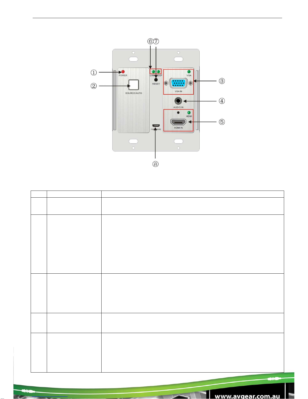
3.1. Front Panel
No.
Name
Description
①
Power indicator Illuminates red when power is on
②SOURCE/ AUTO
Used as video source selection button (with backlight off):
Press to select one source, press again to select next source,
switching circularly between HDMI and VGA. The indicator of the
selected input source will illuminate green.
Used as switching mode selection button (with backlight on):
Press and hold for 3 seconds or more to enter in Auto-switching
mode, the indicator illuminates green when in auto-switching mode.
Press and hold for 3 seconds or more again to enter in Manual-
switching mode.
③VGA IN
Connect with VGA source device.
The indicator:
illuminates yellow when there is VGA signal input
illuminates green when the signal source is chosen as input
source
turns off when there is no VGA input signal
④
AUDIO IN Connect with the audio output socket of VGA source device, delivers
synchronous audio with the VGA signal source when choosing VGA
as source signal.
⑤HDMI IN
Connect with HDMI source device.
The indicator:
illuminates yellow when there is HDMI signal input
illuminates green when the signal source is chosen as input
source
turns off when there is no HDMI input signal

⑥LINK &HDCP
LINK: Twisted Pair Link status indicator, illuminates green when
successfully connected.
HDCP: HDCP compliance indicator, illuminates green when the
source signals contains HDCP; blinks when there is no HDCP. Turns
off when there is no source signal.
⑦
RESET Press the button to reboot the HDBaseT Wallplate Transmitter
⑧
FIRMWARE
USB port, used for firmware update
Plug a flash disk or other storage device with update file
(MERGE.bin), and send the command 50698% to update the
firmware.
Note: Pictures shown in this manual are for reference only.

AVG-HDWP70TX-B
3.2.Side Panel
No. Name
Description
①HDBaseT
OUT RJ45 port, connect with receiver via a CAT5e/6 cable to deliver Audio/
Video signals, supports PoC
Note: Pictures shown in this manual are for reference only.
Note: AVG-HDWP70TX-B supports unidirectional PoC, i.e. it can be powered from the far-end
receiver but it can’t power the far-end receiver.
3.3. Rear Panel
No.
Name Description
①
Power In
Power in port, 2-pin pluggable terminal block, connect with DC 12V power
adapter
②Power Out
12V DC power output for powering 3
rd
party devices
③RS232
Serial port, connects with a far-end receiver, supports bi-directional
RS232 control (sends control signal from local or receives control signal
sent from far-end devices).
Note: Pictures shown in this manual are for reference only.
4. System Connection
4.1. System Applications
Reliable performance for control and transmission makes the AVG-HDWP70TX-Bideal in the IT
computer space, signal monitoring, big screen displays, conference systems, television broadcast,
education, banking and security institutions etc.
4.2.Usage Precautions
1. System should be installed in a clean environment with temperature and humidity maintained to
within equipment specification.
2. All of the power switches, plugs, sockets and power cords should be insulated and safe.
3. All devices should be connected before power is turned on.
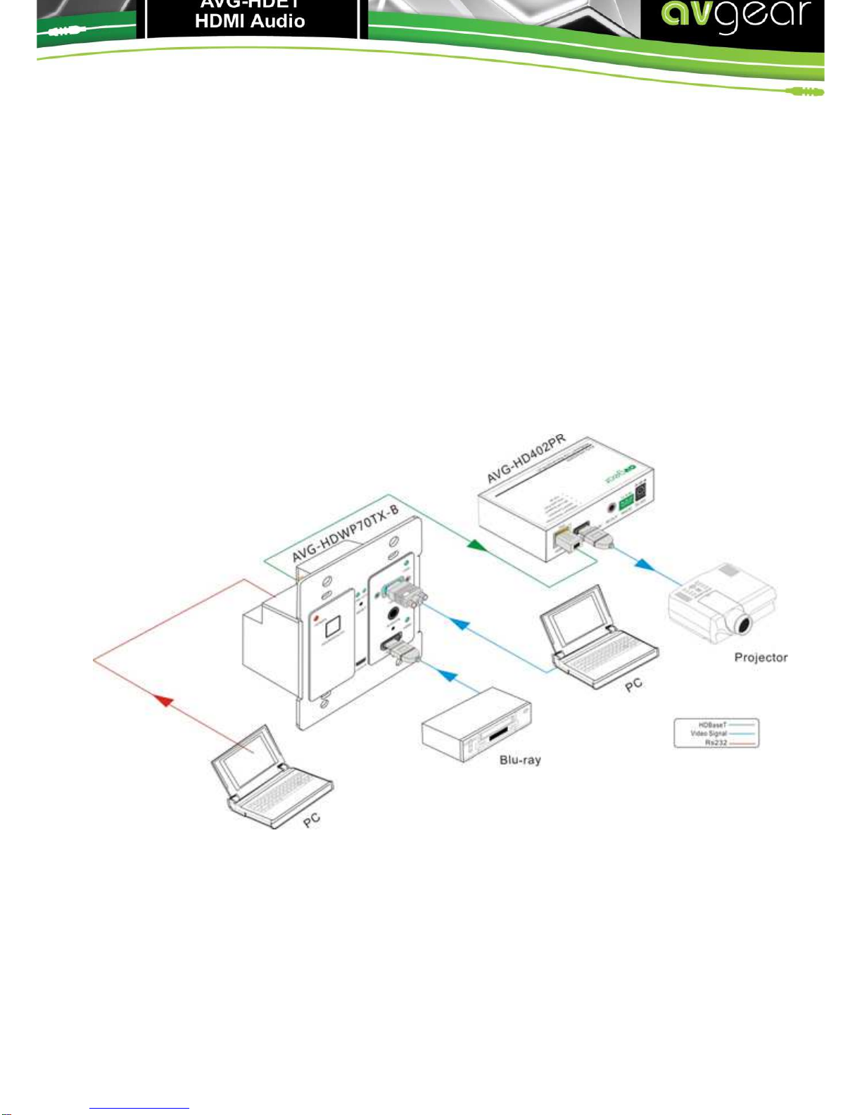
4.3.Connection Diagram
Note: Pictures shown in this manual are for reference only.

AVG-HDWP70TX-B
4.4. Connection Procedure
Step 1. Connect HDMI source device (e.g. Blu-ray DVD) to HDMI input ports ofAVG-
HDWP70TX-B with HDMI cable. Connect a VGA source device (e.g. PC) to the VGA
input port of AVG-HDWP70TX-B with VGA cable.
Step 2. Connect an AVG-HD402PR to the HDBaseT port on the rear panel with twisted pair.
Step 3. Connect a HDMI display to the HDMI OUT port of AVG-HD402PR.
Step 4. Connect a control terminal to the RS232 port on the rear panel of the AVG-
HD402PR.
Step 5. Connect control device (e.g. PC) to the RS232 port of AVG-HDWP70TX-B or AVG-
HD402PR (bi-directional RS232 control, either is available).
Step 6.Connect DC 24V power adaptor to the power port ofAVG-HD402PR, AVG-
HDWP70TX-B is able to get power from AVG-HD402PR with PoC solution.
Note: AVG-HDWP70TX-B supports unidirectional PoC, i.e, AVG-HDWP70TX-B can get power
from far-end PoC devices with the PoC function. However, it cannot power far-end PoC devices
when the power supply is connected.
4.5. 12V DC Power
AVG-HDWP70TX-B has a12V power output port on the rear panel. Connect the12V power
outputportof AVG-HDWP70TX-B tothepower port ofa 3
rd
Party Device for convenient localized
powering.
Note: Pictures shown in this manual are for reference only.
4.6. POC Solution
AVG-HDWP70TX-B has a HDBaseT OUTPUT port on the rear panel, which can extend HDMI/
VGA signals up to 60m. The Scaler also supports PoC, which allows several units to share the
same power supply and eliminates the need for extra power supply’s at the remote nodes.
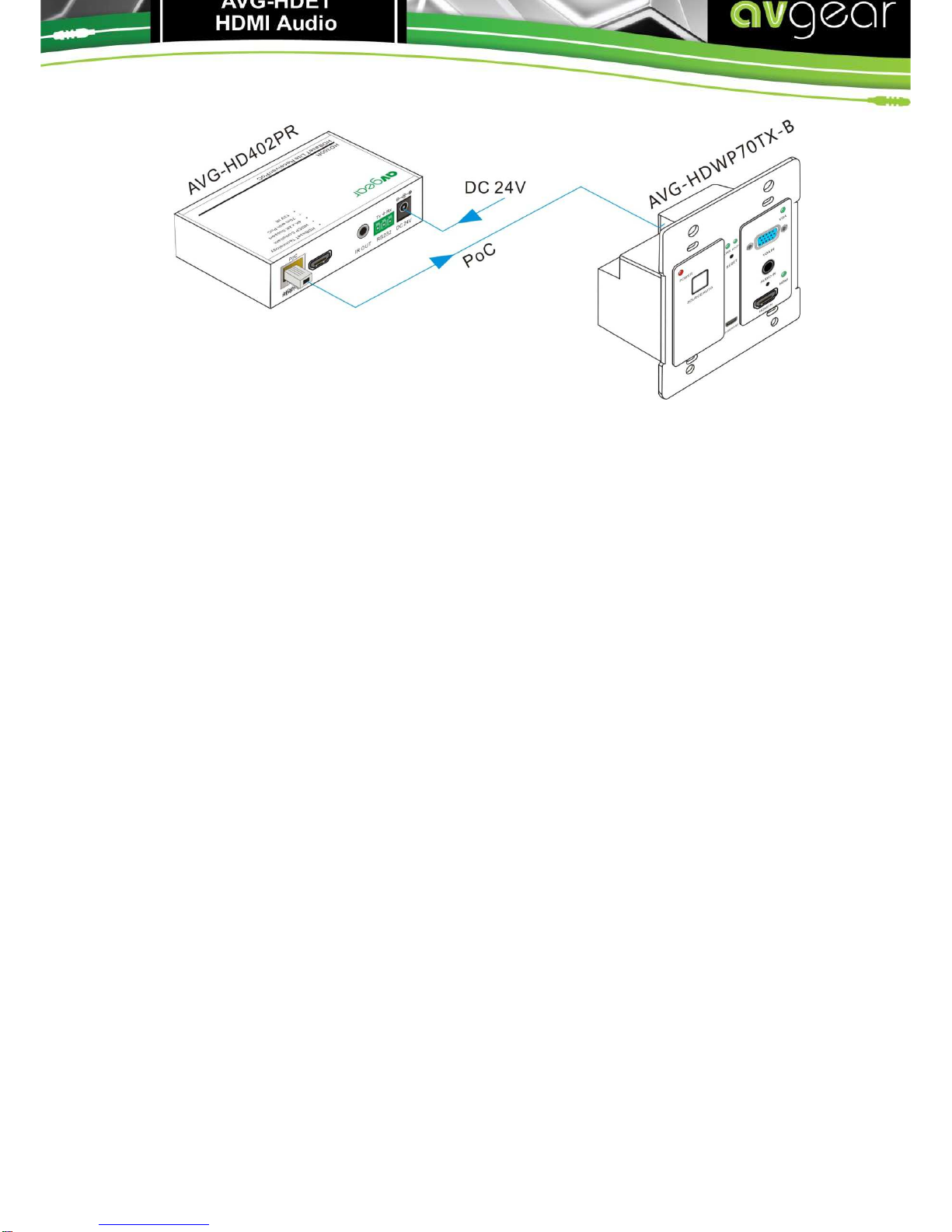
Connect a DC 24V power adapter to the power port of AVG-HD402PR, AVG-HDWP70TX-B can
be powered with the PoC solution, see the picture below:
Note: Pictures shown in this manual are for reference only.

AVG-HDWP70TX-B
5. Operations
5.1.Operations of the front panel buttons
AVG-HDWP70TX-B has a channel switching button on the front panel, through which users can
switch input source signals.
It supports both manual switching and auto switching. (Default: Auto switching) Press and hold the
switching button for 3 seconds or send command “50770% “ and “50771%” to switch between the
two modes.
Switching modes:
Auto switching mode
In this mode, the indicator will illuminates green, and AVG-HDWP70TX-Bwill recognize the last
connected source device as input source automatically. Disconnect the present source device,
it will select the other source signal (if there is input signal on the other source).
Manual switching mode
In this mode, the indicator will remain off. Press the switching button to select input source, it
will alternate between HDMI and VGA. Or switch it by sending RS232 commands.
The indicator of the selected input source will illuminate green.
5.2. RS232 Control
As RS232 can be transmitted bi-directionally between AVG-HDWP70TX-B and AVG-HD402PR, it
is able to control a third party RS232 device locally or control the AVG-HDWP70TX-B from a
remote location. When controlling a third party RS232 device, the baud rate of this device can be
set to 2400, 4800, 9600, 19200, 38400, 57600 or 115200.
5.2.1. Installation/removal of the RS232 Control Software
Installation Copy the control software file to the computer connected with the AVG-
HDWP70TX-B.
Removal Delete all the control software files in corresponding file path.
5.2.2. Basic Settings
First, connect theAVG-HDWP70TX-B with all input devices and output devices needed, then
connect it with a computer which has the installed RS232 control software. Double-click the
software icon to run this software.
Here we take the software CommWatch.exeas an example. The icon is shown as below:
The interface of the control software is showed as below:
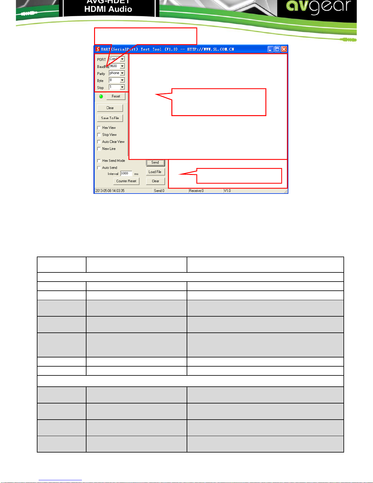
Please set the parameters of COM number, baud rate, data bit, stop bit and the parity bit correctly,
then you are able to send commands in Command Sending Area.
5.2.3. RS232 Communication Commands
Communication protocol: RS232 Communication Protocol
Baud rate: 9600 Data bit: 8 Stop bit: 1 Parity bit: none
Command Function Feedback Example
Switch Commands
50701% Switch to HDMI input Switch to HDMI
50704% Switch to VGA input Switch to VGA
50705% Change the horizontal polarity
to the opposite Hpolarity:0/1
50706% Change the vertical polarity to
the opposite Vpolarity:0/1
50707% Check the present resolution
and polarity
1920x1080
Hpolarity:1
Vpolarity:0
50770% Enable auto-switching Auto Switching
50771% Disable auto-switching Manual Switching
Resolution Commands
50619% Change the resolution to
1360X768 HD Resolution: 1360x768
50626% Change the resolution to
1024X768 XGA Resolution: 1024x768
50627% Change the resolution to
1280X720 720P Resolution: 1280x720
50628% Change the resolution to
1280X800 WXGA Resolution: 1280x800
Parameter Configuration area
Monitoring area, indicates if
the command sent works.
Command Sending area

AVG-HDWP70TX-B
50629% Change the resolution to
1920X1080 1080P Resolution: 1920x1080
50620% Change the resolution
to1920X1200 WUXGA Resolution: 1920x1200
50621% Change the resolution
to1600X1200 UXGA Resolution: 1600x1200
Setup Commands
502xx% Set the brightness to xx. XX
ranges from 00 to 99 Brightness: xx
503xx% Set the contrast to xx. XX
ranges from 00 to 99 Contrast: xx
504xx% Set the saturation to xx. XX
ranges from 00 to 99 Saturation: xx
505xx% Set the sharpness to xx. XX
ranges from 00 to 99 Sharpness: xx
50606% Auto-adjust the input
parameter VGA Input Auto
50607% Adjust the color temperature Color Temperature: xx (xx can be medium,
warm, user, or cool)
50608% Set the aspect ratio Aspect Ratio: xx (xx can be 16:9, 4:3, or auto.)
50614% Set the picture mode Picture Mode: xx (xx can be dynamic, standard,
mild, or user.)
50699% Check the system version Version Vx.x.x
50779% Switch to RS232 mode 1,
enable scaler to control far-
end devices RS232 Mode 1: RS232 Control Scaler & Remote
50780% Switch to RS232 mode 2,
enable far-end devices to
control scaler RS232 Mode 2:RS232 & Remote Control Scaler
50790% Set the HDCP status of HDMI
output socket to Active HDCP Active
50791% Set the HDCP status of HDMI
output socket to On HDCP On
50792% Set the HDCP status of HDMI
output socket to Off HDCP Off
50698% Software update
50617% Reset to factory default
Query Commands
50632% Check the output resolution Resolution: xx
50633% Check the picture mode Picture Mode: xx
50793% Check HDCP status HDCP Off
HDCP On
HDCP Active
50635% Check the image aspect ratio Aspect Ratio: xx
50636% Check the brightness Brightness: xx
50637% Check the contrast Contrast: xx
50638% Check the saturation Saturation: xx
50639% Check sharpness Sharpness: xx
50640% Check the color temperature Color Temperature: xx
Adjustment Commands
50678% Enable screen output adjusting
Enter Output Position Adjust
50679% Disable screen output
adjusting Exit Output Position Adjust
50670% Move the image to left Output Position Adjust X xx
50671% Move the image to right Output Position Adjust X xx
50672% Move the image up Output Position Adjust Y xx
50673% Move the image down Output Position Adjust Y xx
50674% Stretch left from left side
(increase image width) Output Width Adjust xx
50675% Pull right from left side
(decrease image width) Output Width Adjust xx
50676% Stretch upwards from bottom
side (decrease image height) Output Height Adjust xx
50677%
Stretch downwards from
bottom side (increase image
height) Output Height Adjust xx
EDID Commands
50772% EDID pass-through EDID:bypass mode
50773% Set EDID data to 1080P PCM
2.0ch EDID:1080P&PCM 2ch
50774% Set EDID data to
1080P
Dolby 5.1 EDID:1080P&5.1ch
50775% Set EDID data to
1080P3DDolby 5.1 EDID:1080P3d&5.1ch
50776% Set EDID data to 1080i PCM
2.0ch EDID:1080i&PCM 2ch
50777% Set EDID data to 4K*2K PCM
2.0ch EDID:4K&PCM 2ch
50778% Check EDID data
EDID:1080P&PCM 2ch
EDID:1080P&5.1ch
EDID:1080P3d&5.1ch
EDID:4K&PCM 2ch
50799% Program EDID file, send EDID
data within 10s Waiting for edid within 10 secs!
Note:
1. Commands with grey background are for VGA sources only.
2. EDID commands are for HDMI sources only.

AVG-HDWP70TX-B
6. Specification
Video
Input 1 HDMI,1 VGA Output 1 HDBaseT
Input Connector 1 19-pin Type A HDMI
female;
1 15-pin VGA
Output
Connector 1 RJ45
Transmission
Mode HDBaseT
Audio
Input 1 synchronous VGA audio
Input Connector 1 3.5mm stereo jack
Frequency
Response 20Hz~20KHz
Impedance >10ΩSNR >85db@20Hz~20KHz
Control
Control Ports 13-pin RS232 socket on rear panel (shares the ground pole with 12V OUT)
General
Resolution VGA: 800 x600, 1024 x 768, 1280 x 800,1280 x 1024, 1440 x 900,1600 x 1200,
1920 x 1080, 1920 x 1200;
HDMI: 4Kx2K, 1080p 3D, 1080P(HD)/1080i/720P/576P/576i/480P/480i
Transmission
Distance 1080P≤60M (PoC)
4Kx2K≤40M (PoC)
Bandwidth 10.2Gbps
HDMI Standard Support HDMI1.4 and HDCP
Chassis
Dimension Decora style two gang Power Supply DC 12V 2A; 9.6W
Temperature -10 ~ +40℃Reference
Humidity 10% ~ 90%
Dimension
(W*H*D) 104.5 x 89 x 44 mm Weight 0.29Kg
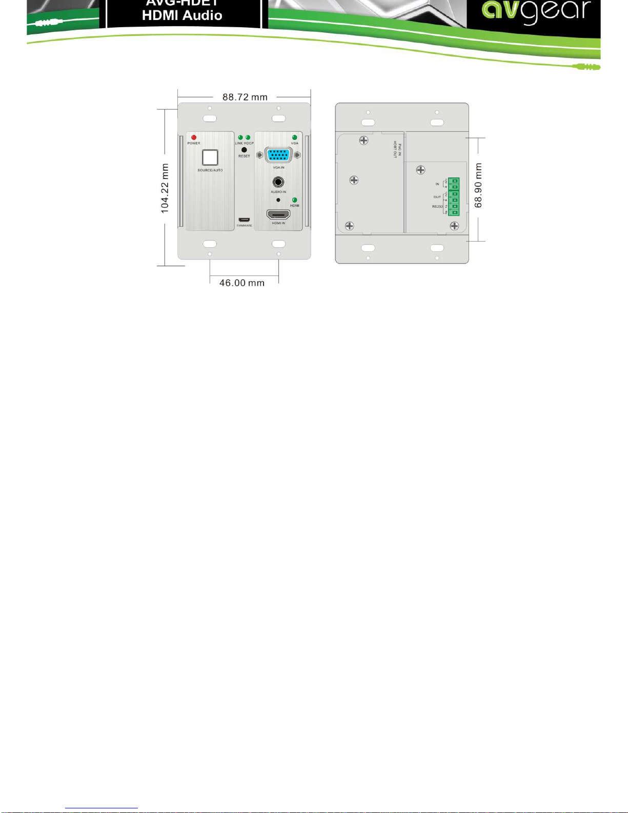
7. Panel Drawing
Note: Pictures shown in this manual are for reference only.

AVG-HDWP70TX-B
8. Troubleshooting & Maintenance
Problems
Causes
Solutions
Color loss or no video
signal output on HDMI
display The connecting cables
may not be connected
correctly or may be faulty
Check whether the cables are connected
correctly and in good working condition.
No HDMI signal output
on the device while
local HDMI input is in
normal working state
Output image noisy
POWER
indicator
doesn’t work or respond
to any operation Loose or failed power
cord connection Ensure the power cord connection is good
Cannot control the
device by control device
(e.g. a PC) through
RS232 port
Wrong
RS232communication
parameters
Make sure the RS232communication
parameters are correct.
Static becomes
stronger when
connecting the video
connectors
Poor grounding Check the grounding and make sure it is
connected well.
Cannot be controlled
through theRS232 port
or front panel buttons
The unit may have had a
previous fault Send it to authorized dealer for repairing.
Other manuals for AVG-HDWP70TX-B
1
Table of contents
Other AVGear Transmitter manuals


Popular Transmitter manuals by other brands


Bellman & Symfon
Bellman & Symfon BE1490 quick start guide

Absolute Process Instruments
Absolute Process Instruments AP11400 G quick start guide

SOMFY
SOMFY inteo TELIS SOLIRIS RTS installation guide

DMP Electronics
DMP Electronics 1106 installation guide

GÜDE
GÜDE Expert Opto Bridge 0403 manual

Lamtec
Lamtec LT2 user manual