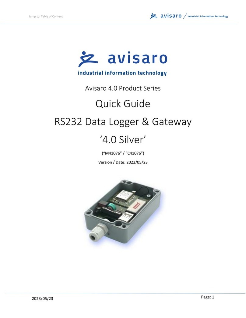
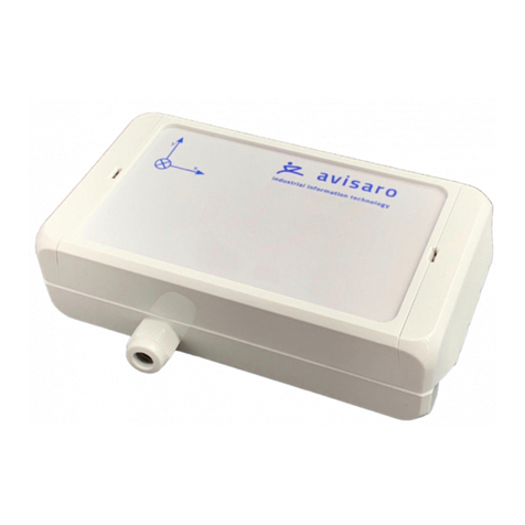
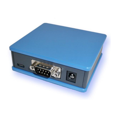
Avisaro 4.0 Series User manual

Jump to: Table of Content
2021/05/12
Page : 2
1TABLE OF CONTENT
2 This document ......................................................................................................................................3
2.1 Location.........................................................................................................................................3
2.2 Other documents..........................................................................................................................3
2.3 Language Versions ........................................................................................................................3
3 Enclosure and User Controls.................................................................................................................4
3.1 Start and stop operation...............................................................................................................4
3.2 LED Blink-Codes.............................................................................................................................4
3.3 Real-Time Clock.............................................................................................................................4
3.4 Enclosure “4.0 Sky” with D-Sub connector...................................................................................5
4 USB Storage Stick..................................................................................................................................6
4.1 Format and Size.............................................................................................................................6
4.2 Choosing the right type.................................................................................................................6
4.3 Choosing the right size..................................................................................................................6
5 Interface description and Pin Layout....................................................................................................7
5.1 RS232 Interface.............................................................................................................................7
5.1.1 Default RS232 settings ..........................................................................................................7
5.1.2 Signal levels...........................................................................................................................7
5.1.3 D-Sub Connector...................................................................................................................7
6 Configuration: ‘PC Companion Software’ .............................................................................................9
6.1 How to configure Avisaro “Series 4.0” products ..........................................................................9
6.2 Detailed documentation...............................................................................................................9
6.3 Detailed documentation...............................................................................................................9
6.4 Software Installation.....................................................................................................................9
6.5 Driver installation........................................................................................................................10
6.6 Initial Set-Up ...............................................................................................................................10
6.7 Using the PC Companion Tool.....................................................................................................11
6.8 Global Hardware Setup...............................................................................................................11

Jump to: Table of Content
2021/05/12
Page: 3
2THIS DOCUMENT
2.1 LOCATION
Check for the latest document version the following link:
German site: https://www.avisaro.de/de/40-Datenlogger-Sky-1xRS232-DSUB.html
English site: https://www.avisaro.com/en/40-Data-Logger-Sky-1xRS232-DSub.html
2.2 OTHER DOCUMENTS
“Technical User Manual 4.0” contains all of this and more information.
Link: https://www.avisaro.com/en/40-ENG-Documentation.html
2.3 LANGUAGE VERSIONS
This document is available in English version only

Jump to: Table of Content
2021/05/12
Page : 4
3ENCLOSURE AND USER CONTROLS
3.1 START AND STOP OPERATION
The Avisaro 4.0 starts with operation right after power on if an USB stick is inserted. Also, after re-
inserting a USB stick, the operation starts automatically.
3.2 LED BLINK-CODES
There is one multicolor LED to signal states of the Avisaro device.
Code
What is means
Action
Green & blue fading
All is fine
Idle state, no data arriving
None
Green flashing
Data are coming in
(RS232, CAN interface)1)
None
Yello constant
All is fine, USB stick is
checked after mounting
None
Red flashing
No USB stick
or button was pushed
Insert USB stick
Or press button again
1) On analog loggers (e.g. 4…20mA) and similar interfaces, data are read continuously, thus no green
flashing is shown
3.3 REAL-TIME CLOCK
A battery buffered internal real time clock is available for time stamping data, start and stop network
upload and others controls. The battery is a rechargeable “memo-buf” cell - specifically designed for RTC
operations. During regular operation, the battery is recharged over a 48h period. During non-operating
times (= supply power off) , the date and time settings are maintained.
If the Avisaro device is networked, a network time server (SNTP) can be used to set time and date
automatically.
If a Avisaro GPS receiver is connected, the RTC can be set using satelite time.
It is possible to define time zones settings.

Jump to: Table of Content
2021/05/12
Page : 6
4USB STORAGE STICK
4.1 FORMAT AND SIZE
Regular USB 2.0/3.0 memory sticks can be used:
Size: From 4 to 256 GByte
File system: Formatted as FAT or FAT32 (preferred)
Typically, the USB stick is not included in the scope of delivery.
4.2 CHOOSING THE RIGHT TYPE
Make sure to verify whether or not your application needs industrial grade USB storage - this is typically
a matter of temperature.
4.3 CHOOSING THE RIGHT SIZE
Larger USB memory sticks tend to become more sensitive to hardware faults. Thus, estimate the
amount of data per day, multiply by the number of days between USB stick reads and add some slack.
If using the “ring buffer” setting, old data is deleted when the stick becomes full. “Full” means, if free
space drops below 100MB. Please note, that in this configuration, the last two days are not deleted.
Therefore, choose an USB stick which holds at least 2 days of data.

Jump to: Table of Content
2021/05/12
Page: 7
5INTERFACE DESCRIPTION AND PIN LAYOUT
5.1 RS232 INTERFACE
This is an industry standard RS232 connection.
5.1.1 Default RS232 settings
Those are the default settings:
Baudrate
9600
No of bits
8
Parity bits
none
Stop bits
1
Flow control
none
5.1.2 Signal levels
Max Input voltage range on signal pins: -24 to 24 V
Output level provided: -5V to 5V
5.1.3 D-Sub Connector
Standard SubD-9 connector (male)
Connector
Interface
Pin
Signal
Direction
D-Sub,
9 pol, male
1st RS232
1
n.c. (optional DCD)
2
RxD - Data
in
3
TxD - Data
out
4
n.c. (optional DTR)

Jump to: Table of Content
2021/05/12
Page : 8
5
GND
Power & Signal
6
n.c. (optional DSR)
7
RTS - Signal
out
8
CTS - Signal
in
9
n.c. (optional: VCC (6..32V))
Power
Supply voltage does not carry an output voltage –thus if the device is powered via barrel connector, Pin
9 does not show the input voltage (internal diode). This is for security reason. If needed, Avisaro can
modify the device such that this pin can be used to power other devices.

Jump to: Table of Content
2021/05/12
Page: 9
6CONFIGURATION:‘PC COMPANION SOFTWARE’
6.1 HOW TO CONFIGURE AVISARO “SERIES 4.0” PRODUCTS
1) Connect via USB
2) ...
3) ...
4) ...
6.2 DETAILED DOCUMENTATION
If this document is a “Quick Guide”
6.3 DETAILED DOCUMENTATION
This document shows only those parts of the full “PC Companion” document to get started.
Please check xxxx for the full detailed “PC Companion” document.
6.4 SOFTWARE INSTALLATION
Windows warns the user before installing or using software downloaded from the Internet. So if you
click on “Avisaro_40_Companion_v2.31_Setup.exe”, the warning will occur:

Jump to: Table of Content
2021/05/12
Page : 10
After a click on “More Info”, the box shows:
Select “Run anyway” to continue.
6.5 DRIVER INSTALLATION
If you connect the Avisaro Device to the PC using a Micro USB cable, a virtual COM port driver is
installed. If this driver does not install automatically, you can download and install this manually:
http://www.avisaro.de/de/40-PC-Treiber.html (German site)
http://www.avisaro.com/en/40-ENG-PC-Driver.html (English site)
6.6 INITIAL SET-UP
After starting the companion software, the virtual COM port number needs to be entered. You can find
this number in the Windows “Device Manager”.
This setting is stored for future use.
Click on ‘open COM port’ – which will turn green if successful. You can use the “check” button to verify
that the connection is alive.
You can use the “Check” button to verify the connection to the Avisaro Device. It should light up green
when clicked.

Jump to: Table of Content
2021/05/12
Page: 11
The baudrate setting for “if connected through real RS22.. “ can be ignored. This setting is used only in
special projects and not scope of this document.
All settings are deactivated if there is no Avisaro Device attached.
6.7 USING THE PC COMPANION TOOL
Click on “Write Config” to transmit changes in the PC tool to the Avisaro device. Click on “Read Config”
to display the currently stored values (if you navigate between options, the latest settings are read of
course automatically).
Most settings become active after reboot. This can be done in Commands ⇨Device Control: Reboot
Device
6.8 GLOBAL HARDWARE SETUP
This is an
Other manuals for 4.0 Series
3
This manual suits for next models
3
Table of contents
Other Avisaro Data Logger manuals

Avisaro
Avisaro RS485 User manual

Avisaro
Avisaro M41076 User manual

Avisaro
Avisaro RS232 User manual

Avisaro
Avisaro 4.0 Series User manual

Avisaro
Avisaro 4.0 Sky User manual

Avisaro
Avisaro 4.0 Series User manual

Avisaro
Avisaro M49924 User manual

Avisaro
Avisaro M47724 User manual

Avisaro
Avisaro M49076 User manual

Avisaro
Avisaro 4.0 Series User manual