Avisaro RS485 User manual

Avisaro 4.0 Product Series
Quick Guide
RS485 Data Logger ‘4.0 Shell’
‘M42077’ - ‘C42077’ - ‘G42077’
RS232 Data Logger
Version / Date: 2021-05-06

1. THIS DOCUMENT
1.1. PARAGRAPH NUMBERING
This document is an extraction of the “all-in-one” document “Technical User Manual 4.0”. The
paragraph numbering is linked to that document - thus it is not consistent in this “quick guide”.
1.2. LOCATION
Check for the latest document version the following link:
http://www.avisaro.de/de/40_Dokumentation.html (German site)
Active links:
This document has active links. Click within the PDF on internal and external references to navigate
quickly to the target.
1.3. OTHER DOCUMENTS
“Technical User Manual 4.0” contains all of this and more information.
1.4. LANGUAGE VERSIONS
This document is available in Englisch version only
Version 2021-05-06 Page: 2

4. ENCLOSURE AND USER CONTROLS
4.1. ENCLOSURE “4.0 SHELL”
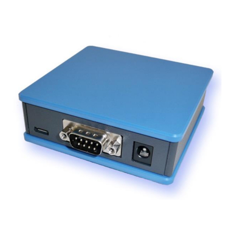
“4.0 Shell” enclosure with PG screw type connection:
Enclosure with optional “M8” connectors:
Page: 3 Version 2021-05-06

Inside, shown with optional LTE mobile data stick and optional industrial grade USB stick:
4.2. START AND STOP OPERATION
The Avisaro 4.0 starts with operation right after power on if an USB stick is inserted. Also, after
re-inserting a USB stick, the operation starts automatically.
4.3. LED BLINK-CODES
There is one multicolor LED to signal states of the Avisaro device.
Code
What is means
Action
Green & blue fading
All is fine
Idle state, no data arriving
None
Green flashing
Data are coming in
(RS232, CAN interface)1)
Red flashing
No USB stick
or button was pushed
Insert USB stick
Or press button again
Version 2021-05-06 Page: 4

1) On analog loggers (e.g. 4…20mA) and similar interfaces, data are read continuously, thus no green
flashing is shown
4.4. REAL-TIME CLOCK
A battery buffered internal real time clock is available for time stamping data, start and stop network
upload and others controls. The battery is a rechargeable “memo-buf” cell - specifically designed for
RTC operations. During regular operation, the battery is recharged over a 48h period. During
non-operating times (= supply power off) , the date and time settings are maintained.
If the Avisaro device is networked, a network time server (SNTP) can be used to set time and date
automatically.
If a Avisaro GPS receiver is connected, the RTC can be set using satelite time.
It is possible to define time zones settings.
4.5. CONCEPT OF OPERATION
The Avisaro 4.0 is divided into sections:
Data is received through an “Interface” and then forwarded to the “Data Processing” section. All
formatting happens here and then data is forwarded to the “Data Endpoint”.
Page: 5 Version 2021-05-06

5. USB STORAGE STICK
5.1. FORMAT AND SIZE
Typically, the USB stick is not included in the scope of delivery. Thi
Regular USB memory sticks can be used:
Size: From 4 to 256 GByte
File system: Formatted as FAT or FAT32 (preferred)
5.2. CHOOSING THE RIGHT TYPE
Make sure to verify whether or not your application needs industrial grade USB storage - this is
typically a matter of temperature.
5.3. CHOOSING THE RIGHT SIZE
Larger USB memory sticks tend to become more sensitive to hardware faults. Thus, estimate the
amount of data per day, multiply by the number of days between USB stick reads and add some
slack.
If using the “ring buffer” setting, old data is deleted when the stick becomes full. “Full” means, if free
space drops below 100MB. Please note, that in this configuration, the last two days are not deleted.
Therefore, choose an USB stick which holds at least 2 days of data.
Version 2021-05-06 Page: 6

12. INTERFACE DESCRIPTION AND PIN LAYOUT
12.1. POWER
12.1.2. Power Supply “Avisaro 4.0 Shell”
Power supply parameter:
DC voltage, 12V to 32V
Recommended power: 3W
For the “4.0 Shell” version with cable glands, the power connection is done inside. This picture shows
the RS485 version - please refer to the interface drawing of the interface for your product:
Connector
Interface
Pin
Signal
Direction
8 pol
Power
and
Interface
1
GND
2
Vin (12V to 32V)
3-8
see below
Page: 7 Version 2021-05-06

12.1.2. M8 Connector
Standard M8 connector (male)
Connector
Interface
Pin
Signal
Direction
M8,
4 pol, male
Power
1
n.c.
2
GND
3
n.c
4
Supply Voltage
I
12.3. RS485 INTERFACE
This is an industry standard RS232 connection.
12.3.1. Default RS485 settings
Baudrate: 9.600
No of bits: 8
Parity bits: none
Stop bits: 1
Flow control: none
12.3.2. Signal levels
Max Input voltage range on signal pins: 0 to 5 V
Output level provided: 0V to 5V
Version 2021-05-06 Page: 8

12.3.3. 1x RS485 “Shell” ( “C42x77”, “G42x77” )
Connector
Interface
Pin
Signal
Direction
Screw Type
1st RS485
1
GND
Power & Signal
2
VCC (11..32V)
Power
3
RS485 B / D-
Bus
4
RS485 A / D+
Bus
5
n.c.
6
n.c.
7
n.c.
8
n.c.
Page: 9 Version 2021-05-06

11. CONFIGURATION: ‘PC COMPANION SOFTWARE’
The “PC Companion Software” is used to configure the Avisaro 4.0 Devices.
The software is available for download from the Avisaro homepage:
http://www.avisaro.de/de/40-PC-Software.html (German)
http://www.avisaro.com/en/40-ENG-PC-Software.html (English site)
There are two versions to download: “Install” and “Direct start” – the first runs an installer which
requires administrative rights on the PC, the second one can be started without an install process. If
unsure, check with your IT department which version to download.
11.1. SOFTWARE INSTALLATION (“SECURITY WARNING”)
Windows warns the user before installing or using software downloaded from the Internet. So if you
click on “Avisaro_40_Companion_v2.31_Setup.exe”, the warning will occur:
After a click on “More Info”, the box shows:
Select “Run anyway” to continue.
11.2. DRIVER INSTALLATION
If you connect the Avisaro Device to the PC using a Micro USB cable, a virtual COM port driver is
installed. If this driver does not install automatically, you can download and install this manually:
http://www.avisaro.de/de/40-PC-Treiber.html (German site)
http://www.avisaro.com/en/40-ENG-PC-Driver.html (English site)
Version 2021-05-06 Page: 10

11.3. INITIAL SET-UP
After starting the companion software, the virtual COM port number needs to be entered. You can
find this number in the Windows “Device Manager”.
This setting is stored for future use.
Click on ‘open COM port’ – which will turn green if successful. You can use the “check” button to
verify that the connection is alive.
You can use the “Check” button to verify the connection to the Avisaro Device. It should light up
green when clicked.
The baudrate setting for “if connected through real RS22.. “ can be ignored. This setting is used only
in special projects and not scope of this document.
All settings are deactivated if there is no Avisaro Device attached.
11.4. USING THE PC COMPANION TOOL
Click on “Write Config” to transmit changes in the PC tool to the Avisaro device. Click on “Read
Config” to display the currently stored values (if you navigate between options, the latest settings are
read of course automatically).
Most settings become active after reboot. This can be done in Commands ⇨Device Control: Reboot
Device
Page: 11 Version 2021-05-06

11.8. INTERFACES ⇨ (1ST) RS232/RS485 AND (2ND) RS232/RS485
The 1st and 2nd RS232/RS485 settings are identical.
The Baudrate settings follow typical industry settings and need to match the target application.
The Protocoll settings are as follows:
“Regular RS232”: data are passed on with no further interpretation.
“Char Terminated”: data are grouped as one block until the ‘end of line’ identifier is reached.
“GPS(uBlox)”: the NMEA strings are treated as one block of data.
The Collect Time defines a time period in ms for how long data are collected into one block. A ‘0’ lets
the logger process each received character one at a time. A good value is 100ms - thus the logger
collects for 100ms data before starting to process them.
The End of Line identifier defines the character which ends one block of data. This is only active with
the “Char Terminated” protocol.
11.10. DATA PROCESSING ⇨ SERIAL DATA (GENERIC)
This configuration defines how RS232/RS485 data are processed. Choose the type of formatting and
the target.
Version 2021-05-06 Page: 12

Storage format defines how RS232 data are stored:
“Off”: data are not stored
“Raw data”: data are stored without any formatting as they come from the interface
“Timestamp+ASCII”: data are stored with a leading timestamp followed by the data. This works well
for ASCII/Text data, but not good for binary data.
“Tmestamp+HEX”: data are stored with a leading timestamp followed by the data as HEX format. This
works well for binary data.
11.12. DATA ENDPOINTS ⇨ USB STICK
This setting controls the file handling on the USB memory stick.
Page: 13 Version 2021-05-06

“Create new file policy”: “1st file”
Off
No data storage, all data are discarded
One file
All data are stored in one big file.
Every new start
Every hour
A new file is created every hour.
The files are named “yymmddhh.txt”
Every hour with ringbuffer
A new file is created every hour. If storage space is
consumed, the oldest file is deleted. Note:
●There is a hysteresis: if free storage drops
below 100 MB, old files are deleted until
500 MB are free again
●The last two days from today backward are
not deleted. This is for malfunction security:
This assumes that the stick could hold at
least 2 days of data - if not, this is a
configuration error.
Every day
A new file is created day at midnight.
The files are named “yyyymmdd.txt”
Version 2021-05-06 Page: 14

Page: 15 Version 2021-05-06

14. FIRMWARE UPDATE
We strongly recommend to do a firmware update only if needed. There is a potential risk of a failed
update process to cause a dead device which can only be recovered by sending it to Avisaro service.
Good reason for an update is a known bug repair or an additional feature.
There are three ways to update the firmware of the Avisaro 4.0 family:
1) Via USB Stick
If the Avisaro 4.0 product has a USB Host port, a new firmware can be uploaded using a USB
stick. See details below.
2) Via PC Companion software
If the Avisaro 4.0 product is connected to a PC via USB cable, the firmware can be updated
using the PC companion software. See details below.
3) Via Remote Update
For selected products, a remote firmware update via FTP server / Internet is provided.
See paragraph “Remote Firmware Update” for details.
The latest firmware version can be found online: http://www.avisaro.de/de/40-Firmware.html
14.1. FIRMWARE UPDATE VIA USB STICK
Instructions:
●Download the latest version of the firmware from the link posted above
●Unpack the *.zip file to retrieve the “avi40up.bin” file
●Copy the file onto a USB stick in the root directory
●Power up the Avisaro data logger
●Insert the USB stick
○After a few seconds, the LED flashes red (the firmware is loaded)
○After about 30 seconds, the LED flashes white (critical update phase, to not
interrupt)
○The logger reboots and starts again to show a green LED
●The firmware update file is deleted from the USB stick when finished - this is to avoid
accidentally a restart of the process.
●Done !
Version 2021-05-06 Page: 16

Warning:
●Ensure stable and sufficient power supply during this process. There is a risk that the device
becomes unusable if there is a power failure during the process. Those broken devices needs
to be send in to Avisaro for repair.
Background:
●The configuration remains - if not stated otherwise - the same. Thus, all settings stay the
same after a firmware update
14.2. FIRMWARE UPDATE VIA PC SOFTWARE
See paragraph “PC Companion Software” for details.
14.3. FIRMWARE UPDATE VIA FTP SERVER /INTERNET
See paragraph “Remote Firmware Update” for details.
Page: 17 Version 2021-05-06
This manual suits for next models
3
Table of contents
Other Avisaro Data Logger manuals

Avisaro
Avisaro 4.0 Silver User manual

Avisaro
Avisaro M49924 User manual

Avisaro
Avisaro 4.0 Series User manual

Avisaro
Avisaro M47724 User manual

Avisaro
Avisaro 4.0 Series User manual

Avisaro
Avisaro M49076 User manual

Avisaro
Avisaro 4.0 Series User manual

Avisaro
Avisaro M41076 User manual

Avisaro
Avisaro 4.0 Sky User manual

Avisaro
Avisaro 4.0 Series User manual