Avisaro RS232 User manual

Jump to: Table of Content
2021/06/16
Page : 2
1TABLE OF CONTENT
2 This document ......................................................................................................................................4
2.1 Location.........................................................................................................................................4
2.2 Other documents..........................................................................................................................4
2.3 Language Versions ........................................................................................................................4
3 Enclosure and User Controls.................................................................................................................5
3.1 Start and stop operation...............................................................................................................5
3.2 LED Blink-Codes.............................................................................................................................5
3.3 Real-Time Clock.............................................................................................................................5
3.4 Enclosure “4.0 Sky” with D-Sub connector...................................................................................6
4 USB Storage Stick..................................................................................................................................7
4.1 Filesystem and Storage size ..........................................................................................................7
4.2 Choosing the right memory stick..................................................................................................7
5 Interface description and Pin Layout....................................................................................................8
5.1 Micro-USB Client...........................................................................................................................8
5.2 RS232 Interface.............................................................................................................................8
5.2.1 Default RS232 settings ..........................................................................................................8
5.2.2 Signal levels...........................................................................................................................8
5.2.3 D-Sub Connector...................................................................................................................8
6 Configuration: ‘PC Companion Software’ ...........................................................................................10
6.1 How to configure Avisaro “Series 4.0” products ........................................................................10
6.2 Concept of operation..................................................................................................................10
6.3 Detailed documentation.............................................................................................................10
6.4 “PC Companion Software” Installation.......................................................................................11
6.5 Driver installation........................................................................................................................11
6.6 Initial Set-Up ...............................................................................................................................12
6.7 Using the PC Companion Tool.....................................................................................................12
7 Declarations ........................................................................................................................................13
7.1 EC/EU Declaration of Conformity ...............................................................................................13
8 Contact and Support...........................................................................................................................14
Jump to: Table of Content
2021/06/16
Page : 4
2THIS DOCUMENT
2.1 LOCATION
Check for the latest document version the following link:
German site: https://www.avisaro.de/de/40-Datenlogger-Sky-1xRS232-DSUB.html
English site: https://www.avisaro.com/en/40-Data-Logger-Sky-1xRS232-DSub.html
2.2 OTHER DOCUMENTS
“Technical User Manual 4.0” contains all of this and more information.
Link: https://www.avisaro.com/en/40-ENG-Documentation.html
2.3 LANGUAGE VERSIONS
This document is available in English version only

Jump to: Table of Content
2021/06/16
Page: 5
3ENCLOSURE AND USER CONTROLS
3.1 START AND STOP OPERATION
The Avisaro 4.0 starts with operation right after power on if an USB stick is inserted. Also, after re-
inserting a USB stick, the operation starts automatically.
3.2 LED BLINK-CODES
There is one multicolor LED to signal states of the Avisaro device.
Code
What is means
Action
Green & blue fading
All is fine
Idle state, no data arriving
None
Green flashing
Data are coming in
(RS232, CAN interface)1)
None
Yello constant
All is fine, USB stick is
checked after mounting
None
Red flashing
No USB stick
or button was pushed
Insert USB stick
Or press button again
1) On analog loggers (e.g. 4…20mA) and similar interfaces, data are read continuously, thus no green
flashing is shown
3.3 REAL-TIME CLOCK
A battery buffered internal real time clock is available for time stamping data, start and stop network
upload and others controls. The battery is a rechargeable “memo-buf” cell - specifically designed for RTC
operations. During regular operation, the battery is recharged over a 48h period. During non-operating
times (= supply power off) , the date and time settings are maintained.
If the Avisaro device is networked, a network time server (SNTP) can be used to set time and date
automatically.
If a Avisaro GPS receiver is connected, the RTC can be set using satelite time.
It is possible to define time zones settings.

Jump to: Table of Content
2021/06/16
Page : 6
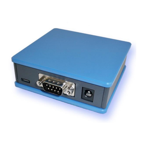
3.4 ENCLOSURE “4.0 SKY”WITH D-SUB CONNECTOR
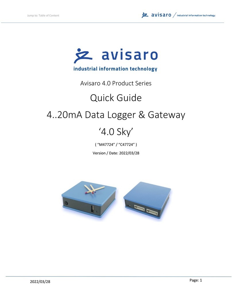
Front with slot for USB stick. Matches are shown
just for size reference:
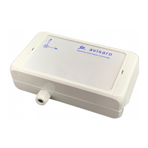
Reverse side shows D-Sub connector for data and
barrel connector for power. The micro USB port is
for configuration only:
Optional, a DIN rail fitting is available:

Jump to: Table of Content
2021/06/16
Page: 7
4USB STORAGE STICK
4.1 FILESYSTEM AND STORAGE SIZE
Commercially available USB 2.0 / 3.0 memory sticks can be used. It is recommended to exclude branded
products - no "promotional items" with your own logo imprint.
There are no speed requirements. Memory sticks that are advertised as particularly fast offer no (!)
advantage in the Avisaro data logger. Typically these optimizations are designed for cameras etc..
Memory sizes from 4 to 256 GByte are supported. As file system FAT or FAT32 (preferred) is used. NTSF
or others are not supported.
Memory sticks are typically not in the scope of delivery - each application typically has different
requirements.
4.2 CHOOSING THE RIGHT MEMORY STICK
For industrial use, special parameters may have to be observed.
The temperature range should be considered. There are "industrial grade" memory sticks available -
often designed as "SLC" version - which are also suitable for harsh environments.
The mechanical dimension should also be considered. It is disadvantageous if the stick protrudes openly
from the housing and could be knocked off. In this case short sticks are recommended. If the logger is
installed protected, then a longer stick is easier to use.
The appropriate memory size also depends on the intended use. Due to the technology, memory sticks
with an extremely high capacity are typically less robust than smaller memory sizes. The loggers have a
"ring memory" that can be optionally activated. If the memory stick becomes full (approx. less than
100MB free memory) the oldest files are deleted - this is a useful setting for some applications.

Jump to: Table of Content
2021/06/16
Page : 8
5INTERFACE DESCRIPTION AND PIN LAYOUT
5.1 MICRO-USB CLIENT
The Micro-USB client interface is used for configuration only.
Most Avisaro devices are powered through the Mico-USB client port, however only for configuration. A
stable regular operation is not guaranteed. Use the regular power supply for normal operation.
A “Micro USB” cable is used. As those cable are widely available, this cable is not part of scope of
delivery to avoid electronic waste.
5.2 RS232 INTERFACE
This is an industry standard RS232 connection.
5.2.1 Default RS232 settings
Those are the default settings:
Baudrate
9600
No of bits
8
Parity bits
none
Stop bits
1
Flow control
none
5.2.2 Signal levels
Max Input voltage range on signal pins: -24 to 24 V
Output level provided: -5V to 5V
5.2.3 D-Sub Connector
Industry standard SubD-9 connector (male)

Jump to: Table of Content
2021/06/16
Page: 9
Connector
Interface
Pin
Signal
Direction
D-Sub,
9 pol, male
1st RS232
1
n.c. (optional DCD)
2
RxD - Data
in
3
TxD - Data
out
4
n.c. (optional DTR)
5
GND
Power & Signal
6
n.c. (optional DSR)
7
RTS - Signal
out
8
CTS - Signal
in
9
n.c. (optional: VCC (6..32V))
Power
Supply voltage does not carry an output voltage –thus if the device is powered via barrel connector, Pin
9 does not show the input voltage (internal diode). This is for security reason. If needed, Avisaro can
modify the device such that this pin can be used to power other devices.

Jump to: Table of Content
2021/06/16
Page : 10
6CONFIGURATION:‘PC COMPANION SOFTWARE’
6.1 HOW TO CONFIGURE AVISARO “SERIES 4.0” PRODUCTS
The basic principle of how to configure the Avisaro “Series 4.0” products is:
1) Download and install the “Avisaro PC Companion Software”.
2) Connect the Avisaro device via USB cable.
3) Choose the correct COM port and click on “connect”.
4) The software presents all the settings you can make and guides you to avoid conflicting
configurations.
5) Click on “save configuration” to store changes in the Avisaro device.
6) Reboot the Avisaro Device so that the new configuration takes effect.
Details are described further down in this document.
6.2 CONCEPT OF OPERATION
The Avisaro 4.0 is divided into sections:
Data are received through an “Interface” and then forwarded to the “Data Processing” section. All
formatting happens here and then data is forwarded to the “Data Endpoint”.
6.3 DETAILED DOCUMENTATION
This current document shows only selected parts of the full “Avisaro PC Companion Software”user
manual. The motivation is to keep this document as compact as possible.
Please find the extensive “Avisaro PC Companion Software” document in the support section of the
Avisaro website:
German: https://www.avisaro.de/de/40_Dokumentation.html
English: https://www.avisaro.com/en/40-ENG-Documentation.html

Jump to: Table of Content
2021/06/16
Page: 11
6.4 “PC COMPANION SOFTWARE”INSTALLATION
Windows warns the user before installing or using software downloaded from the Internet. So if you
click on “Avisaro_40_Companion_v2.31_Setup.exe”, the warning will occur:
After a click on “More Info”, the box shows:
Select “Run anyway” to continue.
6.5 DRIVER INSTALLATION
If you connect the Avisaro Device to the PC using a Micro USB cable, a virtual COM port driver is
installed. If this driver does not install automatically, you can download and install this manually:
http://www.avisaro.de/de/40-PC-Treiber.html (German site)
http://www.avisaro.com/en/40-ENG-PC-Driver.html (English site)

Jump to: Table of Content
2021/06/16
Page : 12
6.6 INITIAL SET-UP
After starting the companion software, the
virtual COM port number needs to be entered.
You can find this number in the Windows
“Device Manager”.
This setting is stored for future use.
Click on ‘open COM port’ – which will turn green
if successful. You can use the “check” button to
verify that the connection is alive.
You can use the “Check” button to verify the
connection to the Avisaro Device. It should light
up green when clicked.
The baudrate setting for “if connected through
real RS22.. “ can be ignored. This setting is used
only in special projects and not scope of this
document.
All settings are deactivated if there is no Avisaro Device attached.
6.7 USING THE PC COMPANION TOOL
Click on “Write Config” to transmit changes in the PC tool to the Avisaro device. Click on “Read Config”
to display the currently stored values (if you navigate between options, the latest settings are read of
course automatically).
Most settings become active only after reboot. This can be done in Commands ⇨Device Control:
Reboot Device.
This manual suits for next models
7
Table of contents
Other Avisaro Data Logger manuals

Avisaro
Avisaro RS485 User manual

Avisaro
Avisaro 4.0 Series User manual

Avisaro
Avisaro M41076 User manual

Avisaro
Avisaro M49924 User manual

Avisaro
Avisaro 4.0 Silver User manual

Avisaro
Avisaro M47724 User manual

Avisaro
Avisaro M49076 User manual

Avisaro
Avisaro 4.0 Series User manual

Avisaro
Avisaro 4.0 Series User manual

Avisaro
Avisaro 4.0 Sky User manual
Popular Data Logger manuals by other brands

Sea-Bird Scientific
Sea-Bird Scientific SBE 25plus Sealogger CTD Basic user manual

MadgeTech
MadgeTech Shock101-100 Product user guide

Ecotech
Ecotech WinAQMS user manual

Circutor
Circutor PV-Monitor-M instruction manual

peoplenet
peoplenet eDriver Logs Quick reference guide

Hach
Hach FL900 Series Basic user manual