Avlite AV-C310-ILA Supplement

Version 3.1
AV-C310-ILA & AV-C410-ILAB
Solar Powered
ICAO Low Intensity Obstruction Light Type
A/B Installation & Service Manual

AV-C310-ILA & AV-C410-ILAB
Solar Powered ICAO Low Intensity Obstruction Light Type A/B
Latest products and information available at www.avlite.com
2
V
ersion No. Description Date Approved
1.0 Manual launch March 2012
A
.Dixon
2.0 Product Code Change October 2012 J. Dore
2.4 GSM Option October 2013 S. Turner
2.5 Update: Torque Setting February 2014 P. Raine
y
3.0 Update Installation July 2016 W. Evans
3.1 Update: Dip Switch Information, IR Controller
settin
g
s, Remove Flash Code Table.
September 2017
A
. Dixon

AV-C310-ILA & AV-C410-ILAB
Solar Powered ICAO Low Intensity Obstruction Light Type A/B
Latest products and information available at www.avlite.com
3
Introduction..........................................................................................Page 4
Operating Principle .............................................................................Page 4
Technology...........................................................................................Page 4
AV-C310-ILA& AV-C410-ILABModel ....................................................Page 5
AV-C310-ILA& AV-C410-ILAB Optional Configurations .....................................
Page 8
Activation ..............................................................................................Page 9
Installation............................................................................................Page 10
Selecting an Intensity & Flash Code..................................................Page 11
Selecting an Operation Mode………......................................................
Page 11
Selecting an ICAO LIOL Intensity A or B.................................................
Page 11
Lantern Status LED’s ………..............................................................Page 12
Optional IR Remote Control ..............................................................Page 13
Avlite IR Controller / Universal Remote Compatibility ................Page 13
IR Controller Functions...............................................................Page 14
Test Mode / Configure ...............................................................
Page 14
Normal Operation .......................................................................
Page 14
Lux..............................................................................................
Page 14
Error/Acknowledge Indication.....................................................
Page 16
Hibernation Mode (Advanced Users) .........................................
Page 17
Storage Mode (Advanced Users) ...............................................
Page 19
Set Operation Mode ....................................................................
Page 19
Optional GSM Monitoring: AV-C410-ILABModel ..............................Page 20
Maintenance and Servicing ...............................................................Page 21
Replacing the Battery .................................................................Page 21
Long Term Battery Storage ........................................................Page 22
Solar Panel Replacement...........................................................Page 23
How to Change the Regulator ....................................................Page 24
Trouble Shooting ................................................................................Page 25
AV-SB-10 Solar Booster .....................................................................Page 26
Solar Booster Installation Procedure......................................................
Page 28
Notes…………………...........................................................................Page 29
Avlite Light Warranty..........................................................................Page 30
Table of Contents

AV-C310-ILA & AV-C410-ILAB
Solar Powered ICAO Low Intensity Obstruction Light Type A/B
Latest products and information available at www.avlite.com
4
Congratulations! By choosing to purchase an Avlite light, you have become the
owner of one of the most advanced solar LED airfield lights in the world.
Since 2004 Avlite Systems has been designing and manufacturing the most advanced navigation
aids. Particular care has been taken to ensure your light gives years of trouble free service.
As a commitment to producing the highest quality products for our customers, Avlite has been
independently certified as complying with the requirements of ISO 9001:2008 quality management
system.
By taking a few moments to browse through this booklet, you will become familiar with the versatility of
your light, and be able to maximise its operating function.
Please remember to complete the Avlite warranty registration card accompanying your light.
The solar module of the light converts sunlight to an electrical current that is used to charge the
battery. The battery provides power to operate the light at night.
The flasher unit has very low current requirements. A microprocessor drives an ultra-bright
LED through a DC/DC converter, which enables the LEDs to operate within the manufacturer’s
specifications. The battery is protected from over-charging within the circuit to ensure maximum
battery life.
On darkness, the microprocessor will initiate a program check and after approximately 1 minute will
turn on.
Avlite Systems is a world-class solar lighting systems manufacturer with a proven
reputation for rapid, innovative, and agile technology solutions designed specifically
for defense, government, civil and humanitarian aid operations in the most remote,
toughest environments.
Electronics
Avlite employs leading in-house electronic engineers in the design and development of software and
related circuitry. All individual electronic components are sourced directly by Avlite procurement staff
ensuring that only the highest quality components are used in our products.
LED Technology
All aviation lights use the latest advancements in LED (Light Emitting Diode) technology as a light
source. The major advantage of LEDs over traditional light sources is well established in that they
typically have an operational life in excess of 100,000 hours, resulting in substantial savings to
maintenance and servicing costs.
Precision Construction
Commitment to investing in the design and construction of injection-moulded parts including optic
lenses, light bases and a range of other components ensures that all Avlite products are of a
consistent and superior quality.
Optical Performance
Avlite manufactures a range of aviation LED lenses moulded from multi-cavity dies. The company has
superior in-house lens manufacturing capabilities to support outstanding optical performance.
Award-winning, Patented Technology
Several United States and Australian patent registrations are held on Avlite’s range of innovative
designs, with other regional patents pending in Canada, United Kingdom and Europe.
Introduction
Operating Principle
Technology

AV-C310-ILA & AV-C410-ILAB
Solar Powered ICAO Low Intensity Obstruction Light Type A/B
Latest products and information available at www.avlite.com
5
AV‐C310‐ILAModel
Avlite’s Solar powered ICAO LIOL available as Type A only on the C310 chassis, and as Type A
and B on the C410 chassis is a robust, completely self-contained solar powered LED obstruction
light.
The AV-C310-ILA model has four 3 watt (12watt total) premium-grade solar modules
integrated into the solar chassis, and mounted to collect sunlight at all angles. This unit
complies with the requirements for ICAO Low Intensity Obstruction Lights Type A 2009
Standard.
The AV-C410-ILAB model has four larger 5watt panels (20 watt total) for use in areas of lower
sunlight to maximise solar collection. This unit complies with the requirements for ICAO Low
Intensity Obstruction Lights Type A & B 2009 Standard.
The solar array charges an internal battery during daylight hours, and at dusk the light will
automatically begin operation.
The rugged design of this self-contained light ensures up to 12 years of reliable service with
minimal ongoing maintenance.
SingleLEDOptic
Robust7‐stage
powder‐coated
aluminiumchassis
withrubberextruded
corners
User‐replaceable
multicrystalline
solarmodules
ensuremaximumlight
collectiontocharge
thebattery
Internal24Ah
battery
Internal12Ah
battery
AV‐C410‐ILAB
Model
4hole200mmbolt
patternforeaseof
installation
Figure 1.
AV-C310-ILA & AV-C410-ILAB Model

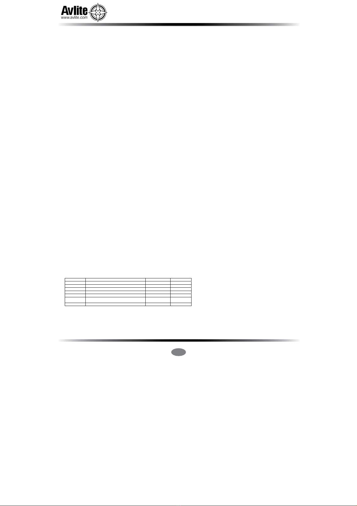
SPECIFICATIONS•* AV‐C310 AV‐C410
LightCharacteristics
Light Source AstestedAV‐OL‐ILA‐12‐RLED AstestedAV‐OL‐ILAB‐12‐R LED
PeakIntensity(cd)† ComplieswithICAOLIOLA2009 ComplieswithICAOLIOLA&B2009
HorizontalOutput(degrees) 360 360
VerticalDivergence(degrees) +4to+13 +4to+13
ReflectorType SingleLEDOptic SingleLEDOptic
LEDLifeExpectancy(hours) >100,000 >100,000
ElectricalCharacteristics
CurrentDraw(mA) Steady‐on:39forLIOLA
Steady‐on:39forLIOLA
CircuitProtection Integrated Integrated
OperatingVoltage(V) 12 12
TemperatureRange ‐40to80°C ‐40to80°C
SolarCharacteristics
SolarModuleType Monocrystalline Monocrystalline
Output (watts) 12(4x3watt) 20(4x 5watt)
SolarModuleEfficiency (%) 14 14
ChargingRegulation Microprocessorcontrolled
Microprocessor controlled
PowerSupply
BatteryType SLA(SealedLeadAcid) SLA(SealedLeadAcid)
BatteryCapacity(Ah) 12 24
NominalVoltage(V) 12 12
TypicalAutonomy(nights) Steady‐on:>20
Steady‐on:>40
Approx.dailyinsolationtomaintain
fullautonomy(kWh/m
2
)
PhysicalCharacteristics
2.2 1.4
0.7(withSolarBooster™)
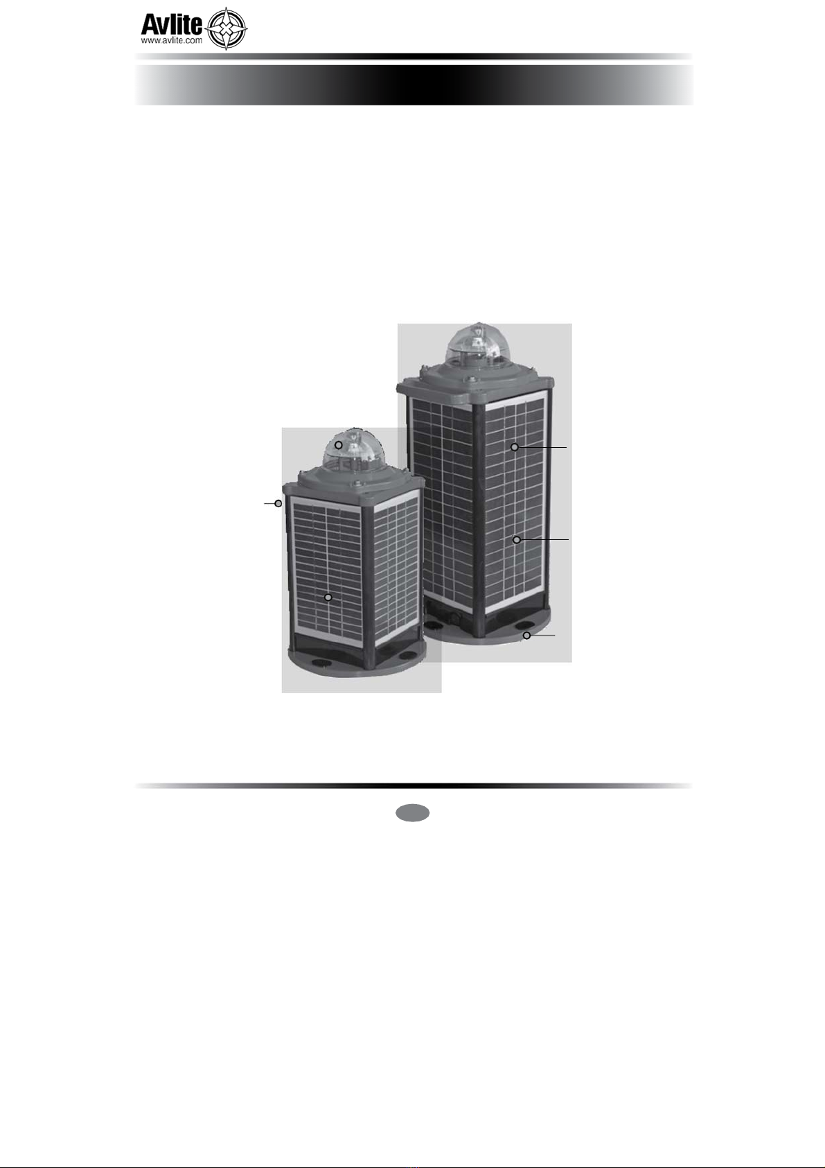
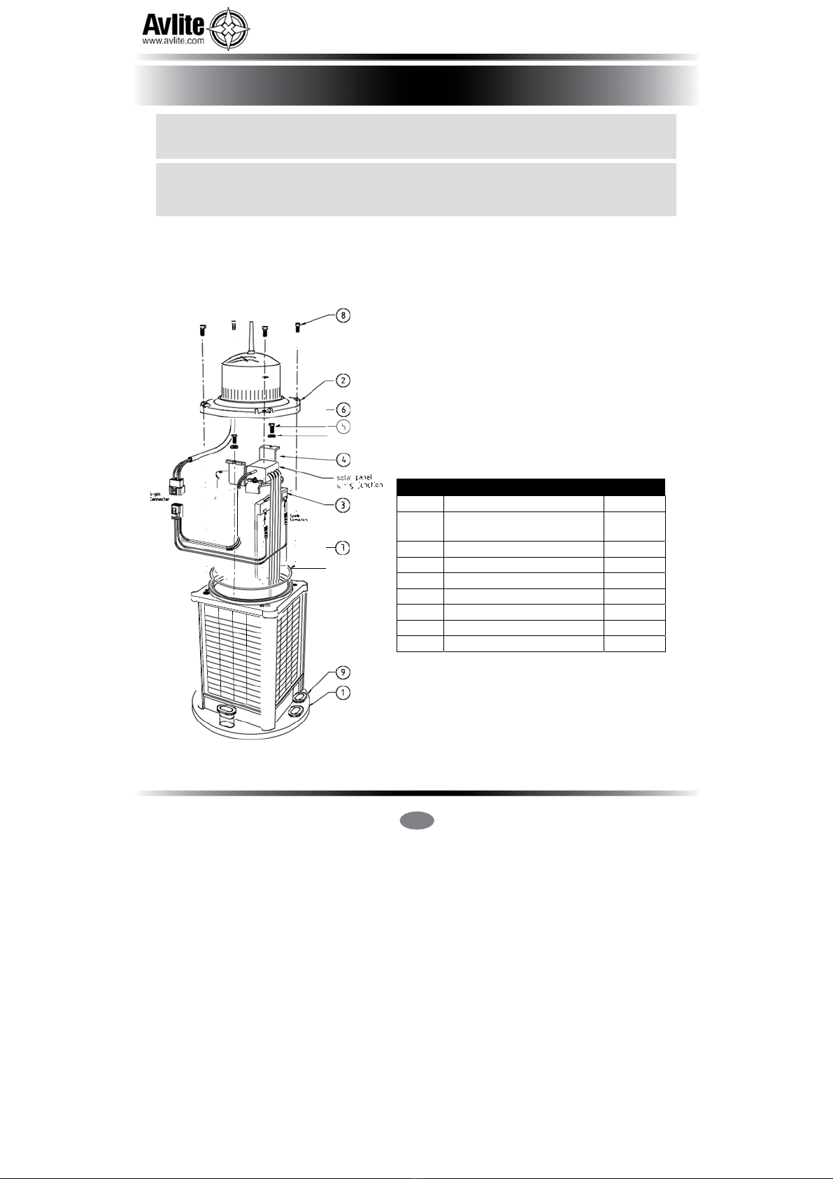
BodyMaterial 7‐stagepowder‐coatedaluminium 7‐stagepowder‐coatedaluminium
LensMaterial LEXAN® Polycarbonate
–UVstabilized
LEXAN®Polycarbonate
–
UVstabilized
LensDiameter(mm/inches) 107/4¼ 107/4¼
LensDesign SingleLEDOptic SingleLEDOptic
Mounting 4x17mmholeson200mmPCD 4x17mmholeson200mmPCD
Height(mm/inches) 375/14¾ 470/18½
Width(mm/inches) 233/9¼ 233/9¼
Mass(kg/lbs) 9.1/20 13.9/30½
ProductLifeExpectancy Upto12years Upto12years
EnvironmentalFactors
Humidity 0to100%,MIL‐STD‐810F 0to100%,MIL‐STD‐810F
Icing 22kgpersquareinch 22kgpersquare inch
WindSpeed Upto160kph Upto160kph
Shock
MIL‐STD‐202G,TestConditionH,
Method213B
Vibration MIL‐STD202G,TestConditionH,
Method204
MIL‐STD‐202G,TestConditionH,
Method213B
MIL‐STD202G,TestConditionH,
Method204
Certifications
CE EN61000‐6‐3:1997.EN61000‐6‐1:1997 EN61000‐6‐3:1997. EN61000‐6‐1:1997
QualityAssurance ISO9001:2008 ISO9001:2008
ICAO LowIntensityObstructionLightTypeALowIntensityObstructionLightTypeA
Waterproof IP68 IP68
IntellectualProperty
Trademarks AVLITE®isaregisteredtrademarkof
AvliteSystems
AVLITE®isaregisteredtrademarkof
AvliteSystems
Warranty*
3yearwarranty 3yearwarranty
Options Available
GPSSynchronisation
•IRLED
•
ExternalON/OFFSwitch
•
ExternalBatteryChargingPort
•
GSMCell‐PhoneMonitoring
•
GPSSynchronisation
•
IRLED
•
ExternalON/OFFSwitch
•
ExternalBatteryChargingPort
•
SolarBooster™
•
Specifications
subject
t
o
c
hange
or
v
ariation
without
notice
*
Subject
t
o
st
andar
d
t
erms
and
conditions
†
Int
ensity
setting
subject
t
o
solar
a
vailability

AV-C310-ILA& AV-C410
Solar Powered ICAO Low Intensity Obstruction Light Type A
Latest products and information available at www.avlite.com
7
Figure 2. AV-C310-ILA Model
Figure 3. AV-C410-ILAB Model

AV-C310-ILA& AV-C410
Solar Powered ICAO Low Intensity Obstruction Light Type A
Latest products and information available at www.avlite.com
8
Optional External ON/OFF Switch
The AV-C310-ILA and AV-C410-ILAB can be fitted with an external ON/OFF switch below the solar
panel at the base of the unit. The ON/OFF switch may be useful if the unit is only required for short
periods and is often being moved or needs to be stored often, and disconnecting the battery is not
viable.
Optional External Battery Charging Port
The AV-C310-ILA and AV-C410-ILAB can be fitted with an external battery charging port MIL-STD 2 Pin
connector. (ITT Cannon Part Number = MS3111E82P)
It is found below the solar panel at the base of the unit.
If the light is being stored for more than 1 month then the battery should be regularly recharged.
Please see ‘Long Term Battery Storage’ in the Maintenance & Servicing section of this manual.
You may purchase a suitable battery charger from Avlite
Or/
Use a connector that mates with the 2Pin connector on the unit.
Pin 1(A) = Battery Positive (+)
Pin 2 (B) = Battery Negative (-)
Optional IR Remote Control
The IR remote is used to communicate with Avlite lighting products that have an IR sensor fitted.
The remote control is used to control functions.
Optional GSM Cell-Phone Monitoring (AV-C410-ILAB Model only)
GSM Cell-Phone Monitoring enables operators to remotely monitor the status of their installations. The
system can also be configured to send out alarm SMS text messages to designated cellular telephone
numbers. Users can also have alarms and reports sent to designated email
addresses.
AV-C310-ILA& AV-C410 Optional Configurations

AV-C310-ILA& AV-C410
Solar Powered ICAO Low Intensity Obstruction Light Type A
Latest products and information available at www.avlite.com
9
The AV-C310-ILA and AV-C410-ILAB are designed as an obstruction light.
Light Operation
The light is activated by connecting the 4Pin battery connector inside the unit.
Please follow the steps under ‘Selecting an Operational Mode & Type’ section of the manual.
Figure 4. AV-C310/AV-C410-ILABSolar light components
Activation
Charging the Battery
New lights should be left in the sun for 1-2 days to ensure battery is charged before placing in
service. Please note, light will re-charge even when toggle switch is turned to ‘OFF’ position.
Preferred Installation Location
For best light performance, ensure solar modules are not covered and are in clear view of the
sky with no shadows.
Item Description Quantity
1 AV-C310/AV-C410 Base 1
2 AV-C410-ILAB Lens
Assembly
1
3 Battery 1
4 Battery Clamp 1
5 Washer M4 2
6 M4 Cap Screw 2
7 O-Ring, ID 145 x 4.0 1
8 Socket Head Screw M6 x 16 4
9 Mounting Insert 4

AV-C310-ILA& AV-C410
Solar Powered ICAO Low Intensity Obstruction Light Type A
Latest products and information available at www.avlite.com
10
Installing the Light Assembly to the Rubber Tile
The completed light – rubber tile assembly is to be mounted on a surface capable of supporting 20kg
minimum. Securing the rubber tile to the mounting surface is optional, however, Avlite recommend that
the tile be secured at a minimum of two points.
a. Insert bolts through the 4 x holes in the tile, entering from the bottom face (within the recess). It
may be necessary to use a rubber mallet to insert the bolts.
b. Fit the light over the bolts on the top face of the tile.
c. Install a penny washer and a Nylock nut on each bolt. Tighten nuts to finger-tightness.
d. Place the completed light assembly in the desired location.
e. Using a hammer, drive steel pegs through the holes in the corners of the rubber tile being careful
not to damage the solar panels.
Note: - Other means of securing the tile may be used where the mounting surface is not suited to the
use of steel pegs.
Installing the Light Assembly to the Frangible Stake Mount
The completed light - mount plate assembly is to be mounted on the stake in firm soil (not loose sand,
screenings or other unbound material).
a. Fit the light on the top of the mounting plate. Insert bolts through the four holes in the mount,
entering from the bottom. Install a penny washer and a Nylock nut on each bolt. Tighten Nylock
nuts.
b. Use a sledge hammer to drive the stake into the soil at the chosen location. Drive the stake down
until the bottom of the stake sleeve is at ground level.
c. Fit the boss of the mount plate into the shorter barrel of the frangible sleeve. Using a 6mm allen
key, tighten the socket head cap screw against the stake mount boss.
d. Fit the light and mounting plate assembly on top of the stake. The longer barrel of the frangible
sleeve should completely cover the stake sleeve. Using a 6mm allen key, tighten the bottom
socket head cap screws against the stake sleeve.
Installation

AV-C310-ILA& AV-C410
Solar Powered ICAO Low Intensity Obstruction Light Type A
Latest products and information available at www.avlite.com
11
1. Remove the four socket-head cap screws on the lens assembly.
2. Remove the flash adjustment plug from the underside of the light head.
3. The DIP switches control the Operational Modes and the Type of Obstruction Light required.
4. Operation mode can be set to either “Always On” or “Dusk to Dawn”
Always On = O (Important: Lights left in this state must only be used for short periods)
Dusk to Dawn = 1
5. ICAO Obstruction Light Type can be set to either Type A or Type B
Type B = N (Important: Type B operation is not recommended for the C310 chassis. Please only
select Type B for the C410 chassis)
Type A = 2
6. Set the Dip Switches to the required settings.
7. The Rotary Switches must be left on 0,0 to comply with the requirements for ICAO LIOL.
8. Replace the Flash Adjustment Bung.
9. Connect the 4Pin connector to power up the unit.
10. Place the top lens assembly back onto the light body and replace 4 x socket head screws. It is
recommended that the bolts for holding the light heads to the Solar Base units have a torque
setting applied of 3Nm for a satisfactory seal.
Applying a higher Torque setting is not recommended and may void warranty. If in doubt, please
contact your local Avlite representative.
Make sure the O-ring is fitted correctly in the O-ring groove.
11. The unit is now ready for normal operation, once placed in darkness.
12. To test place dark cover (towel or jacket) on top of light to activate sensor; light will come on.
The following diagrams indicate pulse settings:-
Fig 1 shows the typical settings used in the AV-C410-ILAB
Operation Mode = Dusk to Dawn and Type = B
Fig 2 shows the typical settings used in the AV-C310-ILA
Operation Mode = Dusk to Dawn and Type = A Fig 1 Fig 2
Selecting an Operation Mode & Type

AV-C310-ILA& AV-C410
Solar Powered ICAO Low Intensity Obstruction Light Type A
Latest products and information available at www.avlite.com
12
Two status LED’s on the main printed circuit board provide the operator with an indication of the
lantern status.
There is one red and one yellow status LED. The red status LED is used to indicate the health of the
lantern’s power system. The yellow status LED is used to indicate the operational status of the lantern.
These are positioned near the Flash Code Rotary Switches.
Use the table below to help determine operational status.
Yellow LED Lantern Status Lantern Comment
OFF Normal OFF Lantern is in Daylight and in Dusk till Dawn mode or in
Standby Mode
Flashing
ON 0.15 seconds
OFF 0.15
seconds
Normal
OFF
Light is activating and will turn on after detecting 30
seconds of continuous darkness.
Flashing
2 x quick flashes
every 2 seconds
(Heartbeat)
Normal
ON
Lantern is in Normal operating condition. It is not
connected to any GPS synchronisation.
Flashing
ON 1.5 seconds
OFF 1.5 seconds
Normal
ON Normal operating condition. Lantern is synchronised to
GPS-enabled lanterns.
Flashing
1 x quick flash
every 2 seconds
Normal
ON Lantern is ‘re-syncing’ with GPS.
The lantern re-sync’s with the GPS every 15 minutes.
Flashing
2 x quick
flashes every 11
seconds
Normal
ON
Lantern is a Hard Wire Synchronisation Slave.
Red LED Lantern Status Lantern Comment
OFF Normal
Normal Battery Voltage
Flashing once
every 1.6
seconds
Battery Voltage
is 12 – 12.5V
Battery Voltage is between 12 – 12.5V
Flashing twice
every 2 seconds
Battery Voltage
is 11.5 – 12V
Battery Voltage is between 11.5 – 12V
Flashing 3 x
times every 2
seconds
Battery Voltage
is 10.0 – 11.5V
Battery Voltage is between 10.0 – 11.5V
Flashing 4 x
times every 2.5
seconds
Battery Voltage
is <10.0V
Battery Voltage is less than 10.0V
Fixed-on
Flat Battery
(<10V)
OFF
Flat Battery cut-off is now operational and the lantern
will be off. Battery must receive charge (above 12V) and
lantern must see daylight for at least 1 minute before
resuming normal operation.
Flashing
ON 1.5 seconds
OFF 1.5 seconds
Battery Voltage
is above 13.5V
Battery Voltage is above 13.5V. this may indicate a
problem with the solar regulator.
Lantern Status

AV-C310-ILA& AV-C410
Solar Powered ICAO Low Intensity Obstruction Light Type A
Latest products and information available at www.avlite.com
13
The IR remote is used to communicate with Avlite lighting products that have
an IR sensor fitted. The remote control is used for the following functions:
• Operational Mode: sets the Operational Mode, Always On, Dusk to Dawn
or Standby Modes.
• Ambient Light Thresholds: read the current light thresholds, configure new
ambient light thresholds.
• Perform a battery health check.
On receiving a valid key signal from the IR Remote, the light will flash once.
The user should wait until the light responds to each keypress before pressing
another key. If there is no response to the keypress after 3 seconds, it has not
been detected by the light and the key can be pressed again.
If an invalid key is detected, the light will flash quickly 5 times. In this case, the
command will have to be restarted.
If you lose your Avlite IR Controller, the following Universal Remote Controller has been tested for
compatibility: RCA Type RCR312WR programmed for Phillips TV Type Code 10054
Avlite Key Universal
Remote Key
T Power
1 1
2 2
3 3
4 4
5 5
6 6
7 7
8 8
9 9
0 0
R Channel+
L Mute
FC Volume+
I Volume-
B Channel-
Optional IR Remote Control
Avlite IR Controller / Universal Remote Compatibility
Test/Configure
T/C
FC I B

Latest products and information available at www.avlite.com
14
AV-C310-ILA& AV-C410
Solar Powered ICAO Low Intensity Obstruction Light Type A
Test Mode / Configure
Pressing the T/C button for up to 5 seconds places the light in Test Mode. The light will flash once in
response to the T/C button being pressed and then turn off.
Normal Operation
The light will return to normal operation once it has not detected a valid key press for 15 seconds. The
light will flash once to indicate it is returning to normal operation.
Lux
This key sets the ambient light threshold levels.
The format is
Where ‘x’ is the desired setting from the table below.
Level Sunset
(Dusk)
Sunrise
(Dawn)
1 64 100
2* 100 150
3 150 240
4 240 370
5 370 600
* Default / Factory Preset
There are 5 programmable lux levels which are set together for the sunset and sunrise transitions.
Example key sequence:
Assume the current Lux settings are at the factory preset values of 2.
This sets the ambient light level to be lower than the default 100 lux. The light will turn on when its
surroundings are darker.
The light responds by acknowledgement with a long flash.
IR Controller Functions
L
L
L

Latest products and information available at www.avlite.com
15
AV-C310-ILA& AV-C410
Solar Powered ICAO Low Intensity Obstruction Light Type A
Error/Acknowledge Indication
If the key sequence is invalid, or an out of bounds value is attempted to be set, the light flashes 5 times
for 1 second. (The command then needs to be sent from the start.)
Example key sequence: (Set the intensity level to 5 – undefined.)
The light flashes 5 times for 1 second.
When a key sequence has been entered successfully the light will respond acknowledgement with a
long 1 second flash.
Hibernation Mode - only available with GPS option fitted (Advanced users)
For situations where the lantern is put into storage for a known period, the IR Remote control can be
used to configure the lantern into Hibernation Mode for a user programmable date range.
Hibernation Mode maximises conservation of the battery power by disabling the light (will not activate
at night) and shutting off the GPS receiver to rely on the internal clock for date checking. The IR
sensor is still monitored in hibernation mode. Power consumption is only bettered by physically
disconnecting the battery supply.
Hibernation Mode is defined by a start date and end date that are programmed into the lantern via the
IR Remote Control.
Using the IR Remote Control
The lantern must be in Test Mode prior to pressing any of the following key sequences. However, the
lantern will return to Normal Operation if it has not detected a valid key press for a period of 15
seconds. When the lantern exits from Test Mode it will either enter Dusk to Dawn mode, Hibernation
mode, or Storage Mode, if enabled.

Latest products and information available at www.avlite.com
16
AV-C310-ILA& AV-C410
Solar Powered ICAO Low Intensity Obstruction Light Type A
Store Hibernation Mode Date Range
The following details the key press sequence that defines the start and end dates of Hibernation
Mode:
where ddmm is the numerical representation of the month (01=January, 08=August) of the start date,
and DDMM is the numerical representation of the end date.
e.g 9th of December is represented by the number sequence 0912.
The lantern will respond by flashing an acknowledge long flash.
This operation only stores the start & end dates into the lantern’s memory and Hibernation Mode still
must be enabled to commence its operation.
Enable Hibernation Mode
Pressing the following key sequence will enable (turn on) Hibernation Mode:
and the lantern will respond with a single flash.
The Lantern will take a new GPS reading, determine the calendar month, and then enter Hibernation
Mode and depending on the current calendar month setting will either Hibernate or enter Dusk-to-
Dawn mode.
By default, Hibernation mode is disabled. Note you can only use this command once a valid
hibernation start & end date has been stored in the lantern.
M
1
Test/Configure
T/C
FC I B

Latest products and information available at www.avlite.com
17
AV-C310-ILA& AV-C410
Solar Powered ICAO Low Intensity Obstruction Light Type A
Disable Hibernation / Hibernation Modes
Pressing the following key sequence will disable (turn off) both Hibernation Mode and Seasonal
Hibernation:
and the lantern will respond with a single long flash.
The Lantern will disable Hibernation Mode and enter Dusk-to-Dawn Mode.
Momentarily Wake Up from Hibernation Mode
Pressing the button will wake up the lantern.
At which point the lantern will remain awake for a further 15 secondss to process other commands
from the IR Controller. If no IR commands are received for a period of 15 seconds, the lantern will
return to Hibernation mode.
Read Stored Hibernation Dates
By pressing the following key sequence the lantern will respond with the stored start and end dates for
Hibernation:
Read Hibernation Mode Status
By pressing the following key sequence the lantern will respond with status of Hibernation mode.
Where:
• A single long flash = hibernation mode is Enabled
• Two quick flashes = hibernation mode is Disabled.
User Case Example: Configuring the lantern for Hibernation
In this example, we want the lantern to hibernate each year from Dec 10th, through to February 15th,
and the lantern is located inside a storage warehouse.
The required key sequence is:
Command IR Controller Key Press
Store the Hibernation
Date Range
L
I
1
0
1
2
1
5
0
2
T/C
Enable Hibernation
L
I
1
T/C
0
1
0

Latest products and information available at www.avlite.com
18
AV-C310-ILA& AV-C410
Solar Powered ICAO Low Intensity Obstruction Light Type A
Storage Mode (Advanced users)
For situations where the lantern is put into storage but with access to daylight, the IR Remote control
can be used to configure the lantern into Storage Mode.
This mode manually forces the lantern to turn off, but with access to daylight it will still charge battery
pack. However the lantern will not keep track of the date.
In Storage Mode, the GPS is disabled however the lantern will still respond to IR commands.
The lantern will automatically enter Storage Mode, if it is hibernating and it has not detected any light
for 20 hours.
Enter Storage Mode
By pressing the following key sequence the lantern will enter Storage Mode:
The lantern will leave storage mode when exposed to daylight or if the power switch is turned OFF and
ON again.
Set Operation Mode
There are three distinct lantern operational modes (always on, standby & Dusk to Dawn) which can
be set with the following key sequence
Always on
Standby Mode
Dusk to dawn
where
• Always on ignores the day light sensor.. The light sensor is disabled, however if 20 continuous
hours of darkness is detected, the lantern will enable Storage mode.
• Standby only disables the light with no additional power saving measures. (GPS is on)
• Dusk to Dawn the lantern turns on when darkness has been detected by the light sensor
1
1
2
3

Latest products and information available at www.avlite.com
19
AV-C310-ILA& AV-C410
Solar Powered ICAO Low Intensity Obstruction Light Type A
The AV-C410-ILAB model may also be fitted with GSM Cell-Phone Monitoring – enabling users to
access real-time diagnostics data and change light settings via cell-phone. The system can also be
configured to send out alarm SMS text messages to designated cellular telephone numbers. Users
can also have alarms and reports sent to designated email addresses.
Please contact Avlite for further information and instructions.
Figure 5. GSM enabled AV-C410-ILABModel
Optional GSM Monitoring
AV-C410 Model

AV-C310-ILA& AV-C410
Solar Powered ICAO Low Intensity Obstruction Light Type A
Latest products and information available at www.avlite.com
21
Designed to be almost maintenance-free, the AV-C310-ILA and AV-C410-ILAB require minimal attention,
though the following maintenance and servicing information is provided to help ensure the life of your
Avlite Systems product.
1. Cleaning Solar Panels- occasional cleaning of the solar panels may be required. Using a cloth and
warm soapy water, wipe off any foreign matter before rinsing the panels with fresh water.
2. Battery Check- inspection of batteries should be performed every three years (minimum) to ensure that
the charger, battery and ancillary electronics are functioning correctly. Using a voltage meter, check
that the battery voltage is at least 12 volts under 100MA load, and ensure all terminals are clear of
foreign matter.
3. O-Ring Check- inspect the condition of the o-ring for damage, wear or if it is brittle, and replace if
necessary. The o-ring should be a rubber texture to ensure a complete and even seal.
The AV-C310-ILA and AV-C410-ILAB have an internal battery compartment, which provides the user with
the ability to change the battery after years of operation.
1. Remove the four socket-head screws on the top lens assembly and separate the AV-C310/AV-
C410-ILAB lens assembly from the body/base section.
2. Remove 2 x M4 cap screws & washers from the top of the chassis.
3. Separate the light head and battery via the 4Pin connector.
4. Lift the upper battery bracket out of the AV-C310/AV-C410.
5. Remove the old battery from the chassis.
6. Contact Avlite if you require a battery.
7. Discard old battery in a safe manner.
8. Reconnect the new battery.
9. Place battery back inside light body, and position the upper battery bracket in the top of the chassis.
10. Secure using 2 x M4 cap screws & washers.
11. Feed all wiring back inside light body, and make sure the o-ring is properly placed at the top of the light
body.
12. Place the top lens assembly back onto the light body and replace 4 socket head screws. Half tighten
all 4 socket head screws, and then fully tighten each socket head screw to ensure an even seal.
Recommended torque settings for Fitment of Light Heads to Solar Base units using the 4 Hex Bolts
supplied. It is recommended that the bolts for holding the light heads to the Solar Base units have a
torque setting applied of 3Nm for a satisfactory seal.
Applying a higher Torque setting is not recommended and may void warranty. If in doubt, please
contact your local Avlite representative.
13. To test place dark cover (towel or jacket) on top of light for a minimum 30 seconds to activate the light.
Care must be taken to observe the polarity of each wire before they are connected.
To ensure waterproofing of the unit, make sure that there is an even seal.
Maintenance & Servicing
Replacing the battery
This manual suits for next models
1
Table of contents
Other Avlite Lantern manuals