INTRODUCTION
2MI800 User’s Manual
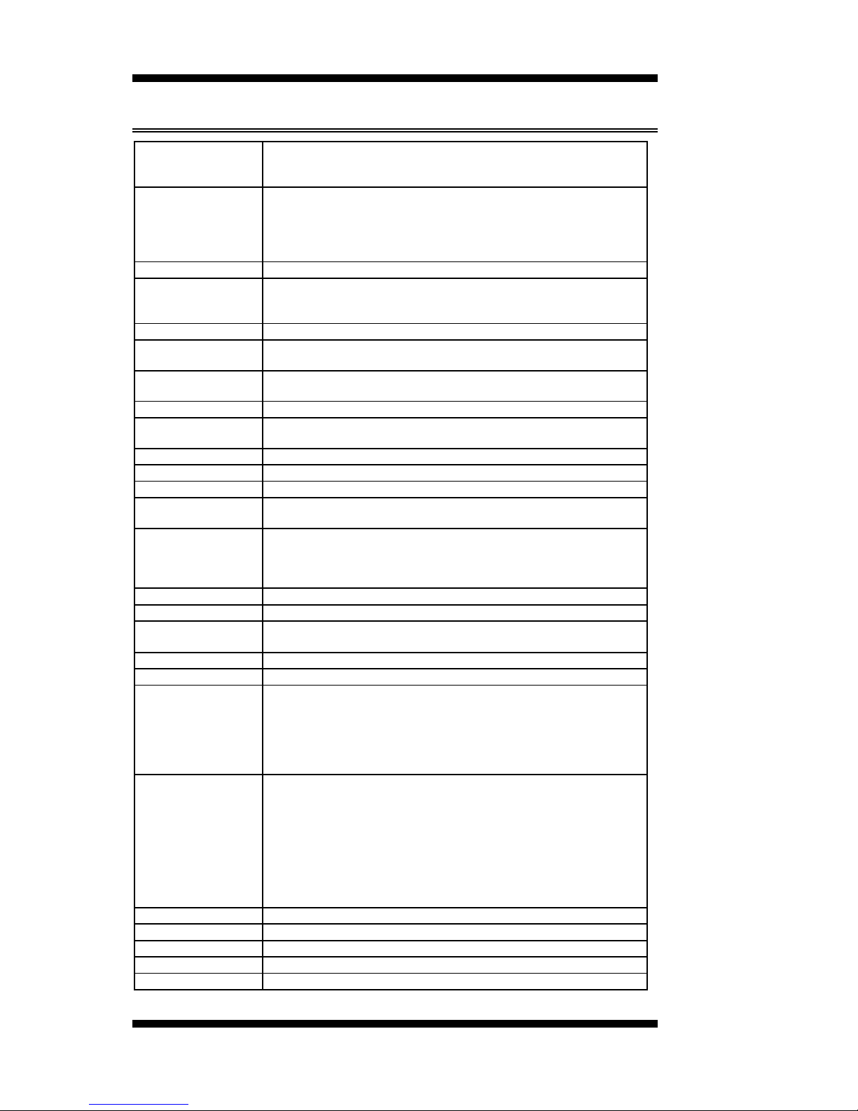
MI800 Specifications
CPU Type Intel New architecture CPU on 45nm processor
- Atom 230 (Diamondville Single Core)
- Atom 330 (Diamondville Dual Core)
CPU FSB CPU Clock speed = 1.60GHz
FSB=533MHz
L2 Cache=512K for SC / 1M for DC
Cores/Treads=1/2 threads.
TDP=4W for SC / 8W for DC
CPU Socket 473 pins micro-FCBGA on board
Chipset Intel 945GC Chipset
GMCH: 82945GC 34 mm x 34 mm -1202 balls FCBGA
ICH7: 82801GH: 31mm x 31mm -652-pin BGA
BIOS Award BIOS, support ACPI Function
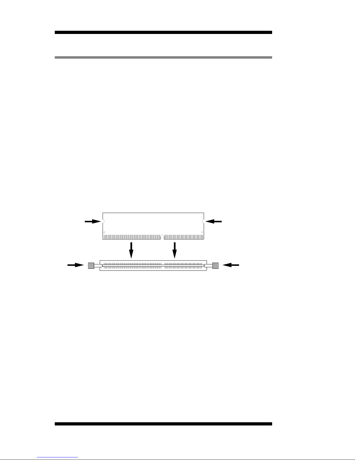
Memory DDRII 400/533 DIMM x 2 (w/o ECC function), supports Dual
channel. Max. 2GB
VGA The 82945GC GMCH provides an integrated graphics device
(IGD) delivering cost competitive 3D, 2D, and video capabilities.
DVI + LVDS Chrontel CH7307 + Chrontel CH7308C
LAN 1. ICH7 built-in 10/100BT MAC + Intel 82562ET PHY
2. Intel 82574L PCI Express Gigabit LAN controller x1
USB ICH7 built-in USB 2.0 host controller, support 6 ports
Serial ATA ICH7 built-in SATA controller, supports 2 ports
Parallel IDE ICH7 built-in one channel Ultra DMA 33/66/100, CF
Audio ICH7 built -in Audio controller ALC 662 5.1-Channel (Line-in,
Line-out & MIC)
LPC I/O Winbond W83627EHG: COM1 (RS232), COM2
(RS232/422/485),
Hardware monitor (3 thermal inputs, 4 voltage monitor inputs,
VID0-4 & 2 Fan Headers)
2’nd LPC I/O Fintek F81216DG COM3 & COM4 (RS232)
Digital IO 4 in & 4 out
Keyboard/Mouse
Connector Supports PS/2 Keyboard/Mouse
Expansion PCI slot x1, PCI-E (x1) slot x1 and Mini PCI-E (x1) socket x1
Power Connector DC Power jack x1 for +12V/+19V DC-in
Edge Connector PS/2 Connector x1 for keyboard/mouse
Gigabit LAN RJ-45 + dual USB stack connector
10/100 LAN RJ45 + dual USB stack connector
VGA+DVI-D stack connector
3x1 stack mini jacks (0.125”) for HD audio (Line-in, Line-Out, Mic)
DC-IN jack
On Board Header/
Connector 40 pins box-header x1 for IDE1
CF Connector x1 @ solder side
10 pins pin-headerx1 for Digital I/O
20 pins DF11 connectorx2 for COM1/COM2, COM3/COM4 (Pin 9
can be powered with 5V or 12V or as ring-in)
8 pins pin-header x 1 for USB 5,6
10 pins pin-header x1 for audio Line-Out & Mic
SATA connector x2 for 2 SATA ports
DF13 Connector x2 for LVDS
Watchdog Timer Yes (256 segments, 0, 1, 2…255 sec/min)
Other Modem Wakeup, LAN Wakeup
RoHS Yes
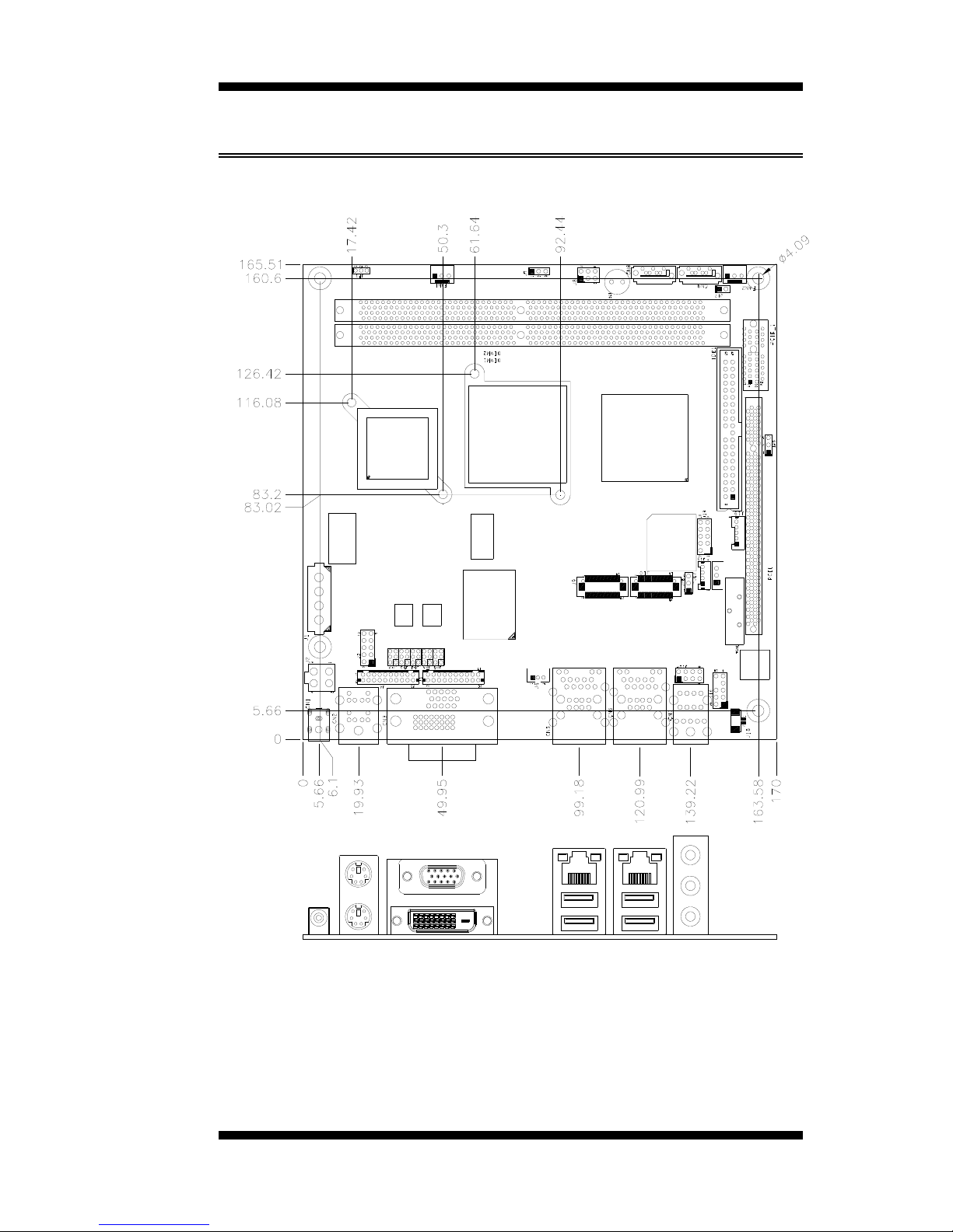
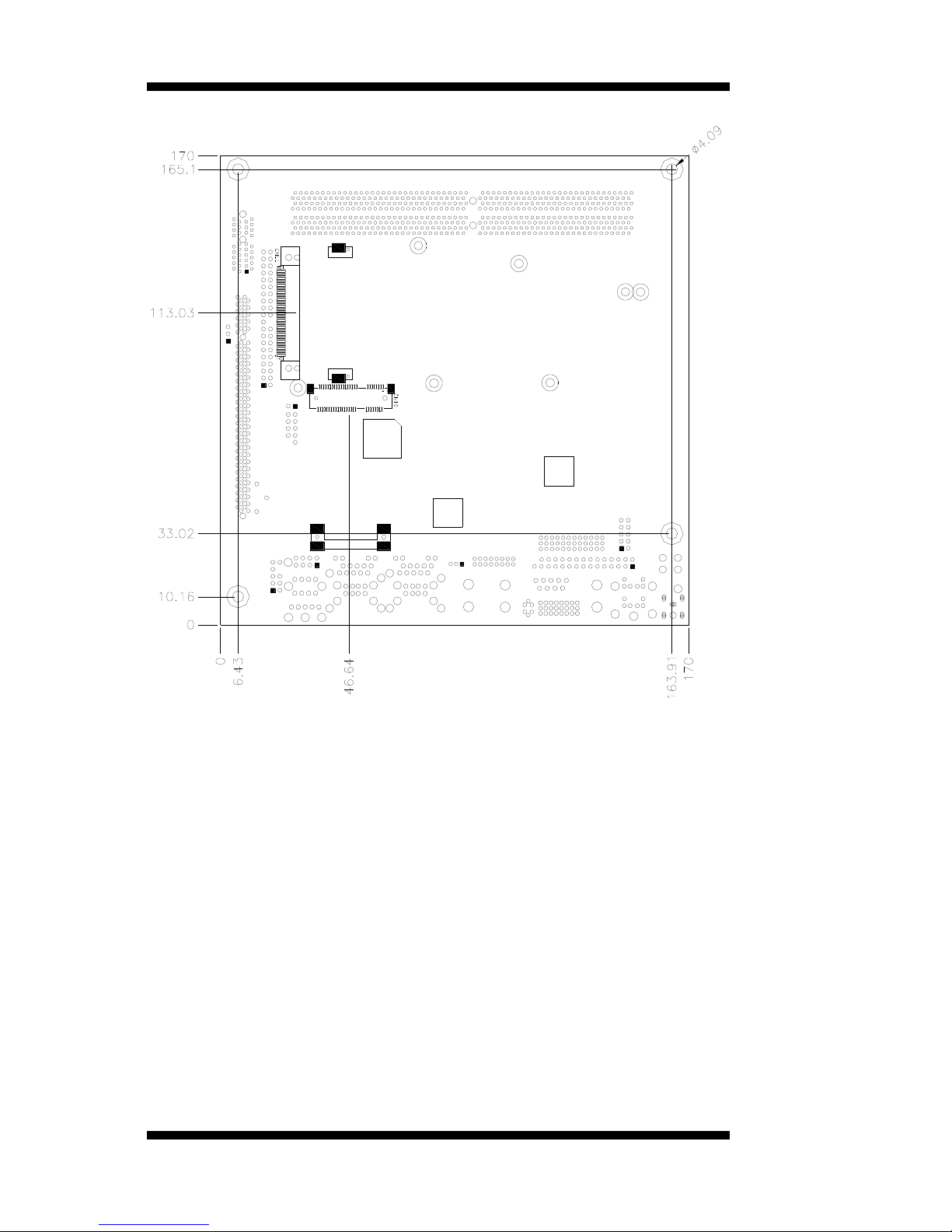
Form Factor4 Mini ITX
Board Size 170mm x 170mm