INTROD CTION
MI910 ser’s Manual 3
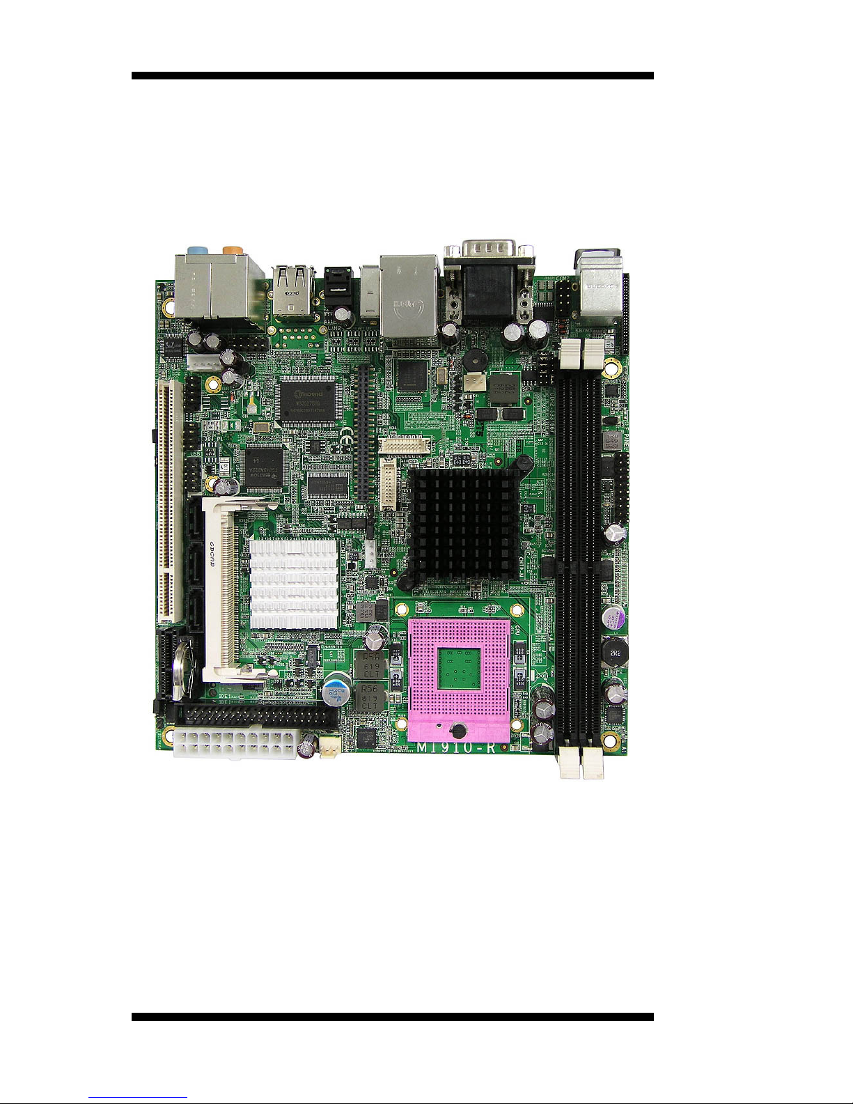
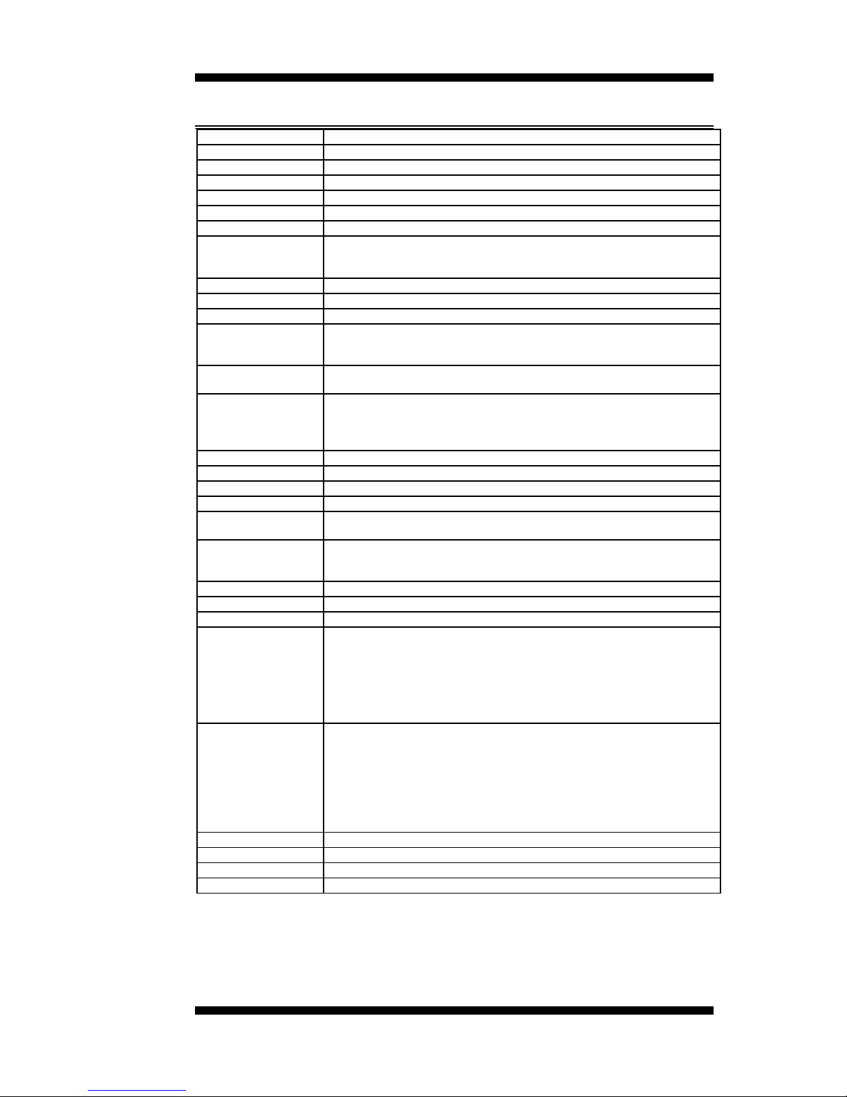
MI910 Specifications
CPU Supported Intel® Core
TM
2 Duo, Intel Celeron mobile
processors
CPU Voltage 0.700V ~ 1.5V (IMVP-6)
System Speed Up to 2.4GHz or above
CPU FSB 533MHz/800MHz FSB
Cache 1MB/2MB/4MB
Green /APM APM1.2
CPU Socket mPGA Socket 478
Chipset Intel GME965 Chipset
GMCH: GME965 1299-pin Micro-FCBGA
ICH8M: 82801HBM 678-pin mBGA
BIOS Award BIOS, support ACPI Function
Memory DDR2 667/533 SDRAM DIMM x2 (w/o ECC function), Max. 4GB
VGA GMA965 built-in, supports CRT
SDVO (Dual CH) Through ID390 card (Chrontel 7308, 24+24 bits single/dual channel
LVDS, Chrontel 7021, CRT)
Through ID391 card (Chrontel 7307C, DVI single or Dual)
LVDS LCD Panel GME965 built-in, supports 24+24 bits (Type 1 only), single or dual channel
LVDS
LAN 1. ICH8M 10/100/gigabit MAC + PHY (dual footprint option):
•Intel 82566DC Nineveh 10/100/1000 (MI910)
•Intel 82562V Ekron-N 10/100 (MI910L)
2. Marvell 88E8053 PCI-e Gigabit LAN controller x1 (MI910F)
USB ICH8M built-in USB 2.0 host controller, support 6 ports
Serial ATA Ports ICH8M built-in SATA controller, supports 2 ports
1394 TI TSB43LV22(dual port)
Parallel IDE ICH8M built-in one channel Ultra DMA 33/66/100,CF Type II
Audio ICH8M Built-in audio controller + AC97 Codec ALC885 w/ 7.1 channels,
SPDIF-OUT
LPC I/O W83627EHF: COM1, COM2 (RS232/RS422/RS485), slim FDC 1.44MB,
IrDA x1 & hardware monitor (3 thermal, 4 voltage monitor inputs, 2 fan
headers)
Digital IO 4 in & 4 out
Keyboard/Mouse Supports PS/2 Keyboard/Mouse Connector
Expansion Slots PCI slot x1, PIC-E (x1) slot x1 and Mini PCI socket x1
Edge Connector PS/2 connector x1 for keyboard/mouse
Gbit LAN RJ-45 + dual USB stack connector
10/100 LAN RJ45 + dual USB stack connector
DB9 x1 for COM 1; DB15 x1 for VGA
SPDIF-OUT connector x1; 1394 connector x1
RCA Jack 3x2 for Audio (Front-Out, Line-In, Mic, Center/LFE, Surround &
Surround Back)
Onboard Header/
Connector
40 pins box-header x1 for IDE1; 26 pins header x1 for slim floppy
CF Connector x1 @ solder side
10 pins pin-headerx1 for Digital I/O; 10 pins pin-header x1 for COM2
10 pins pin-header x 1 for USB 5,6; 5 pins pin-header x 1 for IrDA
DF13 connector x2 for LVDS;
10 pins pin-header x1 for audio Line-Out & Mic
4 pins pin-header x1 for CD in; 7 pins pin-header x1 for 1394
SATA connector x2 for SATA ports
Watchdog Timer Yes (256 segments, 0, 1, 2…255 sec/min)
System Voltage +5V, +3.3V, +12V, -12V, 5VSB (2A)
Others Modem Wakeup, LAN Wakeup
Board Size 170mm x 170mm (Mini ITX)
Note: MI910L uses GL960 chipset. It supports FSB 533MHz, DDR2
533MHz only.