Award MI930 User manual

MI930/MI930F
AMD Athlon™ 64 / Athlon™ 64 x2
(Dual Core) / Sempron™
Mini-ITX Motherboard
USER’S MANUAL
Version 1.0

Acknowledgments
Award is a registered trademark of Award Software International,
Inc.
PS/2 is a trademark of International Business Machines
Corporation.
AMD Athlon™ 64 / Athlon™ 64 x2 (dual core) / Sempron™
processors are registered trademarks of AMD Corporation.
Microsoft Windows is a registered trademark of Microsoft
Corporation.
Winbond is a registered trademark of Winbond Electronics
Corporation.
All other product names or trademarks are properties of their
respective owners.
ii MI930 User’s Manual

Table of Contents
Introduction.......................................................1
Product Description.............................................................1
Checklist..............................................................................2
MI930 Specifications ..........................................................3
Board Dimensions...............................................................4
Installations.......................................................5
Installing the CPU...............................................................6
Installing the Memory.........................................................7
Setting the Jumpers .............................................................8
Connectors on MI930........................................................12
BIOS Setup.......................................................23
Drivers Installation......................................41
SM Bus Controller Driver Installation..............................42
VGA Drivers Installation ..................................................45
Realtek Codec Audio Driver Installation..........................47
LAN Drivers Installation...................................................50
Appendix...........................................................51
A. I/O Port Address Map...................................................51
B. Interrupt Request Lines (IRQ)......................................52
C. Watchdog Timer Configuration....................................53
MI930 User’s Manual iii

iv MI930 User’s Manual
This page is intentionally left blank.

INTRODUCTION
MI930 User’s Manual 1
Introduction
Product Description
The MI930 Mini ITX board incorporates the Mobile AMD M690T Express
Chipset for Embedded Computing, consisting of the AMD M690T (North
Bridge) and SB600 (South Bridge), an optimized integrated graphics solution
with an 800MHz front-side bus. Dimensions of the board are 170mm x 170mm.
The M690T integrates an ATi Radeon X700-based graphics engine supporting
dual display, an LVDS interface, an integrated TMDS controller, and operates at
core speeds of up to 400 MHz. MI930 features a low-power design, is validated
with the AMD Athlon™ 64 / Athlon™ 64 x2 (dual core) / Sempron™ on 65nm
process. With two dual channel DDR2 800MHz DIMM sockets on board, the
board supports up to 4GB of DDR2 system memory.
The main features of the board are:
Supports AMD Athlon™ 64 / Athlon™ 64 x2 (dual core) / Sempron™
Supports up to 2.8GHz, 800MHz FSB
Two DDR2 SDRAM DIMM, Max. 4GB memory
2x Marvell PCI-Express Gigabit LAN
AMD M690T Express VGA for CRT / LVDS / DVI
2x SATA, 6x USB 2.0, 2x COM, Watchdog timer
1x PCI slot (expansion to two PCI slots)

INTRODUCTION
2MI930 User’s Manual
Checklist
Your MI930 package should include the items listed below.
•The MI930 Mini-ITX motherboard
•This User’s Manual
•1 CD containing chipset drivers and flash memory utility
•Cable kit (IDE, Serial port, Serial ATA)

INTRODUCTION
MI930 User’s Manual 3
MI930 Specifications
CPU Supported AMD Athlon™ 64 / Athlon™ 64 x2 (dual core) / Sempron™ 64-bit
processor integrated w/ DDRII memory controller in CPU.
CPU Voltage 0.700V ~ 1.5V
System Speed Up to 2.8GHz or above
CPU FSB 800MHz FSB
Cache 128K/256K/512K1MB/2MB
Green /APM APM1.2
CPU Socket Socket AM2 (940pin)
Chipset ATI M690T / SB600 chipset
NB: M690T, 465-ball FCBGA (21x21mm)
SB: ATi SB600, 549-ball FCBGA (23x23mm, 0.8mm pitch)
BIOS Award BIOS, support ACPI Function
Memory DDR2 800/667/533 SDRAM DIMM x2 (w/o ECC function), Max. 4GB
VGA ATi M690T built-in Radeon X700 based graphic engine, supports full
DirectX9.0. RS690T integrates TMDS controller for DVI and 18 or
24-bit LVDS interface. Supports dual display for below display
combinations:
- Analog (CRT) + digital (DVI or LVDS)
- Both digital (DVI + LVDS)
LAN Marvell 88E8053 PCI-e Gigabit LAN controller x2
USB ATi SB600 built-in USB 2.0 host controller, support 6 ports
Serial ATA Ports ATi SB600 built-in SATA II (3.0Gb/sec) host controller, supports 2
ports and RAID 0, 1 function
Parallel IDE ATi SB600 built-in one channel Ultra DMA 33/66/100/133
Audio ATi SB600 built-in audio controller + AC97 Codec ALC888 w/ 7.1
channels
LPC I/O W83627EHG: COM1 (RS232), COM2 (RS232/422/485) & hardware
monitor (3 thermal inputs, 4 voltage monitor inputs, 2 fan headers).
Parallel, IrDA & Floppy not used
Digital IO 4 in & 4 out
Keyboard/Mouse Supports PS/2 keyboard/mouse connector
Expansion Slots PCI slot (32bits/33MHz) x1
8x2 pin-header x1 for LPC TPM adaptor card (reserved) or
8x2 pin-header x1 for LPC 2nd I/O adaptor card COM3 /COM4
(RS232) or COM3 /COM4 /COM5 /COM6 (RS232) (reserved)
Edge Connector PS/2 connector x1 for keyboard/mouse
DB9 & DVI stack connector x1 for COM 1 and DVI
RJ-45 + dual USB stack connector x2 for LAN1, 2 & USB1~4
RCA jack 3x1 for audio (Line-in, Line-Out, Mic.) & pin header for front
panel (Line-Out2, Mic2)
Onboard Header/
Connector DF13-20 x2 for LVDS
40-pin, 2.54mm, box-header x 1 for IDE1
5x2 pin-header x1 for USB5~6
5x2 pin-header x1 for front audio (headphone & Mic.)
10 pin-header x1 for COM2
8x2 pin-header x1 for VGA
Watchdog Timer Yes (256 segments, 0, 1, 2…255 sec/min)
System Voltage +5V, +3.3V, +12V, -12V, 5VSB (2A)
Others Modem Wakeup, LAN Wakeup
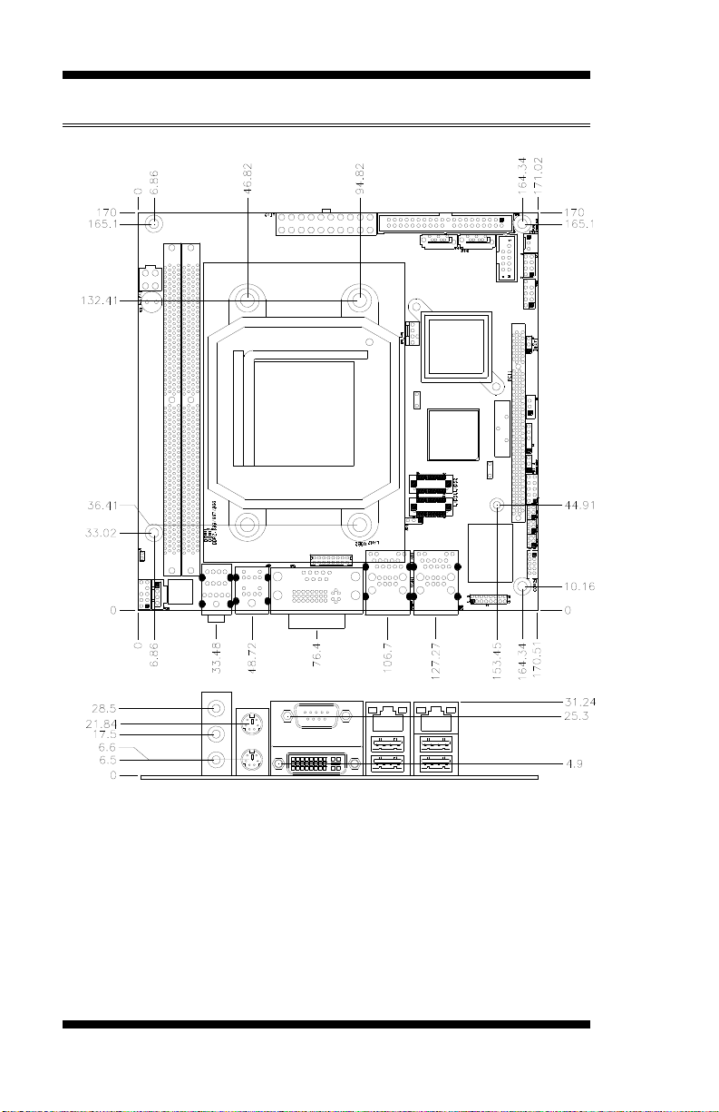
Board Size 170mm x 170mm (Mini ITX)

INTRODUCTION
[
Board Dimensions
4MI930 User’s Manual

INSTALLATIONS
MI930 User’s Manual 5
Installations
This section provides information on how to use the jumpers and
connectors on the MI930 in order to set up a workable system. The
topics covered are:
Installing the CPU........................................................................ 6
Installing the Memory.................................................................. 7
Setting the Jumpers...................................................................... 8
Connectors on MI930 ................................................................ 12

INSTALLATIONS
Installing the CPU
The MI930 board supports a Socket AM2 (940-pin) processor socket for
AMD Athlon™ 64 / Athlon™ 64 x2 (dual core) / Sempron™processors.
To install the CPU, unlock first the socket by pressing the lever
sideways, then lift it up to a 90 degree angle as shown below. Then,
position the CPU above the socket such that the CPU corner aligns with
the gold triangle matching the socket corner with a small triangle.
Carefully insert the CPU into the socket and push down the lever to
secure the CPU. Then, install the heatsink and fan.
NOTE: Ensure that the CPU heat sink and the CPU top surface are in
total contact to avoid CPU overheating problem that would
cause your system to hang or be unstable.
6MI930 User’s Manual

INSTALLATIONS
Installing the Memory
The MI930 board supports two DDR2 memory socket for a maximum
total memory of 4GB in DDR2 memory type.
Installing and Removing Memory Modules
To install the DDR2 modules, locate the memory slot on the board and
perform the following steps:
1. Hold the DDR2 module so that the key of the DDR2 module aligned
with that on the memory slot.
2. Gently push the DDR2 module in an upright position until the clips of
the slot close to hold the DDR2 module in place when the DDR2
module touches the bottom of the slot.
3. To remove the DDR2 module, press the clips with both hands.
DDR2 Module
Lock Lock
Lock Lock
MI930 User’s Manual 7

INSTALLATIONS
8MI930 User’s Manual
Setting the Jumpers
Jumpers are used on MI930 to select various settings and features
according to your needs and applications. Contact your supplier if you
have doubts about the best configuration for your needs. The following
lists the connectors on MI930 and their respective functions.
Jumper Locations on MI930...........................................................9
JBAT1: Clear CMOS Setting .......................................................10
JP1: LCD Panel Power Selection..................................................10
JP2: PCI Riser Card Selection......................................................10
JP3, JP4, JP5: RS232/422/485 (COM2) Selection.......................11

INSTALLATIONS
Jumper Locations on MI930
Jumpers on MI930............................................................................Page
JP1: LCD Panel Power Selection ................................................. 10
JP2: PCI Riser Card Selection...................................................... 10
JBAT1: Clear CMOS Setting....................................................... 11
MI930 User’s Manual 9

INSTALLATIONS
JBAT1: Clear CMOS Setting
JBAT1 Setting
Normal
Clear CMOS
JP1: LCD Panel Power Selection
JP1 LCD Panel Power
3.3V
5V
JP2: PCI Riser Card Selection
JP2 Riser Card
IP390 Riser Card
Install
IP151, IP240 Riser Card
Install
10 MI930 User’s Manual

INSTALLATIONS
JP3, JP4, JP5: RS232/422/485 (COM2) Selection
COM1 is fixed for RS-232 use only.
COM2 is selectable for RS232, RS-422 and RS-485.
The following table describes the jumper settings for COM2 selection.
COM2
Function RS-232 RS-422 RS-485
Jumper
Setting
(pin closed)
JP5:
1-2
JP4:
3-5 & 4-6
JP3:
3-5 & 4-6
JP5:
3-4
JP4:
1-3 & 2-4
JP3:
1-3 & 2-4
JP5:
5-6
JP4:
1-3 & 2-4
JP3:
1-3 & 2-4
COM2 is jumper selectable for RS-232, RS-422 and RS-485.
Pin # Signal Name
RS-232 R2-422 RS-485
1 DCD TX- DATA-
2 RX TX+ DATA+
3 TX RX+ NC
4 DTR RX- NC
5 Ground Ground Ground
6 DSR RTS- NC
7 RTS RTS+ NC
8 CTS CTS+ NC
9 RI CTS- NC
10 NC NC NC
MI930 User’s Manual 11

INSTALLATIONS
12 MI930 User’s Manual
Connectors on MI930
Connector Locations on MI930...........................................................13
CN1: Audio Connector........................................................................14
CN2: PS/2 Keyboard and PS/2 Mouse Connectors.............................14
CN3: COM1 and DVI-I Connector .....................................................14
CN4, CN5: GbE RJ45 (MI930) and USB1/2 Ports .............................15
CN6, CN7: GbE RJ-45 (MI930F) and USB3/4 Ports..........................15
ATX1: ATX 12V Power Connector....................................................15
ATX2: ATX Power Supply Connector................................................16
FAN1: System Fan Power Connector..................................................16
FAN2: CPU Fan Power Connector......................................................16
F_USB1: USB0/USB1 Connector.......................................................16
IDE1: IDE Connector ..........................................................................17
SATA1, SATA2: SATA Connectors...................................................17
COM2: COM2 Serial Port...................................................................17
LVDS1, LVDS2: LVDS Connectors (1st channel, 2nd channel)........18
J3: CD-In Pin Header...........................................................................18
J4: For LPC I/F Adaptor Card .............................................................18
ID394 with Fintek F81216, 2 or 4 Serial Ports....................................18
ID395 Winbond WPCT200 x1 for TPM1.2 ........................................18
J5: SPI Flash Connector (factory use only) .........................................18
J6: Power LED Connector...................................................................18
J7 (F_PANEL): System Function Connector ......................................19
J8: LCD Backlight Connector..............................................................19
J9: Digital I/O ......................................................................................20
PCI1: PCI Slot (supports 2 Master).....................................................20
ID395 WINBOND WPCT200 for TPM1.2.........................................20
ID394 LPC Serial Ports Adaptor Card ................................................21

INSTALLATIONS
Connector Locations on MI930
CN1: Audio Connector............................................................................................................14
CN2: PS/2 Keyboard and PS/2 Mouse Connectors.................................................................14
CN3: COM1 and DVI-I Connector.........................................................................................14
CN4, CN5: GbE RJ45 (MI930) and USB1/2 Ports.................................................................15
CN6, CN7: GbE RJ-45 (MI930F) and USB3/4 Ports .............................................................15
ATX1: ATX 12V Power Connector........................................................................................15
ATX2: ATX Power Supply Connector ...................................................................................16
FAN1: System Fan Power Connector .....................................................................................16
FAN2: CPU Fan Power Connector .........................................................................................16
F_USB1: USB0/USB1 Connector...........................................................................................16
IDE1: IDE Connector..............................................................................................................17
SATA1, SATA2: SATA Connectors ......................................................................................17
COM2: COM2 Serial Port.......................................................................................................17
LVDS1, LVDS2: LVDS Connectors (1st channel, 2nd channel)...........................................18
J3: CD-In Pin Header ..............................................................................................................18
J4: For LPC I/F Adaptor Card.................................................................................................18
ID394 with Fintek F81216, 2 or 4 Serial Ports .......................................................................18
ID395 Winbond WPCT200 x1 for TPM1.2............................................................................18
J5: SPI Flash Connector (factory use only).............................................................................18
J6: Power LED Connector.......................................................................................................18
J7 (F_PANEL): System Function Connector..........................................................................19
J8: LCD Backlight Connector.................................................................................................19
J9: Digital I/O..........................................................................................................................20
MI930 User’s Manual 13

INSTALLATIONS
CN1: Audio Connector
CN2: PS/2 Keyboard and PS/2 Mouse Connectors
PS/2 Mouse
PS/2 Keyboard
Signal Name Keyboard Mouse Signal Name
Keyboard data 1 1 Mouse data
N.C. 2 2 N.C.
GND 3 3 GND
5V 4 4 5V
Keyboard clock 5 5 Mouse clock
N.C. 6 6 N.C.
CN3: COM1 and DVI-I Connector
[
Signal Name Pin # Pin # Signal Name
DCD 1 6 DSR
RXD 2 7 RTS
TXD 3 8 CTS
DTR 4 9 RI
GND 5 10 Not Used
14 MI930 User’s Manual

INSTALLATIONS
Signal Name Pin # Pin # Signal Name
DATA 2- 1 16 HOT POWER
DATA 2+ 2 17 DATA 0-
Shield 2/4 3 18 DATA 0+
DATA 4- 4 19 SHIELD 0/5
DATA 4+ 5 20 DATA 5-
DDC CLOCK 6 21 DATA 5+
DDC DATA 7 22 SHIELD CLK
VSYNC 8 23 CLOCK -
DATA 1- 9 24 CLOCK +
DATA 1+ 10 C1 N.C.
SHIELD 1/3 11 C2 N.C.
DATA 3- 12 C3 N.C.
DATA 3+ 13 C4 N.C.
DDC POWER 14 C5 N.C.
A GROUND 1 15 C6 N.C.
CN4, CN5: GbE RJ45 (MI930) and USB1/2 Ports
CN6, CN7: GbE RJ-45 (MI930F) and USB3/4 Ports
ATX1: ATX 12V Power Connector
This connector supplies the CPU operation voltage
Pin # Signal Name
1 Ground
2 Ground
3 +12V
4 +12V
MI930 User’s Manual 15

INSTALLATIONS
ATX2: ATX Power Supply Connector
11 1
20 10
Signal Name Pin # Pin # Signal Name
3.3V 11 1 3.3V
-12V 12 2 3.3V
Ground 13 3 Ground
PS-ON 14 4 +5V
Ground 15 5 Ground
Ground 16 6 +5V
Ground 17 7 Ground
-5V 18 8 Power good
+5V 19 9 5VSB
+5V 20 10 +12V
FAN1: System Fan Power Connector
FAN1 is a 3-pin header for system fans. The fan must be a 12V
(500mA).
Pin # Signal Name
1 Ground
2 +12V
3 Rotation detection
FAN2: CPU Fan Power Connector
FAN2 is a 4-pin header for the CPU fan. The fan must be a 12V fan.
Pin # Signal Name
4 Control
3 Sense
2 +12V
1 Ground
F_USB1: USB0/USB1 Connector
Signal Name Pin Pin Signal Name
Vcc 1 2 Vcc
D0- 3 4 D1-
D0+ 5 6 D1+
Ground 7 8 Ground
NC 9 10 Ground
Note: This USB connector is compatible with USB 2.0 devices only.
16 MI930 User’s Manual
This manual suits for next models
1
Table of contents
Other Award Motherboard manuals