Axesstel TX240G User manual

Control Number
:
42660
Item Number
:
114
Addendum StartPage
:
0


.a
^
SOAH DOCKET NO. 473-15-3697
DOCKET NO. 42660
^$ ^^ 4: J^
PUBt 1C tTi
IL
r ^
1 T YC^ttM1SS
APPLICATION OF GS TEXAS
§
BEFORE THE STATE OfiI+'1^jLERtI
VENTURES, LLC FOR DESIGNATION
§
AS AN ELIGIBLE
§
TELECOMMUNICATIONS CARRIER
§
OF
("ETC") AND AS AN ELIGIBLE
§
TELECOMMUNICATIONS PROVIDER §
("ETP")
§
ADMINISTRATIVE HEARINGS
GS TEXAS VENTURES, LLC MOTION FOR LEAVE TO LATE-FILE EXHIBITS
TO THE HONORABLE ADMINISTRATIVE LAW JUDGE:
COMES NOW,
G.S. Texas Ventures,
LLC ("GSTV")
and files this, its Motion for Leave
to Late-File Exhibits, pursuant and PUC PROC. R. 22.226(d). In accordance with SOAH Order
No. 8, GSTV has reviewed every GSTV and Staff exhibit that was admitted under seal at the
hearing and determined that several can be declassified in whole or in part. GSTV has informed
Staff of the declassification decisions applicable to Staff,s trial exhibits, and GSTV understands
that Staff will make its own filing implementing those declassifications. The late-filed exhibits
attached hereto are the GSTV trial exhibits that GSTV has determined can be declassified. Each
relates to the exhibits filed under seal with the Rebuttal Testimony of Michael Hatfield admitted
into evidence as GSTV trial exhibit 2. Each late-fled exhibit is described as follows:
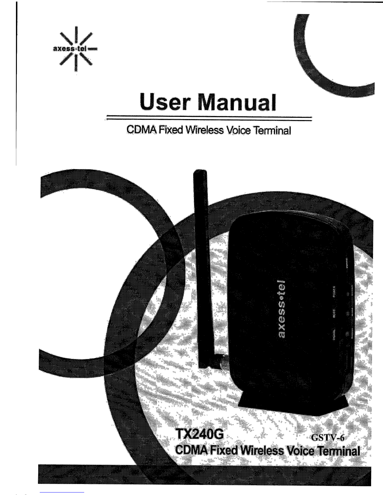
GSTV-6 Confidential
Exhibit
C to
Rebuttal
Testimony of Michael
Hatfield
(
declassified
in whole).
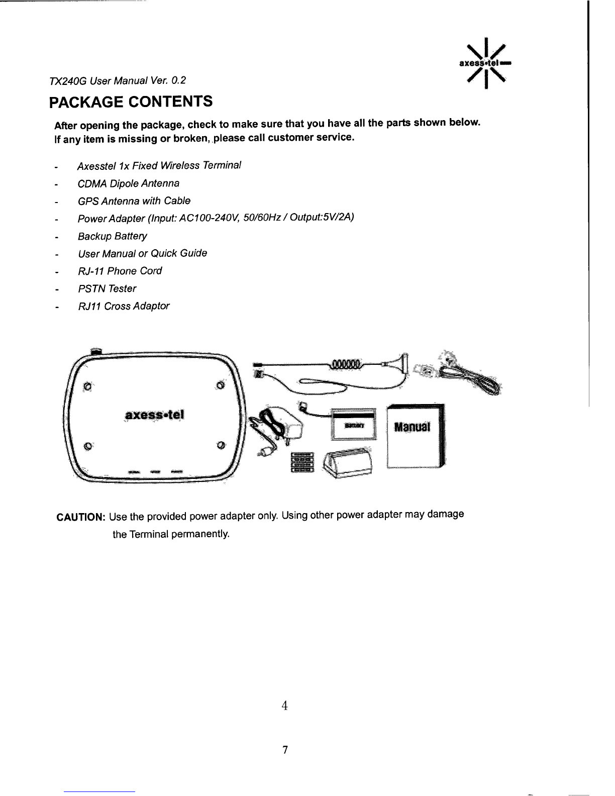
User manuals to potential wireless receivers.
GSTV-7
ConfidentialExhibit
D to Rebuttal Testimony of Michael Hatfield
(declassified in part).
FCC "fixed wireless" labels
and user manual
description of device as "fixed wireless" have been declassified.
The
remaining non-public information is omitted from this exhibit.
GSTV-8 Confidential
Exhibit
E to Rebuttal Testimony of Michael Hatfield
(declassified
in
part).
Communications
with
Verizon regarding
establishing unbundled network elements ("UNEs") pursuant the GSTV-
Verizon interconnection agreement have been declassified. The remaining
non-public information is omitted from this exhibit.
114

GSTV-9
Confidential Exhibit F to Rebuttal Testimony of Michael Hatfield
(declassified in part).
Wire center map of GSTV switch, switch network
diagram have been declassified, and the switch order form has been
redacted in part.
The remaining non-public information is omitted from
this exhibit.
GSTV-10 Confidential
Exhibit I to Rebuttal Testimony of Michael Hatfield
(declassified in part).
Some of the communications between GSTV and
Sprint have been declassified in whole or in part. The remaining non-
public information is omitted from this exhibit.
Respectfully submitted,
/s/MatthewA. Henry
Matthew A. Henry
MCCOLLOUGHIHENRY, PC
1250 S. Capital of Texas Highway
Building 2-235
West Lake Hills, TX 78746
Phone: (512) 888-1114
Fax: (512) 692-2522
Dated: January 25, 2016
Counsel
for G
S.
Texas Ventures, LLC
CERTIFICATE OF SERVICE
I,
Matthew A. Henry, counsel for G.S. Texas Ventures, LLC,
certify that a copy of this
document was served on all parties of record in this proceeding on January 25, 2016 in the
following manner: hand delivery.
/s/Matthew A. Henry
Matthew A. Henry
Counsel
for G.S. Texas Ventures, LLC
2

GSTV TRIAL EXHIBIT 6 (LATE-FILED)
USER MANUALS TO POTENTIAL WIRELESS RECEIVERS
(DECLASSIFIED IN WHOLE)

^
y j;^S -^
User Manual
COMA Fixed Wireless Voice Terminal

exess•tel
TX240G User Manual Ver. 0. 2
INTRODUCTION
OVERVIEW
TX240G is a Fixed Wireless Terminal designed to provide better wireless connectivity between wired
landline telephone (POTS) and CDMA 800/1900 dual bands network with high sensitivity to receive
signal and large transmitting power to expand extensively the effective coverage of CDMA service.
Global Positioning System (A-GPS) feature provides E911 service with accurately determining the
location of caller.
FEATURES
-
CDMA2000 1x (backward compatible to IS-95 A/B) 800/1900 MHz Dual Bands
-
A-GPS for E911 (SMA Antenna Connector)
-
TTY/TDD
Telephone Support
-
3 multi-colored LED Indicators
(
Signal, Mode, Voice Mail Waiting and Power)
-
2 R-J11 Ports
(
with max. 5 REN)
-
Dial-Tone and DTMF Generation
-
Desktop and Wall-Mountable
-
Call
Waiting, Three-way Calling and Call Forwarding
-
Call Restriction
-
Type II Caller ID (or Call Waiting ID)
-
OTA(IS-683A)
2
5

\f^
axess•t^l.«.
/1\
TX240G User Manual STD Ver. 0.2
SAFETY PRECAUTIONS
1.
Avoid placing the terminal in a dusty location, or near a source of gas or fire.
2. Don not shake, hit or drop the terminal.
3. To clean the outside of the terminal, use only a soft, dry cloth. The chemicals in alcohol, benzene or
Acetone can damage the surface of the terminal.
4. Do not twist or pull the cables.
5. Do not disassemble the terminal.
6. Do not use the power adapter if:
- The power cord is damaged.
- The adapter
has been damaged
in any way.
7. Use only the
AXESSTEL
provided adapter. Do not use
the AXESSTEL
adapter for any other
Purposes.
8. Use only the AXESSTEL provided antenna. Do not use the antenna for any other purposes..
9. Frequency and length of use can affect the life of the self-charging battery. Contact your customer
service if the battery is not operating properly.
10. Use only the designated self-charging battery. Dispose of exhausted batteries properly.
Never discard a battery in or near fire or flame.
11. Do not use the terminal near water, for example, near a bathtub, sink, wet basement, or swimming
pool.
NOTE: The input voltage and the shape of the plug may
vary from country to country.
3
6

TX240G User Manual Ver. 0.2
PACKAGE CONTENTS
axess•tel••^
/1`
After
opening the package, check to make sure that you have all the parts shown below.
If any item is missing or broken, please call customer service.
-
Axesstel 1x Fixed Wireless Terminal
-
CDMA Dipole Antenna
-
GPS Antenna with
Cable
-
PowerAdapter (Input: AC100-240V, 50/60Hz / Output:5V/2A)
-
Backup Battery
-
User
Manual or
Quick
Guide
-
RJ-11 Phone Cord
-
PSTN Tester
-
RJ11
Cross
Adaptor
ax@ss#tE.'l
a
^ rar
Manual
f
..
^ ^ -
.....
.
lY"
^
.. y..
CAUTION: Use the provided power adapter only. Using other power adapter may damage
the Terminal permanently.
4
7

`r I
axess•te1am
/1\
TX240G
User
Manual STD Ver. 0.2
BASIC INSTALLATION
INTERNAL BATTERY INSTALLATION
This TX210G
operates by receiving electricity from an electrical outlet or internal battery.
1.
Open battery cover on the bottom side of the terminal.
2. Connect the Battery power cable to terminal.
3. Insert the battery pack in the right position between the hold bars.
4. Close the battery cover.
a OoQ^^QQOOO ni
Q;UQL^C100JGb''
JO00^
°n^^" dI^Sl,/
..
.......
.........
^^y r
Battery
C^
c^Qiooo
6 00 oco z
U4bQCPU^U6L70QGU.^
4'^t ^ _.._
..
...
.
..
. ^'
_
Setting up the Terminal
1.
Connect the antenna by screwing into the TNC connector of the back of the terminal.
2. Connect an
analog
phone or cordless telephone to the terminal using an RJ-1 1 cord.
NOTE:
Use the wire landline telephone compatible to FCC part 68 only. Non-compliant phones may
not work properly.
,
,.
5
8

TX240G
User
Manual Ver. 0. 2
3. Plug the AC adapter jack into the DC 5V jack of the Terminal.
4. Plug the AC adapter plug into an appropriate electrical outlet.
Connecting the terminal to home phone wall outlet.
\1i
axess•tet•w
I 1\'
5. TX240 can
be connected to the home wall phone jack to allow users to use phones
from
any home
wall jack if the home wall phone jacks
do not
have existing service and are not powered.
Before
connecting the terminal to home wall jack, please make sure that the home wall jacks are not live and
do not have any power.
To test, please see the next section, "Wall Jack Tester".
WALL JACK
TESTER (PSTN Tester)
Optional wall jack tester check if the wall phone jack is powered by existing or previous landline phone
service.
IMPORTANT NOTE
DO NOT CONNECT
YOUR TERMINAL TO WALL JACK
IF PSTN
LINE IS STILL
IN SERVICE.
Connecting the terminal to the live wall jack may interfere with the existing phone service and/or
damage the terminal.
1.
Plug the tester into the wall jack.
2. If tester's Green colored LED turns on, PSTN line is still live and powered. In this case contact
you rexisting or previous landline phone service provider to disconnect the power.
Alternately, 2-line
cross adapter may be used to bypass the powered first phone line (pin 2 and 3) if the second line (pin
1
and 4) is not powered.
3. If Green colored LED does not turn on, wall phone jack is not powered and you can safely connect
your terminal to wall jack.
6
9

*NJ/
axess•tel.•.
/1\
TX240G User Manual STD Ver. 0.2
WALL MOUNT INSTALLATION
1.
Mark two mounting holes' locations to match the screw hole in the back of the terminal.
2. Drill two holes at the marked locations.
3. Tighten the screws until the head is about 5mm from the wall.
4. Plug in the power connector and route the cord in the groove, if needed.
5. Screw the antenna into antenna connector.
6. Hang the terminal on the screw using the two holes in the back.
7. Push the terminal down until the unit is firmly locked into place.
tJ
C
;1[.JJ^
.
Fr1^i
N
^^'
^ Jp [t ^ll
0
^'
i}
`JQpf7OQOC
7040^i '""^.
onarscaaot ^
^oc^^ ( ^7?
A-GPS for E911
Your
terminal supports
AGPS feature
to
meet U.S.
FCC 911 mandate
making the location of a
terminal available for callers in emergency situations. During the emergency call, all the LEDs on the
terminal blink and your location can determined by the service provider.. In order to increase the
location accuracy, the external GPS antenna must be connected to and positioned at a location that
can receive satellite signals, such as outside the building or near the windows.
7
10

TX240G User
Manual Ver. 0. 2
1.
Connect the antenna to the GPS SMA connector on the terminal.
\I/
at
/1\
2. Place the Magnetic Pad at a location that has no obstruction to the sky, such as outdoor or windows.
3. Put the A-GPS antenna on the magnetic pad and position the antenna to face outside.
Note: Any obstruction to sky will degrade the GPS signal and degrade location accuracy.
t
4?....i
^ :.
8
11

TERMINAL
Item
Color
Status
Description
Power
In Battery Mode: Fully Charged
Solid
Green
In Adaptor mode: Connected
Blinking
Charging
Solid
Mid Battery Level
Orange
Blinking
Battery Error
"
^
Solid
Low Battery
^
ed
Blinking
Low Battery Warning
Off
-
No Battery
Green
Solid
Excellent Signal
Signal
Orange
Solid
Good Signal
Solid
Low Signal
Blinking
Limited Service
OFF
-
No service
Solid
Off-Hook or In Use
Gree
n
Blinking
Incoming Call
Mode
Solid
-
Orange
Blinking
Voice Mail Waiting
Solid
-
Re^f .
Blinking
-
E911 Call
ll,
All LEDs
Blinking
-All LEDs blink during emergency call
12

TX240G User
Manual Ver. 0. 2
B
as
i
c O
p
eration
POWER ON/OFF
MAKING CALLS
RECEIVING CALLS
10
axsss•tet ^•
/1\
13

\ I ^
axess•tel.••R
/1\
POWER ON / OFF
Power switch is located on the back side of the terminal
1. Turn on the unit by moving switch to ON position.
2. Turn off the unit by moving switch to OFF position.
TX240G
User
Manual STD
Ver. 0.2
NOTE: When you turn on the terminal, it automatically searches for service signal.
After successfully acquiring service signal, the Signal LED turns to Green, Orange or
Red depending on signal strength.
MAKING CALLS
1.
Check if the terminal is turned on.
2. Pick up the handset of the phone.
3. If you hear the dial tone, dial the desired telephone number by, using the analog phone or cordless
phone keypad.
Note : Dial number of maximum 32 digits, including * and #, can be entered.
4.
Wait for about 3 seconds until the call is automatically made by the terminal.
(
Auto dial time can
be configured from 3 seconds to 9 seconds, or off)
Note: Press <#> button to make call right away after entering the dial number.
5.
When the other recipient answers, begin conversation.
Note: If Connection Alert is turned on, a beep is heard when the call is connected.
6. To hang up, put the phone receiver back on the phone
or press TALK or OFF
button on your phone.
RECEIVING CALLS
The analog phone or cordless telephone(s) connected to the terminal ring when an incoming
call come in.
1.
Pick up the telephone receiver to answer the call.
2. To disconnect after finished, replace the handset on the phone.
Note: If using cordless phone, press TALK or ON button to answer the phone call.
Refer to analog
11
14

\I/
^t
TX240G
User
Manual Ver. 0. 2
phone or cordless phone user manual for instruction.
Note
1:
Make sure that the attached telephone's ringer is enabled.
Note 2:
When there is an incoming call when you are already holding the receiver, press any
key on the numeric keypad to answer the call.
12
15

^
ax` •te
'N
TX240G
User
Manual STD
Ver. 0.2
Advanced Features
Sound
Adjusting Voice Volume
Adjusting
Alert Volume
Setting One Minute Alert
Setting Voice
Privacy Alert
Setting Connection Alert
General
Setting Caller ID
Setting Auto Send Time
Setting DTMF Length
Security
Changing Lock Code
Restricting Ongoing Calls
Factory Reset
TTY/TDD
Mode Setting
13
16

\li
axsss•iet••wR
TX240G User Manual Ver. 0. 2
ADJUSTING VOICE VOLUME
You can control the volume level of the terminal
1.
Pick up the handset and check the dial-tone.
2. Press <*><*><1><1><*> to raise the voice volume
3. Press <*><*><1><1><#> to lower the voice volume
4. A confirmation beep will sound for 3 seconds
Notel:
Some telephones may have their own volume control. Use both the terminal and the
telephone volume controls to optimize the sound level.
Note2:
Volume can not be adjusted while conversation is in progress.
ADJUSTING ALERT TONE VOLUME
1.
Pick up the handset.
2. Press <*><*><1><2><*> to raise the alert tone volume.
3. Press <*><*><1><2><*> to lower the alert tone volume.
SETTING ONE MINUTE ALERT
When this feature is enabled, a discrete tone is generated at each one minute interval
on the receiver during conversation for both incoming and outgoing calls. This tone is
to help the user keep track of the phone usage.
To change the setting,
1.
Pick up the handset.
2. Press <*><*><1><3><#>
to enable the feature.
3. Press <*><*><1><3><*>
to disable the feature..
SETTING VOICE PRIVACY ALERT
If enabled,
beep
is generated
when Voice Privacy is on.
To change
the setting:
1.
Pick
up the handset.
2. Press <*><*><1><4><#>
to enable the feature.
3. Press <*><*><1><4><*>
to disable the feature..
SETTING CONNECTION ALERT
14
17

\1/
axess•tel•.•
/1\
TX240G
User
Manual STD
Ver. 0.2
If enabled, a discrete tone is generated on the receiver when the call is connected.
To change the setting:
1. Pick up the handset.
2. Press <*><*><1><5><#>
to enable the feature.
3. Press <*><*><1><5><*>
to disable the feature..
NOTE: The default setting may depends on the service provider.
SETTING CALLER ID MODE
If your phone connected to the terminal is caller ID enabled, you can set the terminal
to display the caller identification number or name on the
LCD display
of the analog phone.
1.
Pick up the handset.
2. Press <*><*><2><1><0><#> to disable the Caller ID feature.
3. Press <*><*><2><1><1><#> to enable DTMF Standard Type.
4. Press <*><*><2><1><2><#> to enable FSK (Bellcore) type.
NOTE: The default setting of Caller ID is FSK.
SETTING AUTOSEND TIME
Similar to landline phone, the terminal automatically makes the call after
short
time the user
finishes entering dial numbers. To change,
1.
Pick
up the handset.
2. Press <*><*><2><2>. Then press <3>-<9> or <0> and press<#>
For example, to set 5 seconds,
press <*><*><2><2><5><#>.
Notel: 0 disables auto-send. If diabled, the user must
press <#>
to
make a call.
<#> functions as
SEND key on
the mobile phone. If auto-send time is 0, # as SEND feature is automatically enabled.
Note2: Default auto send time is 3 seconds.
Using # as SEND key
Similar to mobile phones, # key pressed after entering the dial numbers can act as SEND key.
This feature can be enabled of disabled.
1.
Pick up the handset.
2. Press <*><*><2><3><#> to enable the feature.
3. Press <*><*><2><3><*> to disable the feature.
Note: Default
setting is ON. If the Auto-Send Time is set as 0, the # as SEND is automatically enabled.
15
18
Other manuals for TX240G
1
Table of contents
Other Axesstel Touch Terminal manuals