Axesstel TX240G User manual

1

2
INTRODUCTION
OVERVIEW
The Axesstel TX240G is a dual-band (800/1900Mhz) fixed wireless voice terminal that is perfect for a
seamless land-line like service. TX240G is designed to provide a simple phone service at a home or
business. Its Assisted GPS feature provides E911 service to accurately determine the location of the
caller in case of an emergency. Axesstel’s TX240G allows the users to migrate from landline to
wireless without losing any functionality of their regular home phone service.
FEATURES
- CDMA2000 1x voice services (backward compatible to IS-95 A/B)
- 800/1900 MHz Dual Band
- A-GPS for E911 location service (SMA Antenna Connector)
- TTY/TDD Telephone Support
- 3 multi-colored LED Indicators (Signal, Mode and Power)
- 2 RJ-11 Bridged Ports (with max 5 REN)
- Dial-Tone and DTMF Generation
- Desktop and Wall-Mountable
- Call Waiting, Three-way Calling and Call Forwarding
- Call Restriction
- Type II Caller ID (or Call Waiting Caller ID)
- OTA(IS-683A)

3
TABLE OF CONTENTS
INTRODUCTION.......................................2 Using # as Send Key………….…………19
Overview...................................................2 Setting DTMF Length............................19
Features....................................................2 SECURITY
Safety Precautions..................................4 Changing Lock Code….........................20
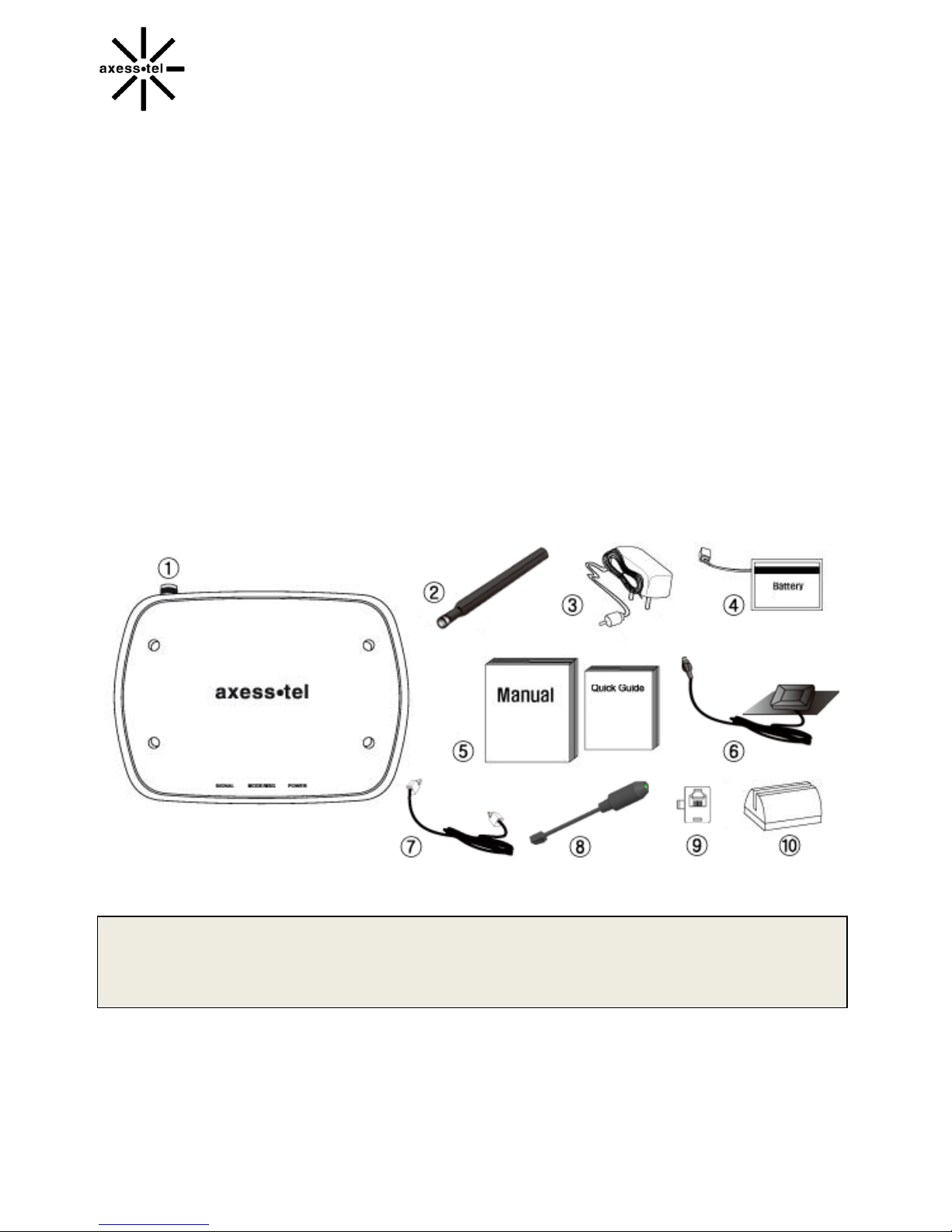
Package Content………….......................5 Restricting Outgoing Calls….................20
Factory Reset…….……….....................21
BASIC INSTALLATION TTY/TDD
Internal Battery Installation......................6 Mode Setting…….……….....................21
Setting Up the Terminal...........................6
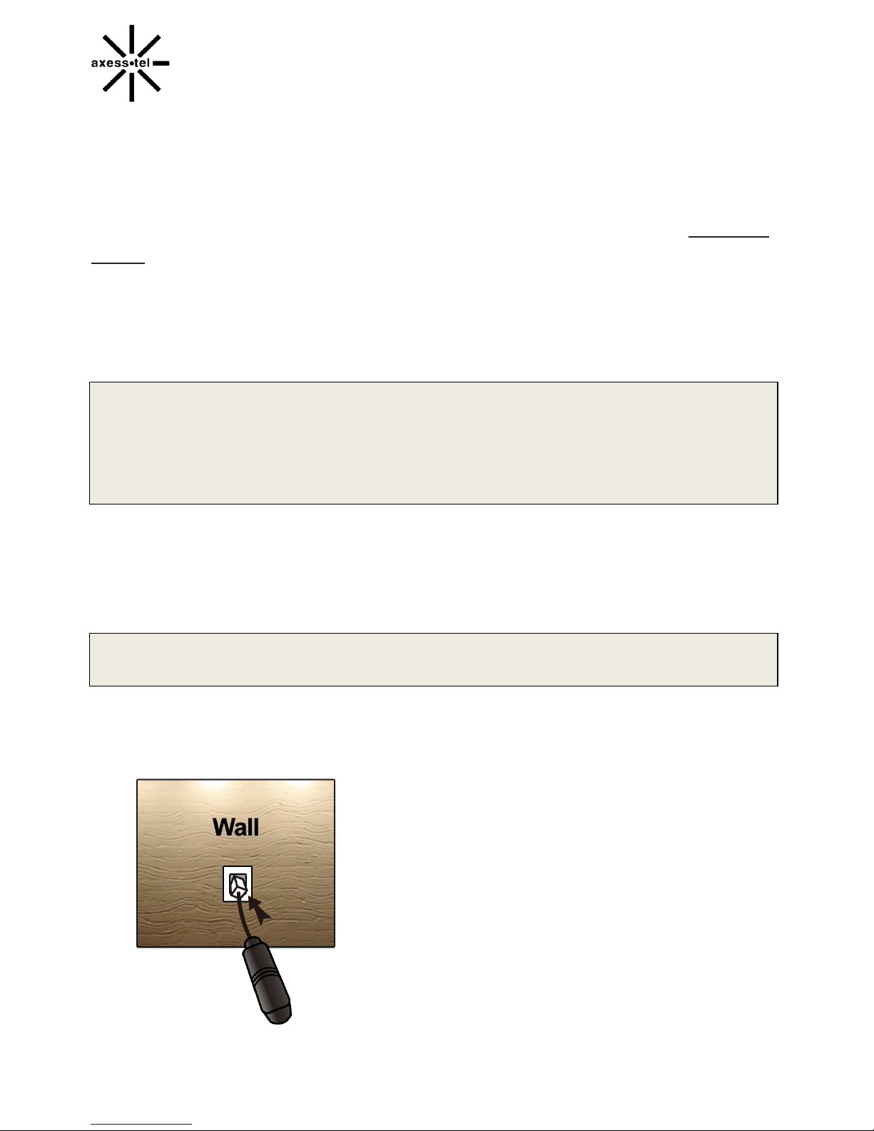
Wall Jack Tester……...............................7 OPTIONAL FEATURES
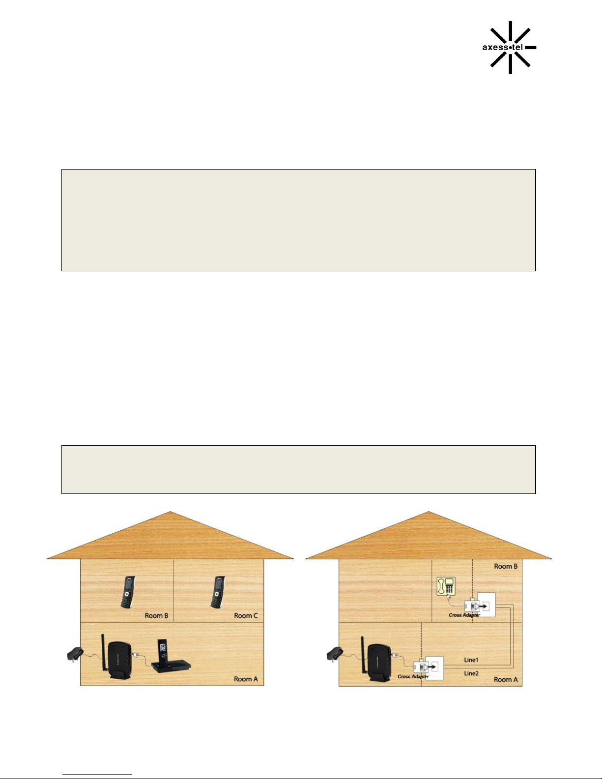
RJ11 Cross Adaptor.................................8 Call Waiting…………….........................23
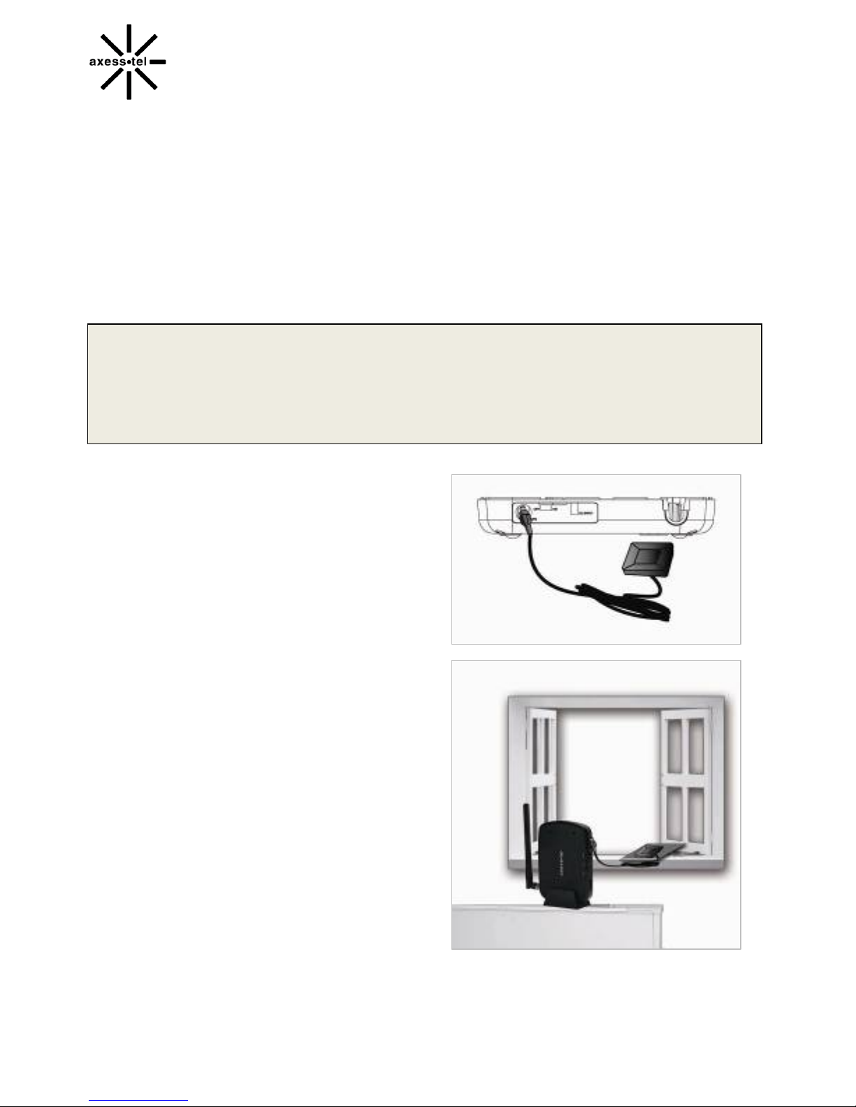
A-GPS for E911…...................................9 Three-Way Calling……….….................23
Wall Mount Installation...........................10 Voice Mail Service..………....................23
LED Indicators........................................11
Audible Indicators……............................12 MISCELLANEOUS
Menu Option Table...............................25
BASIC OPERATION Troubleshooting.....................................26
Power On/Off…………..........................14 Specification..........................................27
Making Calls…………...........................14
Receiving Calls.....................................15
ADVANCED FEATURES
SOUND
Adjusting Voice Volume……………...….17
Adjusting Alert Tone Volume.................17
Setting One Minute Volume..................17
Setting Voice Privacy Alert....................17
Setting Connection Alert……….............18
GENERAL
Setting Caller ID and Call Waiting ID.....18
Setting Auto Send Time…………….……18

4
SAFETYPRECAUTIONS
1. Avoid placing the terminal in a dusty location, or near a source of gas or fire.
2. Do not shake, hit or drop the terminal.
3. To clean the outside of the terminal, use only a soft, dry cloth, as chemicals such as alcohol,
benzene or acetone can damage the surface of the terminal.
4. Do not twist or pull the cables.
5. Do not disassemble the terminal.
6. Do not use the power adapter if:
- The power cord is damaged.
- The adapter has been damaged in any way.
7. Use only the AXESSTEL provided power adapter. Do not use the AXESSTEL power adapter for
any other purposes.
8. Use only the AXESSTEL provided antenna. Do not use the antenna for any other purposes.
9. Frequency and length of use can affect the life of the self-charging battery. Contact your point of
sale’s customer service department if the battery is not operating properly.
10. Use only the designated self-charging battery. Dispose of exhausted batteries properly.
Never discard a battery in or near a fire or flame.
11. Do not use the terminal near water, for example, near a bathtub, sink, wet basement, or swimming
..pool.
NOTE: The input voltage and the shape of the power plug may vary from country to country.
NOTE: Use wired or cordless telephones compatible to FCC part 68 only. Non-compliant
telephones may not work properly.

5
PACKAGECONTENTS
After opening the package, check to make sure that you have all the parts shown below.
If any item is missing or broken, please call your service provider’s support center.
①
Axesstel 1x Fixed Wireless Terminal
②
CDMA Dipole Antenna
③
Power Adapter (Input: AC100-240V, 50/60Hz / Output:5V/2A)
④
Backup Battery
⑤
User Manual and Quick Guide
⑥
GPS Antenna with Cable and Pad
⑦
RJ-11 Phone Cord
⑧
PSTN Tester
⑨
RJ-11 Cross Adaptor
⑩
Desktop Stand
CAUTION
Use the provided power adapter only. Using other power adapter may cause
permanent damage to the terminal.

6
BASICINSTALLATION
INTERNAL BATTERY INSTALLATION
This TX240G operates by receiving electricity from an electrical outlet or internal battery.
1. Open the battery cover on the bottom side of the terminal.
2. Connect the Battery power cable to the terminal.
3. Insert the battery pack in the right position between the hold bars.
4. Close the battery cover.
SETTING UP THE TERMINAL
1. Connect the antenna by screwing it into
the TNC connector on the back of the terminal.
2. Connect a wired or cordless telephone to the
terminal using the RJ-11 phone cord.
NOTE: Use wired or cordless telephones compatible to FCC part 68 only. Non-compliant
telephones may not work properly.
3. Plug the AC adapter plug into the DC 5V jack of the Terminal.
4. Plug the AC adapter plug into an appropriate electrical outlet.

7
Connecting the Terminal to Home Phone Wall Outlet.
The TX240 can be connected to a home wall phone jack to generate a dial tone service throughout
the entire home and allow users to use phones from any other home wall phone jack. Please verify
that the home wall phone jacks do not have existing active telephone service and that they are not
powered. Before connecting the terminal to home wall jack, please test with the included “Wall Jack
Tester”.
WALL JACK TESTER (PSTN Line Tester)
The wall jack tester will verify if the wall phone jack is powered by existing or previous landline phone
service.
IMPORTANT NOTE
DO NOT CONNECT YOUR TERMINAL TO A WALL JACK IF PSTN LINE IS STILL IN SERVICE.
Connecting the terminal to the live wall jack may interfere with the existing phone service
and damage the terminal.
1. Plug the tester into the wall jack.
2. If tester’s Green colored LED illuminates (ON), your PSTN line is still active and powered. In this
case, contact your existing or previous landline phone service provider to disconnect the phone
service and power.
NOTE: Alternately, 2-line cross adapter may be used to bypass the powered first phone line. Please
.see next section, using 2-line cross adapter.
3. If Green colored LED does not illuminate, the wall phone jack is not powered and you can safely
connect your terminal to wall jack.
[LED OFF – line is safe to use]

8
RJ-11 CROSS ADAPTOR (Line1toLine2BypassAdapter)
If the first line of the phone line is live and has power, you may still be able to use the terminal through
your home phone wiring by using the RJ-11 cross adapter. Line 1 uses the middle two pins on the RJ-
11 cable. Line 2 uses the outer two pins on the RJ-11 connector.
IMPORTANT NOTE
Some house wirings may only have line 1. Some houses may have both line 1 and line 2
wires live. In such cases, please do not connect the terminal to your house wall jack.
Instead, please consider using multi-handset cordless phone. Connect the base of the
cordless phone directly to the terminal using RJ-11 cable.
1. Before connecting the terminal, test the line 2 in your house by plugging the cross adapter into the
wall jack. Then plug the Wall Jack Tester into the back of the cross adapter. If the LED is lit, line
2 is also live.
2. If the line 2 is not live, connect one of the cross connector between the terminal and wall-jack. This
will convert the terminal output to line 2 of the in-wall wiring.
3. Connect another cross connector between another wall jack and corded/cordless phone in another
room. Check if there is dial tone or busy tone on the line.
4. If no tone is heard, please check if the terminal is turned on properly. If the problem persists, it
may be possible that the home wiring line 2 is not available.
NOTE: The default packaging may or may not include the cross adaptors. Cross adapter may be
called a “2-Line Splitter” and should be readily available at local electronic or office supply
stores.

9
A-GPSforE911
Your terminal supports an A-GPS feature to meet a FCC 911 mandate, which makes the location of
the terminal available to 911 operators in the case of emergency situations. During the emergency call,
all the LEDs on the terminal will blink and your location can then be determined by the 911 operator. In
order to increase the location accuracy, the external GPS antenna must be connected to the terminal
and positioned at a location that can receive satellite signals, such as outside the home or building or
near a window without obstructions to the sky.
IMPORTANT NOTE
The accuracy of the A-GPS location will significantly degrade if the A-GPS antenna is not
connected to properly or located indoor or at a place with obstruction to the sky. In such
cases, the emergency dispatcher will not be able to accurately locate your position. The A-
GPS signal and location accuracy can be dependent on many factors and cannot be
guaranteed.
1. Connect the A-GPS antenna to the SMA
connector on the terminal.
2. Place the Magnetic Pad at a location that
has no obstruction to the sky, such as
outdoors or near a window.
3. Put the A-GPS antenna on the magnetic pad
and position the antenna to face outside.

10
WALL MOUNT INSTALLATION
1. Mark two mounting hole locations on a wall to match the screw holes on the back of the terminal.
2. Drill two holes and put screws at the marked locations.
3. Tighten the screws until the head is about 5mm from the wall.
4. Plug in the AC power connector and route the power cord in the groove, if needed. Connect
antenna.
5. Hang the terminal on the screws using the two holes on the back.
6. Push the terminal down until the unit is firmly locked into place.

11
GETTINGTOKNOWTHETERMINAL
LED INDICATORS
Item Color Status Description
POWER
Green
Solid
In Battery Mode: Fully Charged Full
In Adaptor Mode: Connected
Blinking Charging
Orange
Solid Mid Battery Level
Blinking Battery Error
Red
Solid Low Battery
Blinking Low Battery Warning
Off - No Battery
SIGNAL
Green Solid Excellent Signal
Orange Solid Good Signal
Red Solid Low Signal
OFF - No Service
MODE/MSG
Green
Solid Off-Hook or In Use
Blinking Incoming Call
Orange Blinking Voice Mail Waiting
E911 Call
All LEDs Blinking All LEDs blink during emergency call

12
AUDIBLE INDICATIORS
No Tone Cadence Remark
1 Dial Tone
Continuous beep
330ms ON / OFF
660ms ON / OFF
Terminal is in service area and
can make calls.
2 Busy Tone Beep - beep - beep
0.5s ON / 0.5s OFF Recipient line is busy
3 Howler Tone
High pitched beep
(1400+2060Hz) 0.1S ON
(2450+2600Hz) 0.1S OFF
Phone receiver is off the hook for
more than specified duration
4 No Service Tone
Long beep + pause
1.5s ON
800ms OFF
Terminal cannot make or receive
calls (No signal)
5 Function Confirm Tone
Escalating bee – bee -beep
1046Hz: 350ms ON
1328Hz: 350ms ON
1567Hz: 350ms ON
Used when accessing menu.
Menu selection or configuration
successful
6 Function Error Tone Three Short Beeps
Used when using menu.
Menu selection or configuration
not successful
7 Outgoing Call
Restriction Tone
800ms ON
200ms OFF
Terminal is configured to block
outgoing call (incoming calls are
permitted)
8 Voice Mail Indicate Tone 0.1s ON
0.1s OFF(One Time)
9 One Minute Alert Tone Short beep
0.1s(One Time)
10 Low Battery Alert Tone
Bee – beep --- bee – beep
0.1s ON, 10ms OFF
0.1s ON, 1s OFF

13
Basic Operation
POWER ON/OFF
MAKING CALLS
RECEIVING CALLS

14
POWERON/OFF
The power switch is located on the back side of the terminal
1. Turn on the unit by moving switch to ON position.
2. Turn off the unit by moving switch to OFF position.
NOTE: When you turn on the terminal, it automatically searchesforcellularservice.
After successfully acquiring cellular service, the Signal LED turns to Green, Orange or Red
depending on signal strength.
MAKINGCALLS
1. Check if the terminal is turned on.
2. Pick up the handset of the phone.
3. If you hear a dial tone, dial the desired telephone number by using the wired or cordless
telephone’s keypad.
NOTE: You can dial a phone number with a maximum of 32 digits, including □
* and □
#.
4. Wait for about 3 seconds until the call is automatically processed by the terminal. (Auto Dial Time
can be configured from 3 seconds to 9 seconds, or turned-off).
NOTE: If “□
# as Send Key” feature is enabled, press the □
# button to process the call
immediately after entering the dialed number. Default setting is OFF. Please refer to the
page 19 for “Using □
# as Send Key”.
5. When the other recipient answers, begin conversation.
NOTE: If Connection Alert is turned on, a beep is heard when the call is connected. The default
settingisOFF.
6. To hang up, put the phone receiver back on the phone hook or press the TALK or OFF button on
your phone.

15
RECEIVINGCALLS
The wired or cordless telephone(s) connected to the terminal ring when an incoming call
comes in.
1. Pick up the phone receiver to answer the call.
2. To disconnect after the call is finished, place the handset on the phone hook or press the TALK or
OFF button on your phone.
NOTE 1: If using cordless phone, press TALK or ON button to answer the phone call.
.Refer to the cordless phone user manual for instruction.
NOTE 2: Make sure that the attached telephone(s) ringers are enabled.
NOTE 3: When there is another incoming call during an already active phone call, press any
.key on the numeric keypad to answer the call.

16
Advanced Features
SOUND
○ADJUSTING VOICE VOLUME
○ADJUSTING ALERT TONE VOLUME
○SETTING ONE MINUTE ALERT
○SETTING VOICE PRIVACY ALERT
○SETTING CONNECTION ALERT
.GENERAL
○SETTING CALLER ID
○CALL WAITING ID
○CALLER NAME DISPLAY
○SETTING AUTO SEND TIME
○USING # AS SEND KEY
○SETTING DTMF LENGTH
.SECURITY
○CHANGING LOCK CODE
○RESTRICTING OUTGOING CALLS
○FACTORY RESET
.TTY/TDD
○MODE SETTING

17
SOUND
ADJUSTING VOICE VOLUME
You can control the volume level of the terminal.
1. Pick up the handset and listen to the dial-tone.
2. Press □
*□
*□
1□
1□
* to raise the voice volume.
3. Press □
*□
*□
1□
1□
# to lower the voice volume.
4. A confirmation beep will sound.
NOTE 1: Some phones may have their own volume control. Use both the terminal and the phone
.volume controls to optimize the sound level.
NOTE 2: Volume cannot be adjusted while a conversation is in progress.
ADJUSTING ALERT TONE VOLUME
1. Pick up the handset.
2. Press □
*□
*□
1□
2□
* to raise the alert tone volume.
3. Press □
*□
*□
1□
2□
# to lower the alert tone volume.
SETTING ONE MINUTE ALERT
When this feature is enabled, a discrete tone is generated at each one minute interval on the
receiver during a conversation for both incoming and outgoing calls. This tone is to help the
user keep track of the phone usage.
To change the setting:
1. Pick up the handset.
2. Press □
*□
*□
1□
3□
# to enable the feature.
3. Press □
*□
*□
1□
3□
* to disable the feature.
SETTING VOICE PRIVACY ALERT
If enabled, a beep is generated when Voice Privacy is on.
To change the setting:
1. Pick up the handset.
2. Press □
*□
*□
1□
4□
# to enable the feature.
3. Press □
*□
*□
1□
4□
* to disable the feature.

18
SETTING CONNECTION ALERT
If enabled, a discrete tone is generated on the receiver when a call is connected.
To change the setting:
1. Pick up the handset.
2. Press □
*□
*□
1□
5□
# to enable the feature.
3. Press □
*□
*□
1□
5□
* to disable the feature.
NOTE: The default setting may depend on the service provider.
GENERAL
SETTING CALLER ID MODE
If your phone connected to the terminal is caller ID enabled, you can set the terminal to display
the caller identification number or name on the LCD display of the wired or cordless phone.
To change the setting:
1. Pick up the handset.
2. Press □
*□
*□
2□
1□
0□
# to disable the Caller ID feature.
3. Press □
*□
*□
2□
1□
1□
# to enable DTMF Standard type.
4. Press □
*□
*□
2□
1□
2□
# to enable FSK (Bellcore) type.
NOTE: The default setting of Caller ID is FSK.
CALL WAITING ID
The Call Waiting ID feature allows the display of the second caller’s number while already in a
conversation (call waiting). This feature works only with FSK Caller ID setting. In order to use this
feature, the corded/cordless phone must support caller ID and call waiting ID, also known as type II
caller identification.
CALLER NAME DISPLAY
This feature allows the display of the caller’s name on the corded or cordless phones that support
alpha-numeric display for caller name display. This is a network dependent feature and works only if
your service provider supports it. This feature may require an upgrade to premium service or an
additional fee.

19
SETTING AUTOSEND TIME
Similar to a landline phone, the terminal automatically makes the call shortly after the user
finishes entering the phone number. To change the setting:
1. Pick up the handset.
2. Press □
*□
*□
2□
2 Then press □
3,
□
9 or□
0 and press □
#.
For example, to set the auto-send time to 5 seconds, press □
*□
*□
2□
2□
5□
#.
NOTE 1: 0 value disables auto-send. If disabled, the user must press □
# to make a call. □
#
functions as a SEND key on the mobile phone. If auto-send time is set to 0, then the
□
# as SEND feature is automatically enabled.
NOTE 2: The default auto send time is 3 seconds.
USING □
#AS SEND KEY
Similar to mobile phones, pressing the
□
#
key after entering the phone number can act as SEND
key.
This feature can be enabled or disabled. To change the setting:
1. Pick up the handset.
2. Press □
*□
*□
2□
3□
# to enable the feature.
3. Press □
*□
*□
2□
3□
* to disable the feature.
Note: The default setting is OFF. If the Auto-Send Time is set as 0, then “□
# as SEND key”
feature is automatically enabled.
SETTING DTMF LENGTH
Some ARS (Automatic Response Service) require short or long DTMF tones depending on the
system. To change the setting:
1. Pick up the handset.
2. Press □
*□
*□
2□
4□
# to select Short DTMF tone.
3. Press □
*□
*□
2□
4□
* to select Long DTMF tone.

20
SECURITY
CHANGING LOCK CODE
The lock code prevents the terminal from being used by an unauthorized person without
permission. The default lock code is □
0□
0□
0□
0.
To change the lock code:
1. Pick up the handset.
2. Press □
*□
*□
3□
1.
3. Enter the old 4 digit lock code. For example □
0□
0□
0□
0 , a short beep will sound as confirmation. If
not correct, an error tone will sound and the terminal will return to standby mode.
4. Enter the new 4 digit lock code followed by □
# . For example □
1□
2□
3□
4□
# , another short beep
will sound as confirmation.
5. Re-enter the new 4 digit lock code followed by □
# . For example □
1□
2□
3□
4□
# , another beep will
sound as confirmation. If not correct, error tone will sound and the terminal will return to standby
mode.
For example, to change the lock code from □
0□
0□
0□
0 to□
1□
2□
3□
4 , press
□
*□
*□
3□
1
□
0□
0□
0□
0
□
1□
2□
3□
4□
#
□
1□
2□
3□
4□
#.
RESTRICTING OUTGOING CALLS
This feature can be used to block outgoing calls from being made. But incoming call can still
be received. To change the setting:
1. Pick up the handset.
2. Press □
*□
*□
3□
2.
3. Enter 4 digit lock code.
4. Press □
# to enable or □
* to disable.
NOTE 1: The default lock code is □
0□
0□
0□
0 . To change, refer to “Changing Lock Code” section.
NOTE 2: If someone tries to make a call when outgoing call restriction is enabled, the terminal
sounds a beep and howler tone.
Other manuals for TX240G
1
Table of contents
Other Axesstel Touch Terminal manuals