Axiom AX2065P User manual

AX2065P
Passive Vercal Array Loudspeaker
USER MANUAL
revision 2023-07-19

2
Watch for these symbols:
The lightning ash with arrowhead symbol within an equilateral triangle is intended to alert the user to the presence of uninsulated
“dangerous voltage” within the product’s enclosure, that may be of sucient magnitude to constute a risk of electric shock to
persons.
The exclamaon point within an equilateral triangle is intended to alert the user to the presence of important operang and
maintenance (servicing) instrucons in the literature accompanying the appliance.
IMPORTANT SAFETY INSTRUCTIONS
1. Read these instrucons.
2. Keep these instrucons.
3. Heed all warnings.
4. Follow all instrucons.
5. Do not use this apparatus near water.
6. Clean only with dry cloth.
7. Do not block any venlaon openings. Install in accordance with the manufacturer’s instrucons.
8. Do not install near any heat sources such as radiators, heat registers, stoves, or other apparatus (including ampliers) that
produce heat.
9. Do not defeat the safety purpose of the polarized or grounding-type plug. A polarized plug has two blades with one wider than
the other. A grounding-type plug has two blades and a third grounding prong. The wide blade or the third prong are provided
for your safety. If the provided plug does not t into your outlet, consult an electrician for replacement of the obsolete outlet.
10. Protect the power cord from being walked on or pinched, parcularly at plugs, convenience receptacles, and the point where
they exit from the apparatus.
11. Only use aachments/accessories specied by the manufacturer.
12. Use only with the cart, stand, tripod, bracket, or table specied by the manufacturer, or sold with the apparatus. When a cart
is used, use cauon when moving the cart/apparatus combinaon to avoid injury from p-over.
13. Unplug this apparatus during lightning storms or when unused for long periods of me.
14. Refer all servicing to qualied service personnel. Servicing is required when the apparatus has been damaged in any way, such
as power supply cord or plug is damaged, liquid has been spilled or objects have fallen into the apparatus, the apparatus has
been exposed to rain or moisture, does not operate normally, or has been dropped.
15. Warning: to reduce the risk of re or electric shock, do not expose this apparatus to rain or moisture.
16. Do not expose this equipment to dripping or splashing and ensure that no objects lled with liquids, such as vases, are placed
on the equipment.
17. To completely disconnect this apparatus from the ac mains, disconnect the power supply cord plug from the ac receptacle.
18. The mains plug of the power supply cord shall remain readily operable.
19. This apparatus contains potenally lethal voltages. To prevent electric shock or hazard, do not remove the chassis, input
module or ac input covers. No user serviceable parts inside. Refer servicing to qualied service personnel.
20. The loudspeakers covered by this manual are not intended for high moisture outdoor environments. Moisture can damage
the speaker cone and surround and cause corrosion of electrical contacts and metal parts. Avoid exposing the speakers to
direct moisture.
21. Keep loudspeakers out of extended or intense direct sunlight. The driver suspension will prematurely dry out and nished
surfaces may be degraded by long-term exposure to intense ultra-violet (UV) light.
22. The loudspeakers can generate considerable energy. When placed on a slippery surface such as polished wood or linoleum,
the speaker may move due to its acouscal energy output.
23. Precauons should be taken to assure that the speaker does not fall o a stage or table on which it is placed.
24. The loudspeakers are easily capable of generang sound pressure levels (SPL) sucient to cause permanent hearing damage
to performers, producon crew and audience members. Cauon should be taken to avoid prolonged exposure to SPL in excess
of 90 dB.
This marking shown on the product or its literature, indicates that it should not be disposed with other household wastes at the end
of its working life. To prevent possible harm to the environment or human health from uncontrolled waste disposal, please separate
this from other types of wastes and recycle it responsibly to promote the sustainable reuse of material resources. Household users
should contact either the retailer where they purchased this product, or their local government oce, for details of where and
how they can take this item for environmentally safe recycling. Business users should contact their supplier and check the terms
and condions of the purchase contract. This product should not be mixed with other commercial wastes for disposal.

3
LIMITED WARRANTY
Proel warrants all materials, workmanship and proper operaon of this product for a period of two years from the original date of purchase. If any
defects are found in the materials or workmanship or if the product fails to funcon properly during the applicable warranty period, the owner
should inform about these defects the dealer or the distributor, providing receipt or invoice of date of purchase and defect detailed descripon.
This warranty does not extend to damage resulng from improper installaon, misuse, neglect or abuse. Proel S.p.A. will verify damage on returned
units, and when the unit has been properly used and warranty is sll valid, then the unit will be replaced or repaired. Proel S.p.A. is not responsible
for any “direct damage” or “indirect damage” caused by product defecveness.
• This unit package has been submied to ISTA 1A integrity tests. We suggest you control the unit condions immediately aer unpacking it.
• If any damage is found, immediately advise the dealer. Keep all unit packaging parts to allow inspecon.
• Proel is not responsible for any damage that occurs during shipment.
• Products are sold “delivered ex warehouse” and shipment is at charge and risk of the buyer.
• Possible damages to unit should be immediately noed to forwarder. Each complaint for package tampered with should be done within eight
days from product receipt.
CONDITIONS OF USE
Proel do not accept any liability for damage caused to third pares due to improper installaon, use of non-original spare parts, lack of
maintenance, tampering or improper use of this product, including disregard of acceptable and applicable safety standards. Proel strongly
recommends that this loudspeaker cabinet be suspended taking into consideraon all current Naonal, Federal, State and Local regulaons. The
product must be installed be qualied personal. Please contact the manufacturer for further informaon.
DECLARATION OF CONFORMITY
The product is in compliance with:
RoHS Direcve 2011/65/EU and 2015/863/EU, WEEE Direcve 2012/19/EU.
The product is in compliance with:
S.I. 2012/3032 The Restricon of the Use of Certain Hazardous Substances in Electrical and
Electronic Equipment Regulaons 2012

4
INTRODUCTION
The AX2065P Vercal Line Array element is designed for a wide range of sound reinforcement applicaons where a exible and
easy to use vercal array systems is needed. The AX2065P has been designed both for rental live sound applicaons and for
xed installaons and has been engineered for the simplest use possible but without sacricing anything in sound quality and
performance.
The high frequency range is reproduced by a low-distoron compression driver, equipped with very light-weight Titanium
diaphragms and a special new suspension design for very natural sound. A transmission line wave-forming waveguide has been
used to load the HF driver, in order to provide a detailed and natural sound and to achieve a long-distance HF projecng capacity.
The two 6.5” woofers employed in the reproducon of the mid-bass range are equipped with very light-weight cones and rubber
suspension to extend the low frequency response. The lightness of the diaphragm is furthermore improved by the use of aluminium
voice coil instead of convenonal copper. This ensure a fast reproducon of the mid range and of mid-bass musical passages,
improving also the thermal capacity of the voice coil and, consequently, controlling the overall power compression. The two 6.5”
woofers are back loaded by a short hybrid transmission line that minimizes the eect of the box resonances and eliminates the
“boxy” mid-bass sound commonly obtained from regular bassreex enclosures. The crossover lter approach is based on a “Constant
Power” technique. Thanks to a parcular phase combinaon between the two ways around the crossover frequency, this approach
is able to provide a very stable horizontal coverage and a very stable o-axys sound image, also minimizing unwanted eects around
the crossover frequency. The further applicaon of phase linearizaon techniques, combined to constant power crossover, yield a
linear phase response and a coherent me response. This allows for a natural percepon of acousc instruments and voices and
for an improved depth of the sound image.
TECHNICAL SPECIFICATION
SYSTEM INPUT CONNECTION
System’s Acousc Principle
Line Array Element
Short Transmission Line LF Back Loading
Acousc Transmission Line HF Waveguide
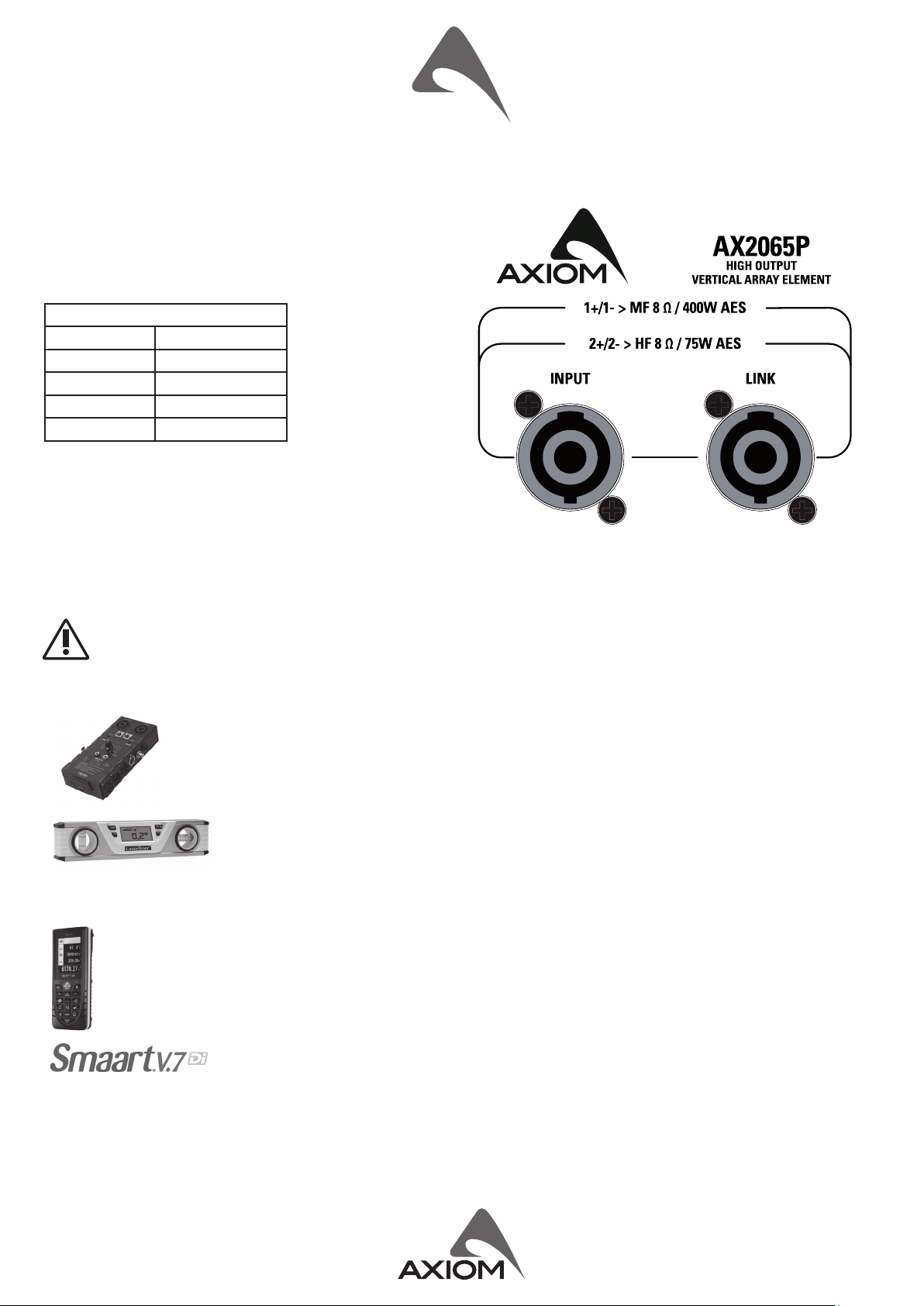
Connector Type Neutrik® Speakon® NL4 x 2
Input Wiring LF = Pin 1+/1-; HF = Pin 2+/2-
POWER HANDLING
Frequency Response (±3dB) 80 Hz – 18 KHz (Processed) Continuous AES Pink Noise
Power 400 W (LF) + 75 W (HF)
Nominal Impedance 8Ω (LF) + 8Ω (HF)
Minimum Impedance 7.2 Ω @ 340Hz (LF); 7Ω @ 2.5kHz (HF) Program Power 800 W (LF) + 150 W (HF)
Horizontal Coverage Angle 110° (-6dB)
LF Power Compression
@ -10 dB Power (70 W) = 0.7 dB
@ -3 dB Power (350 W) = 1.8 dB
@ 0 dB Power (700 W) = 3.5 dB
Vercal Coverage Angle 12° (-6dB)
Sensivity (2.83 V @ 1m, 2 Pi) 99 dBSPL (LF); 108 dBSPL (HF)
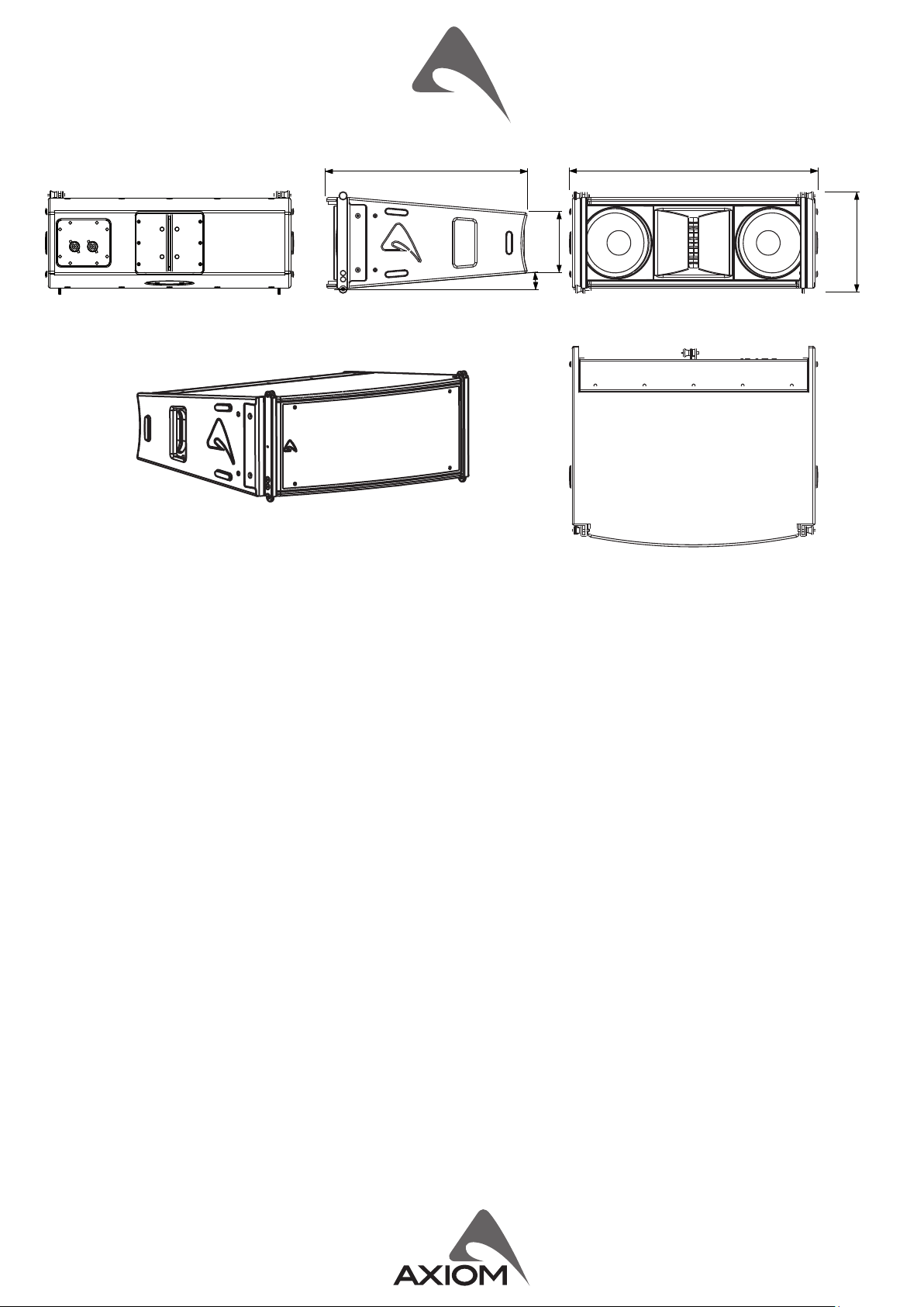
Maximum Peak SPL @ 1m 129 dB ENCLOSURE & CONSTRUCTION
TRANSDUCERS Dimensions (W x H x D) 583 mm (22.95”) x 244 mm (9.60”) x 481
mm (18.93”)
LF
Two 6.5” (165 mm), 1.5” (38 mm)
aluminium voice coil, 16Ω each,
paralleled
Taper angle 5°
Construcon 15 mm, reinforced Phenolic Birch
HF
One 1.4” drivers, 2.5” (64 mm)
edgewound voice coil, tanium
diaphragm, 8Ω
Paint High resistance, water based paint
Front Suspension Aluminium Fast Link structure
Back Suspension High Strength Steel
Net Weight 19.2 Kg (42.32 lbs.)
INDEX
INTRODUCTION ...........................4
TECHNICAL SPECIFICATION ..................4
MECHANICAL DRAWING ....................5
OPTIONAL ACCESSORIES ....................5
SPARE PARTS ..............................5
INPUT ...................................6
LINK .....................................6
PREDICTION SOFTWARE: EASE FOCUS 3 ........7
BASIC INSTALLING OPERATION ...............7
FLY BAR AND ACCESSORIES ..................9
STACKED INSTALLATION ....................12
PRESET USING EXAMPLE:
STANDARD INSTALLATION ..................12
SYSTEM PROCESSING BASIC INSTRUCTIONS ....13
STANDARD PRESET:
2065_4+1_ST01.pcf .......................13
LONG THROW PRESET:
2065_4+1_LT01.pcf .......................13
SINGLE/DOWN-FILL PRESET:
2065_4+1_SD01.pcf ......................13
EXAMPLE OF INSTALLATION IN
A THEATRE WITH BALCONY .................14
PRESET OPERATIONS ......................14
IMPORTANT INSTRUCTIONS TO USE GROUPS ...14
EDIT PARAMETERS ........................14

5
MECHANICAL DRAWING
OPTIONAL ACCESSORIES
AXCASE05 Carrying Case for 4 box unit + Flying Bar KPTSW215 Fly bar for Axiom AX2065 and SW215 Loudspeakers
AXCASE06 Carrying Case for 4 box unit KPTAX2065 Fly bar for 6 MAX Axiom AX2065 Loudspeakers only
NL4FXX-W-L Neutrik Speakon® PLUG for OD 10-16mm AXFEETKIT Kit Of 6pcs BOARDACF01 M10 foot for stacked installaon
AX2065A Acve vercal array loudspeaker KPAX265 Pole Adaptor
SW215P Passive Subwoofer KP010 0° to 10° lt adaptor
SW215FP Flyable Passive Subwoofer DHSS10M20 Sub-Speaker ø35mm Pole with M20 screw
PC260 2 in 6 out digital loudspeaker processor RAINCOV2065 Rain cover for input sockets
USB2CANDV2 Dual output PRONET network converter
see hp://www.axiomproaudio.com for detailed descripon and other available accessories.
SPARE PARTS
NL4MP Neutrik Speakon® panel socket
94SPI2265 Locking Pin for AX2265
PLG716 Straight Shackle 16 mm for Fly bar
91CRAIN3 Crossover/protecon module
98AXM6W16 6.5’’ woofer - 1.5” VC - 16Ω
98DRI2065 1.4’’ compression driver - 2.4” VC - 8Ω
98MBN2065 tanium diaphragm for 98DRI2065 HF driver
48.1 cm
18.93"
58.3 cm
22.95"
24.4 cm
9.60"
5°
14.5 cm
5.70"

6
INPUT
Power input for the external amplier. The AX2065P does not include a passive crossover for ltering the signal, but only an internal
protecon that applies a gentle high-pass ltering and a limitaon for excessive power on the HF secon. The connecons are the
following:
INPUT - LINK
NL4 pin number internal connecon
1+ LF+
1- LF-
2+ HF+
2- HF-
LINK
Power output in parallel with the INPUT socket for connecng the unit to another speaker.
The number of AX2065P cabinets that can be connected in parallel depends on the amplier load capacity.
WARNING: In case of using the AX2065P passive module linked with an AX2065A acve module DO NOT LINK ANY OTHER
AX2065P.
Useful tools to set up properly a vercal array system
This is a list of tools that can be very useful to set properly a vercal array system.
CABLE TESTER
It is a good pracce to check all cables before each installaon,
because even one faulty cable can compromise heavily the
system performance.
INCLINOMETER WITH LEVER
This tool can be used to verify the vercal array angle. It can
be used at the top or at the boom of the array In this case
you have to sum all splay angles, so the maximum precision is
needed for aiming the vercal array, parcularly for long throw
applicaons.
LASER DISTANCE METER
This instrument can be useful to measure the height of the
vercal array and to know the distance between FOH-Subs and
FOH-Array for seng the delay me.
SMAART or similar acousc measurement system
These are useful to measure delays, phase and response of the
system.

7
PREDICTION SOFTWARE: EASE FOCUS 3
To aim correctly a complete system we suggests to use always the Aiming Soware - EASE Focus 3:
The EASE Focus 3 Aiming Soware is a 3D Acousc Modelling Soware that serves for the conguraon and modelling of Line
Arrays and convenonal speakers close to reality. It only considers the direct eld, created by the complex addion of the sound
contribuons of the individual loudspeakers or array components.
The design of EASE Focus is targeted at the end user. It allows the easy and quick predicon of the array performance in a given
venue. The scienc base of EASE Focus stems from EASE, the professional electro- and room acousc simulaon soware developed
by AFMG Technologies GmbH. It is based on the EASE GLL loudspeaker data le required for its use. The GLL le contains the data
that denes the Line Array with regard to its possible conguraons as well as to its geometrical and acouscal properes.
Download the EASE Focus 3 app from the AXIOM website at hps://www.axiomproaudio.com/ clicking on downloads
secon of the product.
Use the menu opon Edit / Import System Denion File to import the GLL le, the detailed instrucons to use the program are
located in the menu opon Help / User’s Guide.
Note: Some windows system can require the .NET Framework 4 that can be download from website at hps://focus.afmg.eu/.
BASIC INSTALLING OPERATION
The EASE FOCUS predicon soware is the tool that allows you to evaluate your installaon both to meet the acousc requirements
of the project and also to suspend or stack AX2065 systems, the program allows you to simulate the rigging pinpoint on the y bar
to obtain the calculated splay angle of the enre line array system and of the individual angles between each loudspeaker element.
The following examples shows how to operate correctly to link the loudspeaker box and to suspend or stack the whole system safely
and surely, read these instrucons with extreme aenon:
WARNING! CAREFULLY READ THE FOLLOWING INSTRUCTIONS AND CONDITION OF USE:
• This loudspeaker is designed exclusively for Professional audio applicaons. The product must be installed by qualied personal
only.
• Proel strongly recommends that this loudspeaker cabinet be suspended taking into consideraon all current Naonal, Federal,
State and Local regulaons. Please contact the manufacturer for further informaon.
• Proel do not accept any liability for damage caused to third pares due to improper installaon, lack of maintenance, tampering
or improper use of this product, including disregard of acceptable and applicable safety standards.
• During assembly pay aenon to the possible risk of crushing. Wear suitable protecve clothing. Observe all instrucons given
on the rigging components and the loudspeaker cabinets. When chain hoists are in operaon ensure that there is nobody directly
underneath or in the vicinity of the load. Do not under any circumstances climb on the array.
• Wind loads
When planning an open-air event it is essenal to obtain current weather and wind informaon. When loudspeaker arrays are own
in an open-air environment, possible wind eects must be taken into account. Wind load produces addional dynamic forces acng
on the rigging components and the suspension, which may lead to a dangerous situaon. If according to the forecast wind forces
higher than 5 b (29-38 Km/h) are possible, the following acons have to be taken:
- The actual on-site wind speed has to be monitored permanently. Be aware that wind speed typically increases with height above
ground.
- Suspension and securing points of the array should be designed to support double the stac load in order to withstand any
addional dynamic forces.
WARNING!
Flying loudspeakers overhead at wind forces higher than 6 b (39-49 Km/h) is not recommended. If the wind force exceeds
7 b (50-61 Km/h) there is a risk of mechanical damage to the components which may lead to a dangerous situaon for
persons in the vicinity of the own array.
- Stop the event and make sure that no person remains in the vicinity of the array.
- Lower and secure the array.
SINGLE PINPOINT FOR
STRAIGHT SHACKLE
KPTSW215 FLOWN PINPOINT
SINGLE PINPOINT FOR
STRAIGHT SHACKLE
KPTAX2065 FLOWN PINPOINT

8
Fly bar suspension and angle setup (centre of gravity)
The gures below show where the normal centre of gravity is with one box or several boxes arranged in a line. Usually the boxes
are arranged to make an arc for the best coverage of the audience, so the center of gravity moves backward. The aiming soware
suggests the ideal suspension pinpoint taking into account this behaviour: x the straight shackle in this posion.
Note that the ideal aiming angle oen doesn’t correspond to the pinpoint: there is oen a lile dierence between ideal aiming
and real aiming and its value is the Delta angle: posive delta angle can be adjusted a lile using two ropes, negave delta angle are
self adjusted a lile because the cables weighs on the back of the array. With some experience it’s possible to consider prevenvely
these required lile adjustments.
During the own set up you can connect the elements of the array to their cables. We suggest to discharge the weight of the cables
from the ying pinpoint by tying them with a texle bre rope, instead of leng them hang freely: in this way the posion of the
array will be much more similar to the simulaon produced by the soware.
Pin locking and splay angles set up
The gures below shows how to insert correctly the locking
pin, always carefully check that each pin is fully inserted and locked in the correct posion. Set up the splay angle between
loudspeakers inserng the pin in the correct hole, please note that the inner holes in the hinge top are for even angles (2, 4, 6 etc.)
while the outer holes are for the odd angles (1, 3, 5 etc.).
HINGE BAR OF PREVIOUS BOX
LOUDSPEAKER SPLAY ANGLES SET UP
USE THIS HOLE TO LOCK THE
HINGE BAR WHEN THE
LOUDSPEAKER IS REST
LOCK THE PIN IN THE
HOLE TO OBTAIN THE
REQUIRED SPLAY
ANGLE.
press and
insert
release and
lock
94SPI2265 LOCKING PIN
KPTSW215 FLY BAR FOR FLOWN ARRAY
CENTRE OF GRAVITY
KPTAX2065 FLY BAR FOR FLOWN ARRAY
CENTRE OF GRAVITY

9
FLY BAR AND ACCESSORIES
The AX2065 Systems are built to allow the suspension of array with variable shape and dimensions. Thanks to a suspension
mechanism designed to be funconal, exible and safe, each system must be suspended or stacked using the KPTSW215 or
KPTAX2065 y bar. The loudspeakers are linked together in a column using a series of couplers integrated in the frame of each
enclosure. Each system is set up properly both acouscally and mechanically only using the aiming soware.
Coupling system in the front does not require any adjustment: using two locking pins, each loudspeaker box is xed to the previous.
The sloed bar in the back is inserted in a U-shaped frame which features a series of numbered holes. Sliding the sloed bar in
the U-shaped frame of the next loudspeaker and inserng a locking pin in one of the numbered holes, it is possible to adjust the
relave splay angle between two adjacent loudspeakers in the array column.
KPTAX2065 y bar maximum capacity is 200 Kg (441
lbs) with the 0° angle. It can support, with a safety
factor of 10:1, up to:
• 6 AX2065 acve or passive (ybar from 0° to 10°)
KPTAX2065 can NOT be used for stacked array.
KPTSW215 y bar maximum capacity is 540 Kg (1190
lbs) with the 0° angle. It can support, with a safety
factor of 10:1, up to:
• 8 AX2065A + 8 AX2065P (ybar from 0° to 10°)
• 12 AX2065A (ybar from 0 to 10°)
• 2 SW215AF + 4 AX2065A + 4 AX2065P (ybar at 0°)
• 2 SW215AF + 8 AX2065A (ybar at 0°)
• 6 SW215AF (ybar from 0° to 5°)
KPTSW215 can be used for stacked array, see further
on this manual.
STRAIGHT SHACKLE 16mm
KPTAX2065 FLY BAR AND ACCESSORIES
SUSPEND HOLES
SUSPEND HOLE
INDICATOR
REAR BOX
PIN ATTACHMENT
FRONT BOX
PIN ATTACHMENT
FRONT BOX
PIN ATTACHMENT
IDENTIFICATION AND
DATA LABEL
BLOCK CAM HOLE
SUSPEND HOLES
SUSPEND HOLE
INDICATOR
REAR BOX
PIN ATTACHMENT
FRONT BOX
PIN ATTACHMENT
FRONT BOX
PIN ATTACHMENT
STRAIGHT SHACKLE 16mm
M10 FOOT FOR
STACKED INSTALLATION
(OPTIONAL)
IDENTIFICATION AND
DATA LABEL
KPTSW215 FLY BAR AND ACCESSORIES

10
Follow the sequence in the gure for xing the y bar at the rst box. Usually this is the rst step before liing up the system. Be
careful to insert properly all the locking pins (2)(3) and the shackle (5) in the right holes as specied by the aiming soware.
When liing the system always proceed gradually step by step, paying aenon to secure the y bar to the box (and the box to the
other boxes) before pulling up the system: this makes easier to insert properly the locking pins. Also when the system is released
down, unlock gradually the pins.
During the liing be very careful to not let the cables enter the space between one enclosure and the other, as their compression
could cut them.
1
1
2
2
3
4
5
KPTAX2065 FLY BAR ASSEMBLY SEQUENCE

11
Follow the sequence in the gure for xing the y bar at the rst box. Usually this is the rst step before liing up the system. Be
careful to insert properly all the locking pins (2)(3) and the shackle (5) in the right holes as specied by the aiming soware.
When liing the system always proceed gradually step by step, paying aenon to secure the y bar to the box (and the box to the
other boxes) before pulling up the system: this makes easier to insert properly the locking pins. Also when the system is released
down, unlock gradually the pins.
During the liing be very careful to not let the cables enter the space between one enclosure and the other, as their compression
could cut them.
1
1
2
2
3
4
5
KPTSW215 FLY BAR ASSEMBLY SEQUENCE

12
KPTSW215 STACKED ARRAY
max splay angle 10°
max splay angle 10°
max splay angle 10°
max splay angle 10°
System: AXIOM AX Series
Company: PROEL S.p.A.
Label: AXIOM AX Series
Position: X=0.00 m
Y=0.00 m
Z=0.80 m
Orientation: Hor=0.0°
Ver=0.0°
Weight: 96,00 kg
Setup: AX2065 StackBar
Box Count: 4
Pinpoint Mode: No Pinpoint
Box Type Gain Rigging Angle Aiming Angle
Box 4 AX2065 STD 0.0 dB 0° 8.0°
Box 3 AX2065 STD 0.0 dB 1° 8.0°
Box 2 AX2065 STD 0.0 dB 2° 7.0°
Box 1 AX2065 STD 0.0 dB 5° 5.0°
(Frame) 0.0°
STACKED INSTALLATION
WARNING!
• The ground where the KPTSW215 Fly bar serving as ground support is placed needs to be absolutely stable and compact.
• In the stack conguraon you have to use the three oponal feet BOARDACF01 (AXFEETKIT kit) and the y bar must be
mounted upside down on the ground.
• Adjust the feet so to lie the bar perfectly horizontal.
• Always secure ground stacked setups against movement and possible pping over.
• A maximum of 4 x AX2065 cabinets with the KPTSW215 Fly bar serving as ground support are allowed to be set up as
ground stack.
Coupling system in the front do not require any adjustment: using two locking pins each loudspeaker box is xed to the previous.
The sloed bar in the back is inserted in a U-shaped frame which features a series of numbered holes. Sliding the sloed bar in
the U-shaped frame of the next loudspeaker and inserng a locking pin in one of the numbered holes, it is possible to adjust the
relave splay angle between two adjacent loudspeakers in the array column.
The opmal splay angles can be simulated using the EASE Focus 3 soware.
PRESET USING EXAMPLE: STANDARD INSTALLATION
In the following gure you can see how to set up a standard audio
system using the minimal conguraon consisng of 2 AX2065 box
and a sub.
In this case some oponal accessories are required: 1x KPAX265, 1x
KP10, 1x DHSS10M20 for each system. The AX2065 box preset must
be used is the DOWN FILL/SINGLE BOX.
KPAX265
MAX 2x AX2065
1x SW215
KP010
DHSS10M20
AX2065 used as convenonal system

13
SYSTEM PROCESSING BASIC INSTRUCTIONS
The AX2065P system does not feature passive lters so it needs an external processor to take care of the ltering, the me alignment
and the speaker protecon. For the system’s processing PROEL PC260 digital loudspeaker processor must be used, loaded with
dedicated presets for the correct system operaon, which oer the best starng point for seng the me alignment, the gain and
the equalizaon. For detailed instrucons about the use of PC260 refer to its user’s manual. The presets can be download from the
AXIOM web site in the AX2065P download secon.
STANDARD PRESET: 2065_4+1_ST01.pcf
This PRESET is suitable for vercal own arrays that may range
from 4 to 8 boxes or for the centre region of a bigger own array.
It can be used also for stacked arrays.
NOTE: in this preset the subwoofer SW215P is placed at the top of
the own array, in case the sub is placed on ground an addional
delay me must be considered (read the PC260 OUT secon
further in this manual).
LONG THROW PRESET: 2065_4+1_LT01.pcf
This PRESET can be used in arrays bigger than 6 or 8 boxes and
loaded in the top 1 or 2 boxes in order to obtain a more even
distribuon of the sound pressure, especially if they point very
far away or to the upper deck of a large theatre.
SINGLE/DOWN-FILL PRESET: 2065_4+1_SD01.pcf
This PRESET, which features a much smoother high frequency
response, can be loaded in the boom boxes (usually 1 or 2 boxes)
of a large own array, in order to reach conveniently the audience
close to the stage. It can be used also for the convenonal system
consisng 1x SW215P at ground and 2x AX2065P on pole.
This preset could be very useful also when the box is used just on
its own as a Front Fill element in the front of very large stages.
System: AXIOM AX Series
Company: PROEL S.p.A.
Label: AXIOM AX Series
Position: X=0.00 m
Y=0.00 m
Z=0.80 m
Orientation: Hor=0.0°
Ver=0.0°
Weight: 96,00 kg
Setup: AX2065 StackBar
Box Count: 4
Pinpoint Mode: No Pinpoint
Box Type Gain Rigging Angle Aiming Angle
Box 4 AX2065 STD 0.0 dB 0° 8.0°
Box 3 AX2065 STD 0.0 dB 1° 8.0°
Box 2 AX2065 STD 0.0 dB 2° 7.0°
Box 1 AX2065 STD 0.0 dB 5° 5.0°
(Frame) 0.0°
System: AXIOM AX Series
Company: PROEL S.p.A.
Label: AXIOM AX Series
Position: X=0.00 m
Y=0.00 m
Z=4.00 m
Orientation: Hor=0.0°
Ver=-5.1°
Weight: 164,30 kg
Setup: SW215 SuspBar
Box Count: 5
Pinpoint Mode: Best Pinpoint
Pinpoint Number: 7
Remaining Vertical Angle: 0.4°
Bottom Angle: 23,1 °
Above Ground: 2,31 m
Box Type Gain Rigging Angle Aiming Angle
(Frame) -5.1°
Box 1 SW215F 0.0 dB 0° -5.1°
Box 2 AX2065 STD 0.0 dB 0° -5.1°
Box 3 AX2065 STD 0.0 dB 1° -6.1°
Box 4 AX2065 STD 0.0 dB 2° -8.1°
Box 5 AX2065 STD 0.0 dB 10° -18.1°
System: AXIOM AX Series
Company: PROEL S.p.A.
Label: AXIOM AX Series
Position: X=10,00 m
Y=0,00 m
Z=8,00 m
Orientation: Hor=0,0°
Ver=-4,3°
Weight: 137,00 kg
Setup: KPTAX2065 Susp
Box Count: 6
Pinpoint Mode: Best Pinpoint
Pinpoint Number: 7
Remaining Vertical Angle: 0,5°
Bottom Angle: 21,2 °
Above Ground: 6,67 m
Box Type Gain Rigging Angle Aiming Angle
(Frame) -4,3°
Box 1 AX2065 LT 0,0 dB 0° -4,3°
Box 2 AX2065 STD 0,0 dB 1° -5,3°
Box 3 AX2065 STD 0,0 dB 1° -6,3°
Box 4 AX2065 STD 0,0 dB 2° -8,3°
Box 5 AX2065 STD 0,0 dB 3° -11,3°
Box 6 AX2065 STD 0,0 dB 5° -16,3°

14
EXAMPLE OF INSTALLATION IN A THEATRE WITH BALCONY
Here below you can see an example of the
use of dierent PRESETS in an AX2065 own
array installed in a big theatre with balcony.
The TOP BOXES of the array are aiming at the
balcony while the DOWN FILL box is aiming at
the audience close to the stage.
TOP BOXES: the power level at the end of
the balcony is lower, as well as the high
frequency level.
DOWN FILL BOXES: the power level in the
proximity of the stage is higher, as well as the
high frequency level.
PRESET OPERATIONS
In order to opmize the array performances for this specic applicaon, the
PRESETS should be loaded in dierent PC260 loudspeaker processors used in
the following way.
Load the STANDARD preset in the rst PC260 processor that drives the ampliers
for the central boxes.
Load the LONG THROW preset in the second PC260 processor that drives the
amplies for the TOP 1 or 2 boxes, in order to compensate the loss of power
level and high frequencies of the program sent to the upper deck of the theatre.
Load the DOWN FILL / SINGLE BOX preset in the third PC260 processor that
drives the ampliers for the BOTTOM box in order to smooth the high frequency
content of the program sent to the audience close to the stage.
NOTE: the audio signal send to all PC260 processors must be the same so their
inputs must be linked with a XLR cable.
NOTE: The outputs 1 and 2 of each PC260 are assigned always to drive the
ampliers for the SW215 subwoofers, so you can use indiscriminately the output
1 and 2 of one of them.
IMPORTANT INSTRUCTIONS TO USE GROUPS
If you use more than one PC260 processor to drive the
same vercal array system as in the example above, you
must always set the same parameters of the input panel for
both processors: levels and delay and any other parameter
must be always the same. The right way to this is the
following:
1) Be sure that each PC260 has not assigned to any device
group.
2) Load the STANDARD, SINGLE/DOWN-FILL, LONG THROW
preset on each dedicated PC260.
3) Assign every PC260 to the same device group.
Now any modicaon made on one PC260 is repeated also
on all the others assigned to the same group.
WARNING: Aer you have assigned all the PC260
to the same group, do not load or save preset, because what you do on one unit will be repeated also on the others (for load and save
operaons you must remove the units from the groups).
EDIT PARAMETERS
In the PC260 presets some parameters can be customized and some other are protected, this
ensure a safe operaon of the system. Here is a brief descripon of customizable parameters:
IN: In this screen you can adjust the input levels, compressors/limiters and delay.
The input range can be opmized in the -30 ÷ +6 dB range. The level is set aer the AD
conversion, so if you have problems with an excessive input signal use the analog PAD buon
on the PC260 back panel.
The compressors are set in order to aenuate very high input signals (the threshold is +12
dB), ensuring a more transparent musical behaviour of the system liming. If needed, the
compressor threshold can be freely adjusted.
TOP BOX
DOWN FILL BOX
+15
dB
+10
+5
0
-5
-10
-15
-20
-25
-30
-35
20 50 100 200 500 1K 2K 5K 10K 20K Hz
LONG THROW
STANDARD
SINGLE/DOWNFILL
AX2065P - PRESET RESPONSE
SUBWOOFER OUTPUTS

15
OUT: in this page you can see the level of the output signals and the gain reducon if the
limiters are acvated. You can also trim (±6 dB) the output signals in order to adjust the balance
of LF, MF and HF ranges.
WARNING!
The limiter seng of PC260 and 2065 preset is set for the use of 32 dB xed gain power
ampliers: contact PROEL if you need a dierent seng.
The delays are set for the opmal alignment of a standard own conguraon with the
vercal array on top of the subwoofers.
If needed, the delay of the subwoofers (LOW-L and LOW-R) can be adjusted in relaon
to the MID-HIGH outputs for the opmal alignment when the system is installed in a
dierent posion.
WARNING!
The DELAY dierence between MID and HIGH outputs must always be 93 mm (HIGH
aer MID). If you modify the MID delay to align the tops with the subs, remember
always to set the HIGH delay accordingly (+93 mm).
GEQ: this is the graphic equalizer on the processor inputs to be used for equalizing the whole
system. It can be used for adjusng the system’s response or for xing parcular frequency
problems in the environment where the system is installed. The AX2065P preset has been
prepared in order to obtain the best performance from the system, so we suggest to avoid
extreme use of the GEQ.
PEQ: this is a full parametric 5-band equalizer on the processor’s inputs. Each lters can be set
also as shelving, notch, allpass, high-pass and lo-pass, so this equalizer can be used to opmize
the system response according to the environment characteriscs, including temperature,
humidity and absorpon due to the audience.
DEQ: in the 2065 presets the 3-band dynamic equalizer is used to opmize the system’s
response so we suggest to do not change its parameters and use it as it is already set.

PROEL S.p.A. (World Headquarters) - Via alla Ruenia 37/43 - 64027 Sant’Omero (Te) - ITALY
Tel: +39 0861 81241 Fax: +39 0861 887862 www.axiomproaudio.com
Other manuals for AX2065P
1
Table of contents
Other Axiom Speakers manuals

Axiom
Axiom MILLENNIA M50 v2 Technical manual

Axiom
Axiom AX8000 NEO User manual

Axiom
Axiom AX16CL User manual

Axiom
Axiom ED150A User manual

Axiom
Axiom T80 User manual

Axiom
Axiom Millennia M60 User manual

Axiom
Axiom Architectural Series W100 Specification sheet

Axiom
Axiom FMS QS Specification sheet

Axiom
Axiom CX15A User manual

Axiom
Axiom EP500 v2 User manual