Axiom AX2065A User manual

USER MANUAL
AX2065A
acve vercal array loudspeaker
KEY FEATURES
• High output line array element • Transmission Line back loading for clean mid-bass reproducon
• Compact size, very good output-to-weight rao • Natural sound Transmission Line HF projecon wave-forming device
• High quality, low compression, low distoron HF driver • 96KHz / 40 bit oang point CORE processing with PRONET remote control
• Very stable horizontal coverage • Digitally controlled Class D amplier module with SMPS
INTRODUCTION
The AX2065A Vercal Line Array element is designed for a wide range of sound reinforcement applicaons where a exible and easy to use vercal
array systems is needed. The AX2065A has been designed both for rental live sound applicaons and for xed installaons and has been engineered
for the simplest use possible but without sacricing anything in sound quality and performance.
The high frequency range is reproduced by a low-distoron compression driver, equipped with very light-weight
Titanium diaphragms and a special new suspension design for
very natural sound. A transmission line wave-forming waveguide
has been used to load the HF driver, in order to provide a detailed
and natural sound and to achieve a long-distance HF projecng
capacity.
The two 6.5” woofers are back loaded by a short hybrid
transmission line that minimizes the eect of the box resonances
and eliminates the “boxy” mid-bass sound commonly obtained from regular bassreex enclosures.
The AX2065A is processed by 40bit, 96kHz oang point CORE DSP and powered by DA SERIES digital
power modules, a new generaon of CLASS D power amplier with digitally-controlled SMPS. The
DA module employed for powering the AX2065A delivers in an ultra-compact package a maximum
power of 2000W and each AX2065A is able to power an addional passive AX2065P module through
the available power output on the back panel. This feature will allows to assemble very compeve
hybrid soluons both for rental and installaon applicaons.
TECHNICAL SPECIFICATION
Acouscal Remote Controls PRONET control soware
System type
Line Array Element
Short Transmission Line LF Back Loading
Acousc Transmission Line HF Waveguide
Network protocol CANBUS
Amplier Type Class D with Variable Switching Frequency
and SMPS
Low frequency transducer Two 6.5” (165 mm), 1.5” (38 mm) aluminium
voice coil, 16Ω each, paralleled
Output Power 2x 1000 W
Mains Voltage Range (Vac) 230 V~ ±15% or 115 V~ ±15% 50/60 Hz
High frequency transducer
One 1.4” driver, 2.5” (64 mm) edgewound
voice coil, tanium diaphragm,
8Ω each, paralleled
Mains Connector PowerCon® (NAC3MPA + NAC3MPB)
Consumpon* 700 W (nominal) 1700 W (max)
IN / OUT Connectors Neutrik XLR-M / XLR-F / Speakon NL4MP
Frequency response (±3 dB) 80 Hz – 18 kHz (Processed) IN / OUT Network Connectors ETHERCON® (NE8FAV)
Horizontal Coverage Angle 110° (-6 dB) Mechanical
Vercal Coverage Angle 12° (-6 dB) Width 583 mm (22.95”)
Maximum Peak SPL @ 1m 129 dB Height 244 mm (9.60”)
Electrical Depth 481 mm (18.93”)
Input Impedance 20 kΩ balanced Taper angle 5°
Input Sensivity +4 dBu / 1.25 V Construcon 15 mm, reinforced Phenolic Birch
Signal Processing CORE processing, 96kHz / 40bit oang
point SHARC DSP, 24 bit AD/DA converters
Paint High resistance, water based paint
Suspension system
Direct access Controls
4 Presets: Standard, Long Throw, Down Fill-
Single Box, User.
Network Terminaon, GND Link
Front Suspension Aluminium Fast Link structure with ¼ Fast Pin
Back Suspension High Strength Steel with ¼ Fast Pin
Net Weight 22.5 Kg (49.6 lbs.)
* Nominal consumpon is measured with pink noise with a crest factor of 12
dB, this can be considered a standard music program.

MECHANICAL DRAWING
OPTIONAL ACCESSORIES
AXCASE05 Carrying Case for 4 box unit + Flying Bar AX2065P Passive vercal array loudspeaker
AXCASE06 Carrying Case for 4 box unit USB2CAN PRONET network converter
NAC3FCA Neutrik Powercon® BLUE PLUG KPTSW215 Fly bar for Axiom AX2065 and SW215 Loudspeakers
NAC3FCB Neutrik Powercon® WHITE PLUG KPTAX2065 Fly bar for Axiom AX2065 only
NE8MCB Neutrik Ethercon PLUG BOARDAC2P M10 foot for stacked installaon
NC3MXXBAG Neutrik XLR-M KPAX265 Pole Adaptor
NC3FXXBAG Neutrik XLR-F KP010 0° to 10° lt adaptor
SW215A Acve Subwoofer DHSS10M20 Sub-Speaker ø35mm Pole with M20 screw
SW215AF Flyable Acve Subwoofer
see www.proel.com for detailed descripon and other available accessories.
SPARE PARTS
NAC3MPA Neutrik Powercon® BLUE SOCKET 91DSPKT3 Input & DSP module with panel assembly
NAC3MPB Neutrik Powercon® WHITE SOCKET 98AXM6W16 6.5’’ woofer - 1.5” VC
94SPI2265 Locking Pin for AX2265 98DRI2065 1.4’’ - 2.5” compression driver
PLG716 Straight Shackle 16 mm for Fly bar 98MBN2065 tanium diaphragm for 1.4” driver
91AMD2065 Power amplier module with mechanical assembly
48.1 cm
18.93"
58.3 cm
22.95"
24.4 cm
9.60"
5°
14.5 cm
5.70"
KPAX265
MAX 2x AX2065
1x SW215
KP010
DHSS10M20
AX2065 used as convenonal system

I/O AND CONTROL OPERATIONS
MAINS IN - Powercon® NAC3FCA power input connector (blue). To switch the amplier on, insert the Powercon®
connector and turn it clockwise into the ON posion. To switch the amplier o, pull back the switch on the connector
and turn it counter-clockwise into the POWER OFF posion.
WARNING! In the case of product failure or fuse replacement, disconnect the unit completely from the mains
power. The power cable must only be connected to a socket corresponding to the specicaons indicated on
the amplier unit. The power supply must be protected by a suitably rated thermo-magnec breaker. Preferably
use a suitable switch to power on the whole audio system leaving the Powercon® always connected to each
speaker, this simple trick extend the life of the Powercon® connectors.
MAINS OUT - Powercon® NAC3FCB power output connector (grey). This is connected
in parallel with the MAINS ~ / IN. The maximum load applicable depends on the mains
voltage. With 230V~ we suggest to link a maximum of 4 AX2065A loudspeakers, with
120V~ we suggest to link a maximum of 2 AX2065A loudspeaker.
INPUT - Audio signal input with locking XLR connector. It has a fully electronically balanced
circuitry including AD conversion for the best S/N rao and input headroom.
LINK - A direct connecon from the input connector to link other speakers with same
audio signal.
ON - This LED indicates power on status.
PROT - This red LED lights when the amplier module is in protect mode for an internal
fault and, consequently, the amplier is muted.
SIGN/LIMIT - This LED lights in green to indicate
the presence of the signal and lights in red when an
internal limiter reduces the input level.
GND LIFT - This switch li the ground of the balanced
audio inputs from the earth-ground of the amplier
module.
PRESET BUTTON - This buon has two funcon:
1) Pressing it while powering on the unit:
ID ASSIGN the internal DSP assigns a new ID to the unit for the PRONET
remote control operaon. Each loudspeaker must have a unique
ID to be visible in the PRONET network. When you assign a new
ID, all the other loudspeakers with the ID already assigned must
be ON and connected to the network.
2) Pressing it with the unit ON you can select the DSP PRESET. The selected
PRESET is indicated by the corresponding LED:
STANDARD This PRESET is suitable for vercal own arrays that may range
from 4 to 8 boxes or for the centre region of a bigger own array.
It can be used also for stacked arrays.
LONG THROW This PRESET can be used in arrays bigger than 6 or 8 boxes and
loaded in the top 1 or 2 boxes in order to obtain a more even
distribuon of the sound pressure, especially if they point very far away or to the upper deck of a large theatre.
DOWN FILL / This PRESET, which features a much smoother high frequency response, can be loaded in the boom boxes (usually 1 or 2
SINGLE BOX boxes) of a large own array, in order to reach conveniently the audience close to the stage. This preset could be very useful
also when the box is used just on its own as a Front Fill element in the front of very large stages.
USER This LED lights when the USER PRESET is loaded. This preset corresponds to USER MEMORY no. 1 of the
DSP and, as a factory seng, it’s the same to STANDARD. If you want to modify it, you have to connect
the unit to a PC, edit the parameters with PRONET soware and save the PRESET into USER MEMORY no.
1. Note: see also the PRONET example further on this manual.
NETWORK IN/OUT - These are a standard RJ45 CAT5 connectors (with oponal NEUTRIK NE8MC RJ45 cable connector carrier),
used for PRONET network transmission of remote control data over long distance or mulple unit applicaons.
TERMINATE - In a PRONET network the last loudspeaker device must be terminated (with an inner load resistance) especially
in a long run cabling: press this switch if you want to terminate the unit.
POWER OUT - AX2065A is able to power an addional passive AX2065P module through the available power output on the
back panel.
WARNING: connect a single AX2065P module only.

AIMING and SUSPENDING INSTRUCTIONS
PREDICTION: EASE Focus 2
To aim correctly a complete system we suggests to use always the Aiming Soware - EASE Focus 2:
The EASE Focus 2 Aiming Soware is a 3D Acousc Modelling Soware that serves for the conguraon
and modelling of Line Arrays and convenonal speakers close to reality. It only considers the direct
eld, created by the complex addion of the sound contribuons of the individual loudspeakers or
array components.
The design of EASE Focus is targeted at the end user. It allows the easy and quick predicon of the array
performance in a given venue. The scienc base of EASE Focus stems from EASE, the professional
electro- and room acousc simulaon soware developed by AFMG Technologies GmbH. It is based on
the EASE GLL loudspeaker data le required for its use: AXIOM_AX Series_v2_0.GLL, please note that the version must be 2.0 or more. The GLL
le contains the data that denes the Line Array with regard to its possible conguraons as well as to its geometrical and acouscal properes.
For detailed explanaon of how to use the soware and how to obtain a correct aiming refer to EASE Focus documentaon and other on-line
manuals (hp://focus.afmg.eu/index.php/fc-soware-en.html).
WARNING! CAREFULLY READ THE FOLLOWING INSTRUCTIONS AND CONDITION OF USE:
• This loudspeaker is designed exclusively for Professional audio applicaons. The product must be installed by qualied personal only.
• Proel strongly recommends that this loudspeaker cabinet be suspended taking into consideraon all current Naonal, Federal, State and
Local regulaons. Please contact the manufacturer for further informaon.
• Proel do not accept any liability for damage caused to third pares due to improper installaon, lack of maintenance, tampering or
improper use of this product, including disregard of acceptable and applicable safety standards.
• During assembly pay aenon to the possible risk of crushing. Wear suitable protecve clothing. Observe all instrucons given on the
rigging components and the loudspeaker cabinets. When chain hoists are in operaon ensure that there is nobody directly underneath or
in the vicinity of the load. Do not under any circumstances climb on the array.
KPTSW215 Fly Bar and accessories
The AX2065 Systems are built to allow the suspension of array with variable shape and dimensions. Thanks to a suspension mechanism designed
to be funconal, exible and safe, each system must be suspended or stacked using the KPTSW215 y bar. The loudspeakers are linked together
in a column using a series of couplers integrated in the frame of each enclosure. Each system is set up properly both acouscally and mechanically
only using the aiming soware.
Coupling system in the front does not require any adjustment: using two locking pins, each loudspeaker box is xed to the previous. The sloed
bar in the back is inserted in a U-shaped frame which features a series of numbered holes. Sliding the sloed bar in the U-shaped frame of the
next loudspeaker and inserng a locking pin in one of the numbered holes, it is possible to adjust the relave splay angle between two adjacent
loudspeakers in the array column.
KPTSW215 y bar maximum capacity is 540 Kg (1190 lbs) with the 0° angle. It can support, with a safety factor of 10:1, up to:
• 8 AX2065A + 8 AX2065P (ybar from 0° to 10°)
• 12 AX2065A (ybar from 0 to 10°)
• 2 SW215AF + 4 AX2065A + 4 AX2065P (ybar at 0°)
• 2 SW215AF + 8 AX2065A (ybar at 0°)
• 6 SW215AF (ybar from 0° to 5°)
Follow the sequence in the gure for xing the y bar at the rst box. Usually
this is the rst step before liing up the system. Be careful to insert properly
all the locking pins (1)(2) and (3)(4) then the shackle (5) in the right holes as
specied by the aiming soware.
When liing the system always proceed gradually step by step, paying
aenon to secure the y bar to the box (and the box to the other boxes)
before pulling up the system: this makes easier to insert properly the locking
pins. Also when the system is released down, unlock gradually the
pins.
During the liing be very careful to not let the cables enter the space
between one enclosure and the other, as their compression could
cut them.
1
1
2
2
3
4
5
KPTSW215 FLY BAR ASSEMBLY SEQUENCE
SUSPEND HOLES
SUSPEND HOLE
INDICATOR
REAR BOX
PIN ATTACHMENT
FRONT BOX
PIN ATTACHMENT
FRONT BOX
PIN ATTACHMENT
STRAIGHT SHACKLE 16mm
M10 FOOT FOR
STACKED INSTALLATION
(OPTIONAL)
IDENTIFICATION AND
DATA LABEL
KPTSW215 FLY BAR AND ACCESSORIES

Fly bar suspension and angle setup (centre of gravity)
The rst gure shows where the normal centre of gravity is with one box or several boxes arranged in a line. Usually the boxes are arranged to
make an arc for the best coverage of the audience, so the center of gravity moves backward. The aiming soware suggests the ideal suspension
pinpoint taking into account this behaviour: x the straight shackle in this posion.
Note that the ideal aiming angle oen doesn’t correspond to the pinpoint:
there is oen a lile dierence between ideal aiming and real aiming and
its value is the Delta angle: posive delta angle can be adjusted a lile
using two ropes, negave delta angle are self adjusted a lile because the
cables weighs on the back of the array. With some experience it’s possible
to consider prevenvely these required lile adjustments.
During the own set up you can connect the elements of the array to their
cables. We suggest to discharge the weight of the cables from the ying pinpoint by tying them with a texle bre rope, instead of leng them
hang freely: in this way the posion of the array will be much more similar to the simulaon produced by the soware.
Pin locking and splay angles set up
The gure below shows how to insert correctly the locking pin and
how to set up the splay angle between loudspeakers.
Wind loads
When planning an open-air event it is essenal to obtain current weather and wind informaon. When loudspeaker arrays are own in an open-air
environment, possible wind eects must be taken into account. Wind load produces addional dynamic forces acng on the rigging components
and the suspension, which may lead to a dangerous situaon. If according to the forecast wind forces higher than 5 b (29-38 Km/h) are possible,
the following acons have to be taken:
- The actual on-site wind speed has to be monitored permanently. Be aware that wind speed typically increases with height above ground.
- Suspension and securing points of the array should be designed to support double the stac load in order to withstand any addional dynamic
forces.
WARNING!
Flying loudspeakers overhead at wind forces higher than 6 b (39-49 Km/h) is not recommended. If the wind force exceeds 7 b (50-61
Km/h) there is a risk of mechanical damage to the components which may lead to a dangerous situaon for persons in the vicinity of the
own array.
- Stop the event and make sure that no person remains in the vicinity of the array.
- Lower and secure the array.
press and
insert
release and
lock
95AXM014 LOCKING PIN
press and
insert
release and
lock
95AXM014 LOCKING PIN
KPTSW215 FLY BAR FOR FLOWN ARRAY
CENTRE OF GRAVITY
SINGLE PINPOINT FOR
STRAIGHT SHACKLE
KPTSW215 FLOWN PINPOINT
HINGE BAR OF PREVIOUS BOX
LOUDSPEAKER SPLAY ANGLES SET UP
USE THIS HOLE TO LOCK THE
HINGE BAR WHEN THE
LOUDSPEAKER IS REST
LOCK THE PIN IN THE
HOLE TO OBTAIN THE
REQUIRED SPLAY
ANGLE.

Stacked installaon
WARNING!
• The ground where the KPTSW215 Fly bar serving as ground
support is placed needs to be absolutely stable and compact.
• Adjust the feet so to lie the bar perfectly horizontal.
• Always secure ground stacked setups against movement and
possible pping over.
• A maximum of 4 x AX2065 cabinets with the KPTSW215 Fly bar
serving as ground support are allowed to be set up as ground
stack.
In the stack configuration you have to use the three optional
BOARDAC2P feet and the y bar must be mounted upside down on the
ground.
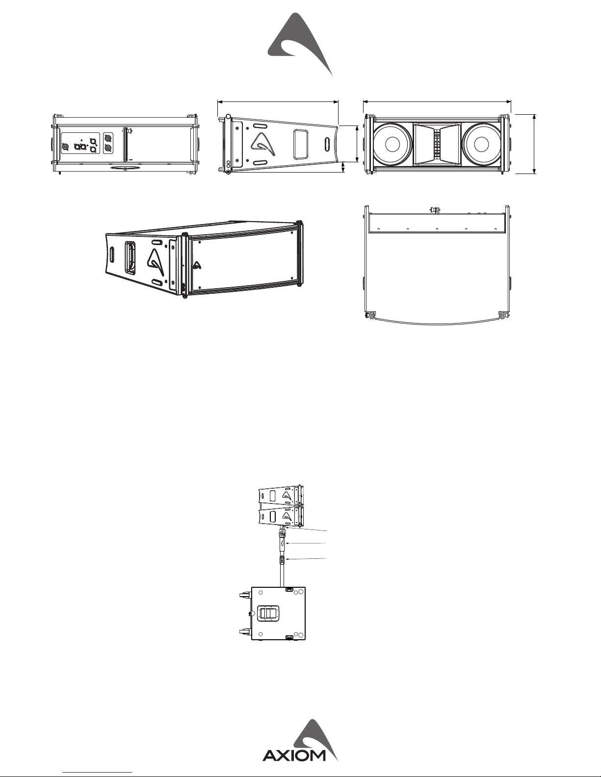
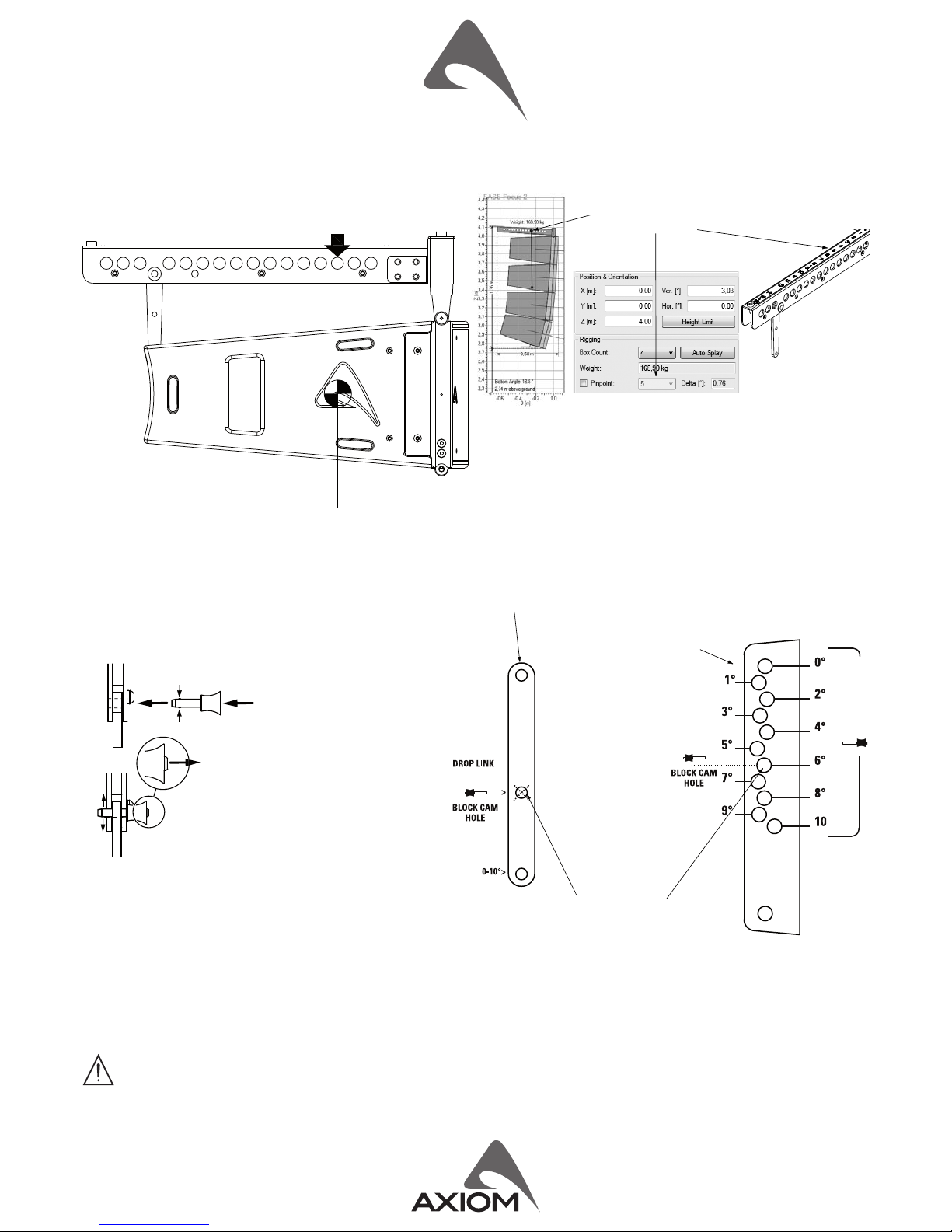
Coupling system in the front do not require any adjustment: using two
locking pins each loudspeaker box is xed to the previous. The sloed
bar in the back is inserted in a U-shaped frame which features a series
of numbered holes. Sliding the sloed bar in the U-shaped frame of the
next loudspeaker and inserng a locking pin in one of the numbered
holes, it is possible to adjust the relave splay angle between two
adjacent loudspeakers in the array column.
The opmal splay angles can be simulated using the EASE Focus 2
soware.
POWER AMPLIFIERS
The AX2065A is powered by DA SERIES digital power modules, a new generaon of CLASS D power amplier with digitally-controlled SMPS.
The innovave technology used for these ampliers (including also the use of a variable switching frequency) oers performances at the top of
the range, such as a superior sound denion at any audio frequency, very high dynamics also for low level signals and very low distoron even at
the maximum power The superior sound quality can be compared with top-of-the-range AB-class analog systems, while the DA modules feature
a higher dynamics, very compact size and light weight and eciency above 90%. The DA module employed for powering the AX2065A deliver
in an ultra-compact package a maximum power of 2000W, 1000W are delivered to the internal speakers, the other 1000W are delivered to the
AX2065P connected in parallel using the POWER OUT speakon connector.
SIGNAL PROCESSING
The system processing is based on the CORE DSP plaorm, which has been designed by the PROEL R&D Laboratories using one of the most
advanced SHARC DSP for audio applicaon. It features 40bit, 96kHz oang point resoluon and high quality 24bit AD/DA converters, for a perfect
signal integrity, a dynamic range in excess of 110dB and a superior sonic performance. Thanks to its massive processing power, the CORE plaorm
is capable of providing the most sophiscated algorithms for speaker processing, together with remote control and networking capability.
The PRONET control soware, working on a solid and reliable CANBUS based network protocol, provides an intuive interface for the remote
control of the whole system, with the possibility of eqing, delaying, increasing the protecons and monitoring the status of the amplier.
PRONET Network
PRONET soware has been developed in collaboraon with sound engineers and sound designers, in order to oer an “easy-to-use” tool to setup
and manage your audio system. With PRONET you can visualize signal levels, monitor internal status and edit all the parameters of each connected
device.
You can download the PRONET soware from the PROEL website at hp://www.proel.com (click on the link in the AX2065A product page).
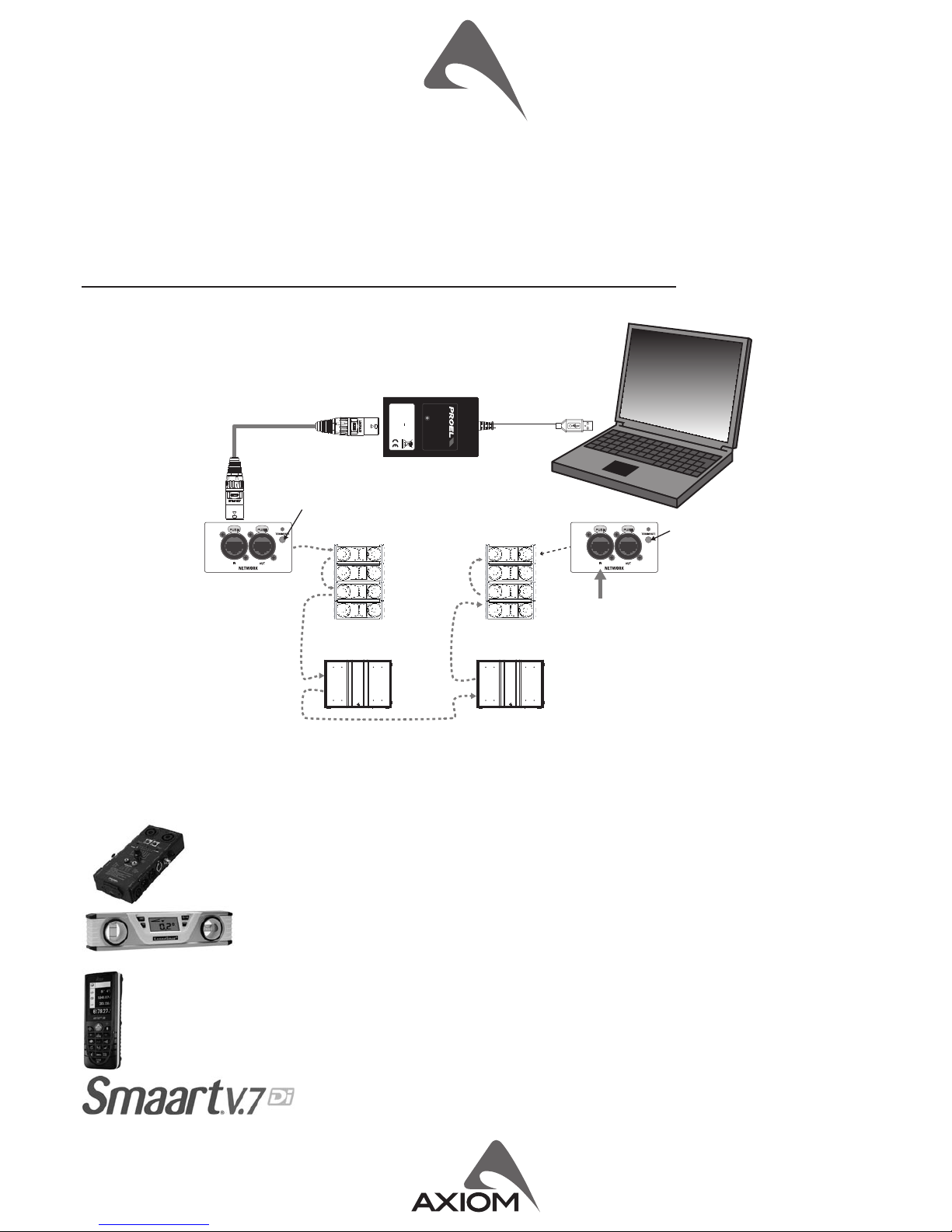
The AXIOM acve loudspeaker devices can be connected in a network and controlled by the PRONET soware. For the network connecon the
PROEL USB2CAN converter oponal accessory is needed. The rst me you connect a device with the USB2CAN converter, Windows O.S. will ask you
to install the driver les, which you can nd in the Driver folder within the Pronet applicaon folder (by default is C:\Program Files\Proel\Pronet\
Driver, or if you changed it <your path>\Driver). Please refer also to “Installaon” and “Drivers” paragraphs in the Pronet documentaon.
The PRONET NETWORK is based on a robust, reliable and fast communicaon protocol called CANBUS. The devices in a PRONET NETWORK are
connected together with a “linear bus topology”. The USB2CAN converter must be connected to the network input of the rst device, the network
output of the rst device is connected to the input of the second and so on. For the network connecons simple RJ45 cat.5 or cat.6 ethernet
cables can be used (please don’t confuse a ethernet network with a PRONET network these are completely dierent and must be fully separated
also both use the same kind of cable).
The beginning and the end of a PRONET NETWORK must be terminated. One side is terminated by the USB2CAN converter, the other side must
be terminated pressing the TERMINATE switch on the last device. All devices between these two points must have the TERMINATE switch lied.
Assign the ID number
To work properly in a PRONET network each connected device must have a unique idener number, called ID. By default the USB2CAN PC
controller has ID=0 and there can be only one PC controller. Every other device connected must have its own unique ID equal or greater than 1:
in the network cannot exist two devices with the same ID.
An ID number is assigned automacally to each devices when they are turned on for the rst me connected to a network.
In order to correctly assign a new available ID to each device for working properly in a Pronet network, follow these instrucons:
1. Switch o all the devices.
KPTSW215 STACKED ARRAY
max splay angle 10°
max splay angle 10°
max splay angle 10°
max splay angle 10°

2. Connect them correctly to the network cables.
3. “TERMINATE” the latest device in the network connecon.
4. Switch on the rst device keep pressed “PRESET” buon on the control panel.
5. Leaving the previous device switched on, repeat the previous operaon on the next device, unl the latest device is turned on.
The “Assign ID” procedure for a device makes the internal network controller to perform two operaons: reset the current ID; search the rst free
ID in the network, starng from ID=1. If no other devices are connected (and powered on), the controller assume ID=1, that is the rst free ID,
otherwise it searches the next one le free.
These operaons ensure that every device has it’s own unique ID, if you need to add a new device to the network you simply repeat the operaon
of step 4. Every device maintains its ID also when it is turned-o, because the idener is stored in the internal memory and it is cleared only by
another “Assign ID” step, as explained above. This means that if your network is made always of the same devices the assigning ID procedure must
be executed only the rst me the system is turned on.
For more detailed instrucon about PRONET see the PRONET USER’S MANUAL included with the soware.
Useful tools to set up properly a vercal array system
This is a list of tools that can be very useful to set properly a vercal array system.
CABLE TESTER
It is a good pracce to check all cables before each installaon, because even one faulty cable can compromise heavily the
system performance.
INCLINOMETER WITH LEVER
This tool can be used to verify the vercal array angle. It can be used at the top or at the boom of the array In this
case you have to sum all splay angles, so the maximum precision is needed for aiming the vercal array, parcularly
for long throw applicaons.
LASER DISTANCE METER
This instrument can be useful to measure the height of the vercal array and to know the distance between FOH-Subs and FOH-Array
for seng the delay me.
SMAART or similar acousc measurement system
These are useful to measure delays, phase and response of the system.
not pressed
pressed
last device
network
network
AX2065A
USB2CAN
PC NOTEBOOK
USB 2.0 port
AX2065A
AX2065P
AX2065A
AX2065P
SW215A
STATUS
CONVERTER
USB2CAN
CODE:
S/N:
RATINGS:
RoHS COMPLIANT
MADE IN ITALY
USB2CAN
00001
5V --- 200mA
EXAMPLE OF PRONET NETWORK WITH AX2065A AND SW215A

LIMITED WARRANTY
Proel warrants all materials, workmanship and proper operaon of this product for a period of two years from the original date of purchase. If any defects are found
in the materials or workmanship or if the product fails to funcon properly during the applicable warranty period, the owner should inform about these defects the
dealer or the distributor, providing receipt or invoice of date of purchase and defect detailed descripon. This warranty does not extend to damage resulng from
improper installaon, misuse, neglect or abuse. Proel S.p.A. will verify damage on returned units, and when the unit has been properly used and warranty is sll
valid, then the unit will be replaced or repaired. Proel S.p.A. is not responsible for any “direct damage” or “indirect damage” caused by product defecveness.
• This unit package has been submied to ISTA 1A integrity tests. We suggest you control the unit condions immediately aer unpacking it.
• If any damage is found, immediately advise the dealer. Keep all unit packaging parts to allow inspecon.
• Proel is not responsible for any damage that occurs during shipment.
• Products are sold “delivered ex warehouse” and shipment is at charge and risk of the buyer.
• Possible damages to unit should be immediately noed to forwarder. Each complaint for package tampered with should be done within eight days from product
receipt.
SAFETY INSTRUCTIONS
– To reduce the risk, close supervision is necessary when the product is used near children.
– Protect the apparatus from atmospheric agents and keep it away from water, rain and high humidity places.
– This product should be site away from heat sources such as radiators, lamps and any other device that generate heat.
– This product should be located so that its locaon or posion does not interfere with its proper venlaon and heang dissipaon.
– Care should be taken so that objects and liquids do not go inside the product.
– The product should be connected to a power supply mains line only of the type described on the operang instrucons or as marked on the product. Connect the
apparatus to a power supply using only power cord included making always sure it is in good condions.
– WARNING: The mains plug is used as disconnect device, the disconnect device shall remain readily operable.
– Do not cancel the safety feature assured by means of a polarized line plug (one blade wider than the other) or with a earth connecon.
– Make sure that power supply mains line has a proper earth connecon.
– Power supply cord should be unplugged from the outlet during strong thunderstorm or when le unused for a long period of me.
CE CONFORMITY
Proel products comply with direcve 2004/108/EC (EMC), as stated in EN 55103-1 and EN 55103-2 standards and with direcve 2006/95/CE (LVD), as stated in EN
60065 standard.
PROEL S.p.A. (World Headquarter) - Via alla Ruenia 37/43 - 64027 Sant’Omero (Te) - ITALY
Tel: +39 0861 81241 Fax: +39 0861 887862 www.proel.com
EXAMPLE OF INSTALLATION IN A THEATRE WITH BALCONY
Here below you can see an example of the use of dierent PRESETS in an AX2065 own array installed in a big theatre with balcony. The TOP BOXES
of the array are aiming at the balcony while the DOWN FILL box is aiming at the audience close to the stage.
TOP BOXES: the power level at the end of the
balcony is lower, as well as the high frequency
level.
DOWN FILL BOXES: the power level in the
proximity of the stage is higher, as well as the
high frequency level.
In order to opmize the array performances for this specic applicaon, the
PRESETS should be used in the following way.
Load the STANDARD preset in the central boxes.
Load the LONG THROW preset in the TOP 1 or 2 boxes, in order to compensate
the loss of power level and high frequencies of the program sent the upper
deck of the theatre.
Load the DOWN FILL / SINGLE BOX preset in the BOTTOM box in order to
smooth the high frequency content of the program sent to the audience close
to the stage.
TOP BOX
DOWN FILL BOX
+15 dB
+10
+5
0
-5
-10
-15
-20
-25
-30
-35 20 50 100 200 500 1K 2K 5K 10K 20K Hz
LONG THROW
STANDARD
SINGLE/DOWNFILL
AX2065A - PRESET RESPONSE
Table of contents
Other Axiom Speakers manuals

Axiom
Axiom QS8 v3 User manual

Axiom
Axiom ED150A User manual

Axiom
Axiom LFR1100 User manual

Axiom
Axiom ED120A User manual

Axiom
Axiom ED23PMKII User manual

Axiom
Axiom VP160 User manual

Axiom
Axiom Architectural W2 User manual

Axiom
Axiom Algonquin User manual

Axiom
Axiom VP180 v3 User manual

Axiom
Axiom T80 User manual