©Copyright 2020 Axiomtek Co., Ltd.
Version A1 November 2020
Printed in T iw n
9412K500000E
2
I/O Outlets
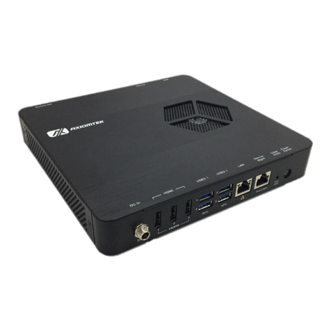
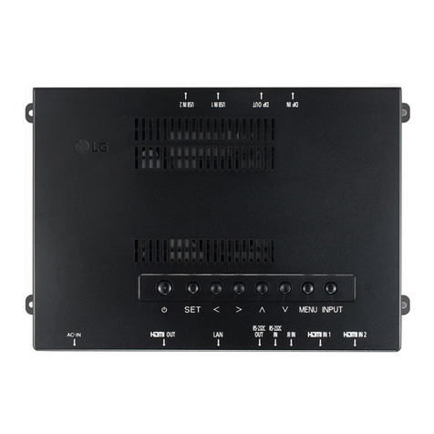
The following figures show I/O outlets on the DSP500-523.
Front View
Rear View
1 12VDC power input 7 Power Button
2 HDMI 1~3 8 COM port
3 USB 3.1 9 Line_Out
4 GbE LAN port 10
Antenna hole
5 Device management port 11
Remote switch
6 Clear EDID
©
Copyright 2020 Axiomtek Co., Ltd.
Version A1 November 2020
Printed in T iw n
9412K501000E
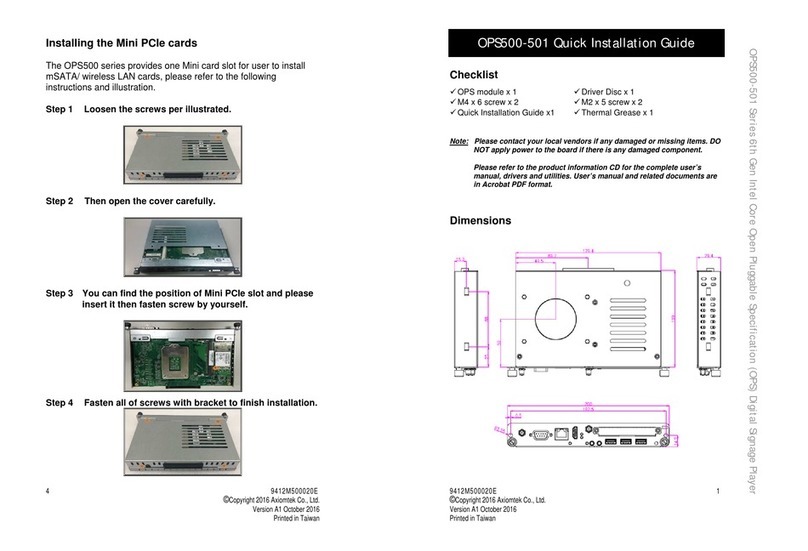
1 Installation of DIMM1 Memory
Step 1 Turn off the system and unplug the power cord.
Step 2 Turn the system upside down to locate screws at the bottom
and then loosen four screws.
Step 3 Located the DIMM1 socket on main board.
Step 4 Locate the memory module, insert a gold colored contact
into the socket and push the module end latches till locked.
Step 5 Put the top cover back and fasten four screws back onto the
system.
2 Installation of SDIMM2 Memory
Step 1 Turn off the system and unplug the power cord.
Step 2 Turn the system upside down to locate screws at the bottom
and then loosen four screws. Open the BOTTOM cover.
Step 3 Located the SDIMM1 socket on main board.
