AXIOMTEK ICO320-83C Series User manual

ICO320-83C Series
Robust Din-rail Fanless Embedded
System
User’s Manual

ii
Disclaimers
This manual has been carefully checked and believed to contain accurate
information. Axiomtek Co., Ltd. assumes no responsibility for any infringements of
patents or any third party’s rights, and any liability arising from such use.
Axiomtek does not warrant or assume any legal liability or responsibility for the
accuracy, completeness or usefulness of any information in this document. Axiomtek
does not make any commitment to update the information in this manual.
Axiomtek reserves the right to change or revise this document and/or product at any
time without notice.
No part of this document may be reproduced, stored in a retrieval system, or
transmitted, in any form or by any means, electronic, mechanical, photocopying,
recording, or otherwise, without the prior written permission of Axiomtek Co., Ltd.
Copyright 2017 Axiomtek Co., Ltd.
All Rights Reserved
December 2017, Version A1
Printed in Taiwan

iii
Safety Precautions
Before getting started, please read the following important safety precautions.
1. The ICO320-83C does not come equipped with an operating system. An
operating system must be loaded first before installing any software into the
computer.
2. Be sure to ground yourself to prevent static charge when installing the internal
components. Use a grounding wrist strap and place all electronic components in
any static-shielded devices. Most electronic components are sensitive to static
electrical charge.
3. Disconnect the power cord from the ICO320-83C before making any installation.
Be sure both the system and the external devices are turned OFF. Sudden
surge of power could ruin sensitive components. Make sure the ICO320-83C is
properly grounded.
4. Make sure the voltage of the power source is correct before connecting the
equipment to the power outlet.
5. Turn OFF the system power before cleaning. Clean the system using a cloth
only. Do not spray any liquid cleaner directly onto the screen.
6. Do not leave this equipment in an uncontrolled environment where the storage
temperature is below -45℃or above 85℃. It may damage the equipment.
7. Do not open the system’s back cover. If opening the cover for maintenance is a
must, only a trained technician is allowed to do so. Integrated circuits on
computer boards are sensitive to static electricity. To avoid damaging chips
from electrostatic discharge, observe the following precautions:
Before handling a board or integrated circuit, touch an unpainted portion of
the system unit chassis for a few seconds. This will help to discharge any
static electricity on your body.
When handling boards and components, wear a wrist-grounding strap,
available from most electronic component stores.
8. Caution
Risk of explosion if battery is replaced by an incorrect type dispose of used
batteries according to the instructions.
9. Warning
Hot Surface Do NoT Touch.
Restricted access area: The equipment should only be installed in a Restricted
Access Area.
10. This product is intended to be supplied by a Listed Power Adapter or DC power
source, output meets SELV, rated 12-24Vdc, minimum 1.6-0.81A, Tma = 25
degree C, and the altitude of operation = 5000m.Supported POE rated 24Vdc,
minimum 2.05A Tma = 25 degree C, and the altitude of operation = 5000m.
If need further assistance with purchasing the power source, please contact to
manufacturer for further information.

iv
Classification
1. Degree of production against electric shock: not classified
2. Degree of protection against the ingress of water: IP40
3. Equipment not suitable for use in the presence of a flammable anesthetic
mixture with air or with oxygen or nitrous oxide.
4. Mode of operation: Continuous
5. Type of protection against electric shock: Class I equipment
General Cleaning Tips
You may need the following precautions before you begin to clean the computer.
When you clean any single part or component for the computer, please read and
understand the details below fully.
When you need to clean the device, please rub it with a piece of dry cloth.
1. Be cautious of the tiny removable components when you use a vacuum cleaner
to absorb the dirt on the floor.
2. Turn the system off before you start to clean up the component or computer.
3. Never drop the components inside the computer or get circuit board damp or
wet.
4. Be cautious of all kinds of cleaning solvents or chemicals when you use it for
the sake of cleaning. Some individuals may be allergic to the ingredients.
5. Try not to put any food, drink or cigarette around the computer.

v
Cleaning Tools
Although many companies have created products to help improve the process of
cleaning your computer and peripherals users can also use household items to clean
their computers and peripherals. Below is a listing of items you may need or want to
use while cleaning your computer or computer peripherals.
Keep in mind that some components in your computer may only be able to be
cleaned using a product designed for cleaning that component, if this is the case it
will be mentioned in the cleaning.
Cloth: A piece of cloth is the best tool to use when rubbing up a component. Although
paper towels or tissues can be used on most hardware as well, we still recommend you
to rub it with a piece of cloth.
Water or rubbing alcohol: You may moisten a piece of cloth a bit with some
water or rubbing alcohol and rub it on the computer. Unknown solvents may be
harmful to the plastics parts.
Vacuum cleaner: Absorb the dust, dirt, hair, cigarette particles, and other
particles out of a computer can be one of the best methods of cleaning a
computer. Over time these items can restrict the airflow in a computer and
cause circuitry to corrode.
Cotton swabs: Cotton swaps moistened with rubbing alcohol or water are
excellent tools for wiping hard to reach areas in your keyboard, mouse, and
other locations.
Foam swabs: Whenever possible it is better to use lint free swabs such as foam
swabs.
Note: We strongly recommended that you should shut down the system before you start
to clean any single components.
Please follow the steps below:
1. Close all application programs
2. Close operating software
3. Turn off power
4. Remove all device
5. Pull out power cable

vi
Scrap Computer Recycling
If the computer equipments need the maintenance or are beyond repair, we strongly
recommended that you should inform your Axiomtek distributor as soon as possible
for the suitable solution. For the computers that are no longer useful or no longer
working well, please contact your Axiomtek distributor for recycling and we will make
the proper arrangement.
Trademarks Acknowledgments
Axiomtek is a trademark of Axiomtek Co., Ltd. IBM, PC/AT, PS/2, VGA are
trademarks of International Business Machines Corporation.
Intel®and Celeron®are registered trademarks of Intel Corporation.
MS-DOS, Microsoft C and QuickBASIC are trademarks of Microsoft Corporation.
VIA is a trademark of VIA Technologies, Inc.
SST is a trademark of Silicon Storage Technology, Inc.
UMC is a trademark of United Microelectronics Corporation.Other brand names and
trademarks are the properties and registered brands of their respective owners.

vii
Table of Contents
Safety Precautions................................................................................................ iii
Classification......................................................................................................... iv
General Cleaning Tips ..........................................................................................iv
Scrap Computer Recycling.................................................................................. vi
CHAPTER 1 INTRODUCTION................................................................................1
1.1 General Description...........................................................................1
1.2 System Specifications.......................................................................3
1.2.1 CPU ...................................................................................................................3
1.2.2BIOS ..................................................................................................................3
1.2.3System Memory ...............................................................................................3
1.2.4Display ..............................................................................................................3
1.2.5Ethernet Ports ..................................................................................................3
1.2.6PSE PD Ports....................................................................................................3
1.2.7Storages............................................................................................................3
1.2.8 Wireless ............................................................................................................3
1.2.9USB ...................................................................................................................4
1.2.10 COM ..................................................................................................................4
1.2.11 Power................................................................................................................4
1.2.12 Power & Reset Button.....................................................................................5
1.2.13 DIO ....................................................................................................................5
1.2.14WatchDog Timer (WDT) ..................................................................................5
1.2.15Restore BIOS Optimal Defaults (SW1) .....................................................5
1.2.16System LED......................................................................................................6
1.2.17Operation Temperature...................................................................................6
1.2.18Storage Temperature ......................................................................................6
1.2.19 Humidity ...........................................................................................................6
1.2.20 Weight...............................................................................................................6
1.2.21 Dimensions ......................................................................................................6
1.2.22 System I/O Outlets...........................................................................................6
1.3 Dimensions ........................................................................................7
1.4 I/O Outlets ..........................................................................................9
CHAPTER 2 HARDWARE INSTALLATION.......................................................11
2.1 Installing the Memory Module......................................................... 11
2.2 Installing the mSATA.......................................................................13
2.3 Installing Wireless Module.............................................................. 14
2.4 Installing Hard Disk ......................................................................... 17
2.5 Installing Din-rail Mounting............................................................. 18
CHAPTER 3 AMI UEFI BIOS UTILITY................................................................19
3.1 Entering Setup ................................................................................. 19
3.2 The Main Menu................................................................................. 19
3.3 Advanced Features.......................................................................... 20
3.4 Chipset Feature................................................................................ 36
3.5 Security............................................................................................. 37

viii
3.6 Boot Type .........................................................................................39
3.7 Save & Exit.......................................................................................41
APPENDIX A WATCHDOG TIMER......................................................................43
About Watchdog Timer ................................................................................... 43
How to Use Watchdog Timer.......................................................................... 43
APPENDIX B POWER BUTTON SETTING FOR WINDOW SOFTWARE ...45

ICO320-83C User’s Manual
Introduction
1
CHAPTER 1
INTRODUCTION
This chapter contains general information and detailed specifications of the ICO300. The
Chapter 1 includes the following sections:
General Description
System Specification
Dimensions
I/O Outlets
1.1 General Description
The fanless embedded system ICO320-83C is an ideal solution for communications control
and protocol converter applications in harsh environments. Designing for strict environment,
ICO320-83C adapts with extra low power consumption Intel Celeron N3350 (1.1GHz/2-
cores) processor, supporting industrial operating temperature range from -40℃to +70℃.
ICO320-83C offers a wide selection of I/O function, including 2 x USB, 1 x VGA, 1 x
COM port, 1 x CANBUS and 1 x DIO. Its compact size makes it suitable for DIN rail or
wall mount, allowing user put into control cabinet easily. With the compatibility with
Windows® 10, ICO320-83C provides programmers with a friendly environment for developing
application software at a lower cost.
ICO320-83C is a robust industrial-grade hardware design gateway and adopts the advanced
cooling system, supporting the mSATA and 2.5”SATA SSD (or HDD) makes it especially
suitable for field control & monitoring system solution for following markets such as:
Utility Industries (Water; Energy; Chemical Plant; Mining…)
Public Transportation Industries (Traffic/ Highway Control; Train/Bus Control…)
Homeland Security (Weather Monitoring/Alarm System…)

ICO320-83C User’s Manual
Introduction
2
Features
Fanless design
Wide temperature operation of -40℃- +70℃
Supports 4 10/100/1000 Base-T Ethernets
Supports 4 PSE PD compliant witj IEEE802.3at standard throuth LAN1~4(Optional)
2 COM Ports support RS-232/422/485
1 Wireless (USB and PCIe Interface)
Support one 2.5”SATA SSD(or HDD) and one mSATA(USB ,PCIe and SATA
interface)
Wide range 12–24V DC-in with terminal block (PSE only 24V)
8-bit programmable TTL level digital input/output ports
Din-rail mounting
Wall mounting (optional)
Passed CE with FCC testing
Embedded O.S. Supported
ICO320-83C supports Windows®10. For storage device, ICO320-83C supports
one mSATA and SATA.

ICO320-83C User’s Manual
Introduction
3
1.2 System Specifications
1.2.1 CPU
Onboard Intel ® Celeron N3350 (1.1 GHz/2-cores) processor.
1.2.2 BIOS
AMI (American Megatrends Inc.) UEFI (Unified Extensible Firmware Interface)
BIOS.
1.2.3 System Memory
One DDR3L 204-pin SO-DIMM (1.35V) slot.
Supports 1600 MHz max up to 8GB.
1.2.4 Display
A slim type 15-pin D-Sub connector as VGA connector.
Support VGA standards up to 1920x1200@60Hz
1.2.5 Ethernet Ports
LAN Chip: Intel Ethernet Controller I210.
Four RJ-45 connector, support 10/100/1000 Base-T Ethernet with 1.5KV
magnetic isolated protection.
1.2.6 PSE PD Ports
Compliant with IEEE 802.3at standard through LAN 1~4 ( Support total max
30W )
1.2.7 Storages
1 x mSATA (only half card)
1 x SATA.
1.2.8 Wireless
1 x Full size Mini Card slot supports module with USB and PCIe Interface.
1 x Half size Mini Card slot supports Module with USB, PCIe and SATA Interface.
1 x SIM Card Socket.
3 x Antenna holes.
ICO320-83C User’s Manual
Introduction
4
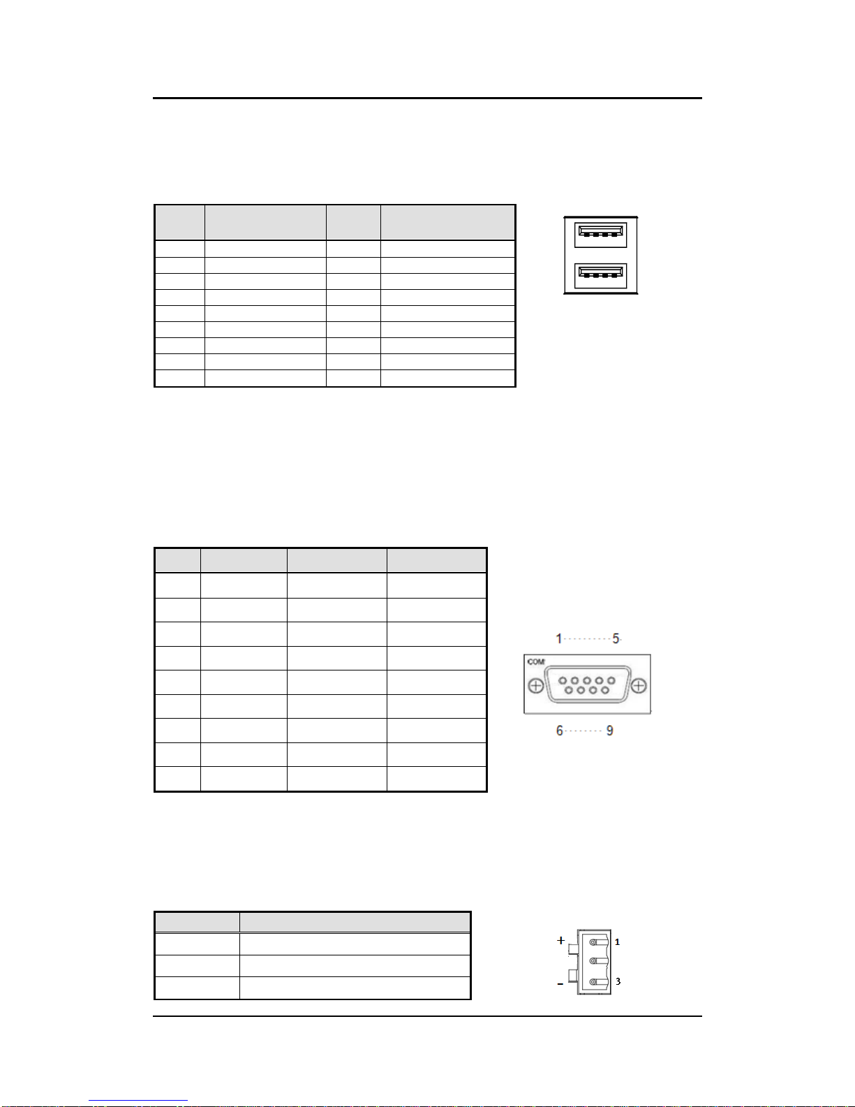
1.2.9 USB
2 x USB3.0
USB Pin Define :
Pin
Signal
USB3.0 Port 0
Pin
Signal
USB3.0 Port 1
1 2 3 4
5 6 7 8
1
VCC
10
VCC
2
D-
11
D-
3
D+
12
D+
4
GND
13
GND
5
SSRX2-
14
SSRX3-
6
SSRX2+
15
SSRX3+
7
GND
16
GND
8
SSTX2-
17
SSTX3-
9
SSTX2+
18
SSTX3+
1.2.10 COM
4 ports DB9 support RS-232/422/485 which can be selected by BIOS.
Supports Auto Flow Control in RS485 mode.
Supports High Speed Mode115.2 Kbps, Up to 1.5 Mbps
Serial Port Pin Define: (DB9 Male) as below
COM1~4
Pin
RS-232
RS-422
RS-485
1
DCD
TX-
Data-
2
RXD
TX+
Data+
3
TXD
RX+
--
4
DTR
RX-
--
5
GND
GND
GND
6
DSR
--
--
7
RTS
--
--
8
CTS
--
--
9
RI
--
--
1.2.11 Power
Wide-range 12 - 24V DC power input with terminal block.
OVP and Reverse protection.
Pin
Signal
1
+
2
NC
3
-
ICO320-83C User’s Manual
Introduction
5
1.2.12 Power & Reset Button
AT auto power on
Power button setting for software must be setted up firstly.
One Reset Button
Note: Power button setting for Window software is offered on APPENDIX B for
reference.
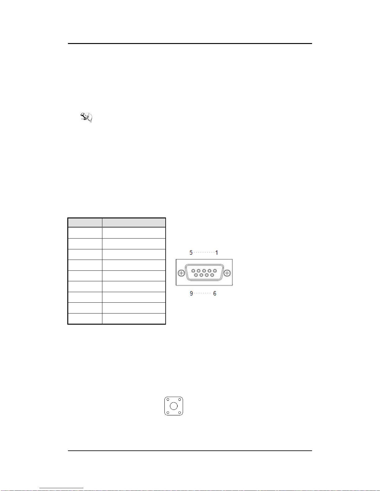
1.2.13 DIO
One DB9 female connector supports 8 bits TTL level programmable digital
input/output
The voltage of TTL is 5V
The programming is as follow:
- I/O sink current is 8~10mA (Output drive current ± 50 mA)
- Input/Output can be programmed
Pin
Signal
1
DIO0
2
DIO1
3
DIO2
4
DIO3
5
DIO4
6
DIO5
7
DIO6
8
DIO7
9
GND
1.2.14 WatchDog Timer (WDT)
1~255 seconds or minutes; up to 255 levels.
1.2.15 Restore BIOS Optimal Defaults (SW1)
Press the tact switch (SW 1) can restore BIOS optimal defaults.

ICO320-83C User’s Manual
Introduction
6
1.2.16 System LED
There are showed the LED’s indicators and functional descriptions.
LED Name
Description
Color
ACT
Indicate the storge status and it’s flashing when storge
access.
Orange
PWR
Indicate the Power status. When the DC input is acceptable,
the LED will ON.
Green
1.2.17 Operation Temperature
-40℃~ +70℃
1.2.18 Storage Temperature
-40℃~ +85℃
1.2.19 Humidity
10% ~ 95%
1.2.20 Weight
ICO320-83C 0.692 kg
ICO320-83C-POE 0.936 kg
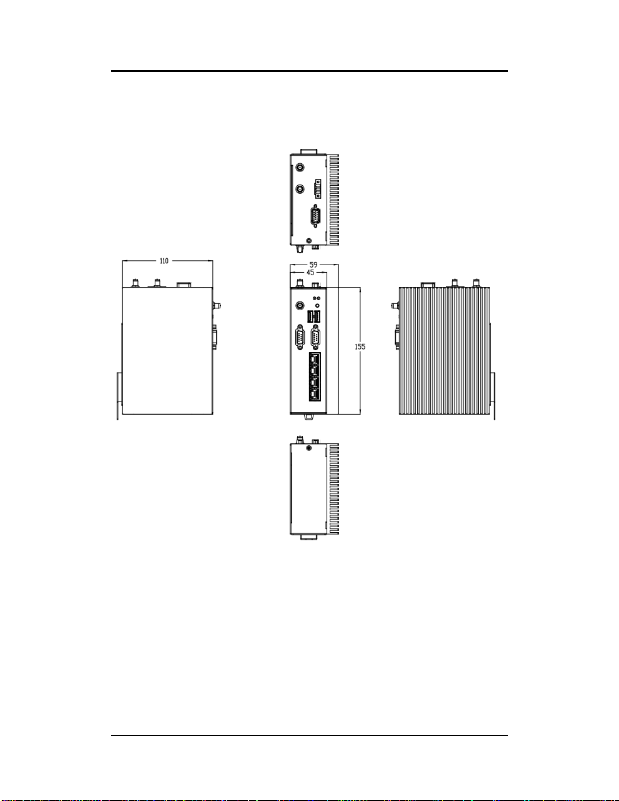
1.2.21 Dimensions
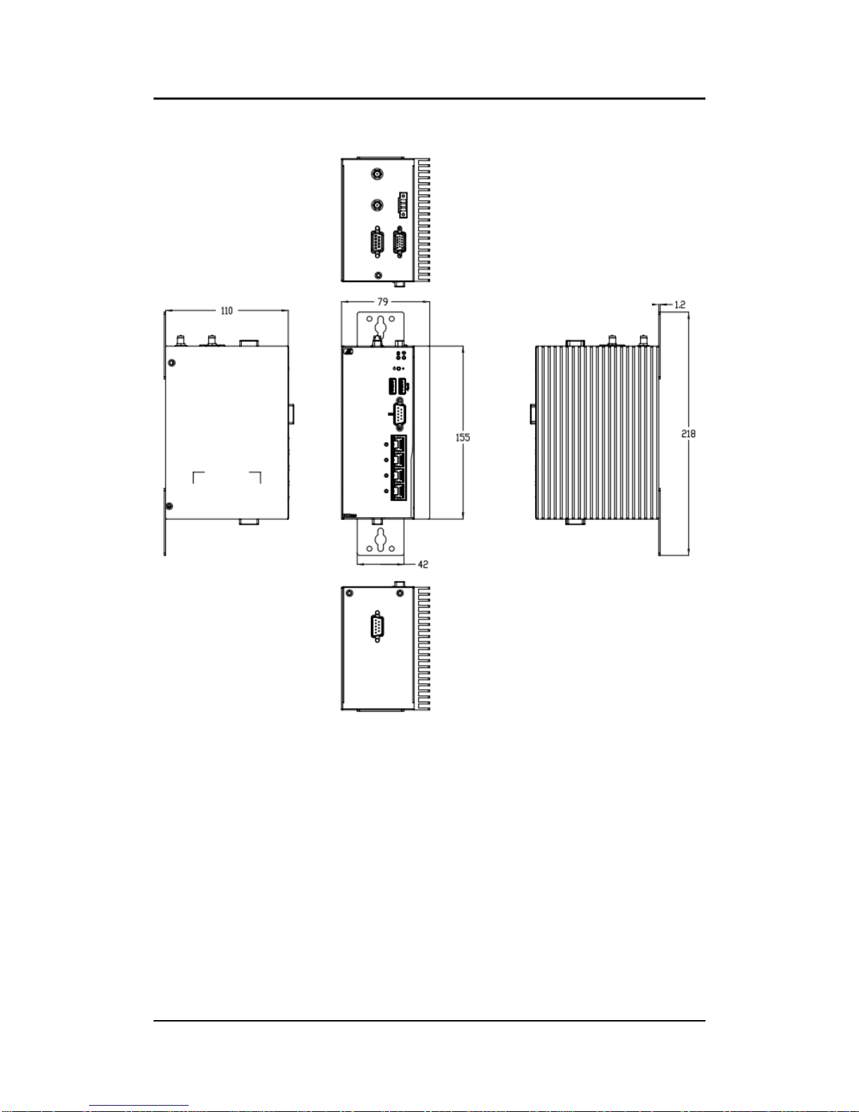
59mm (1.22”) (W) x110mm (3.93”) (D) x155mm (4.92”) (H)
79mm (1.22”) (W) x110mm (3.93”) (D) x155mm (4.92”) (H) (PSE)
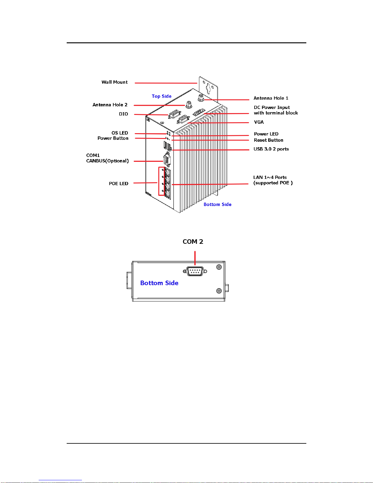
1.2.22 System I/O Outlets
Two 9-pin D-Sub male connectors,COM1.COM2
One 15-pin D-Sub female connector forVGA.
Four 10/100/1000 Base-T RJ-45 with 1.5KV magnetic isolated protection.
Four POE PD compliant with IEEE802.3at ( Optional ).
Two USB 3.0Ports
One DC Power Input with terminal block.
One 9-pin D-Sub Female connectors for DIO.
Two Antenna holes.
ICO320-83C User’s Manual
Introduction
7
1.3 Dimensions
The following diagrams show you dimensions and outlines of the ICO320-83C.
ICO320-83C User’s Manual
Introduction
8
The following diagrams show you dimensions and outlines of the ICO320-83C-PSE

ICO320-83C User’s Manual
Introduction
9
1.4 I/O Outlets
The following figures show you I/O outlets on front view and top view of the ICO320-
83C.
ICO320-83C User’s Manual
Introduction
10
The following figures show you I/O outlets on front view and top view of the ICO320-
83C-PSE.
ICO320-83C User’s Manual
Hardware Installation
11
CHAPTER 2
HARDWARE INSTALLATION
The ICO320-83C is convenient for your various hardware configurations, such as
Memory Module and mSATA. The chapter 2 will show you how to install the hardware.
It includes:
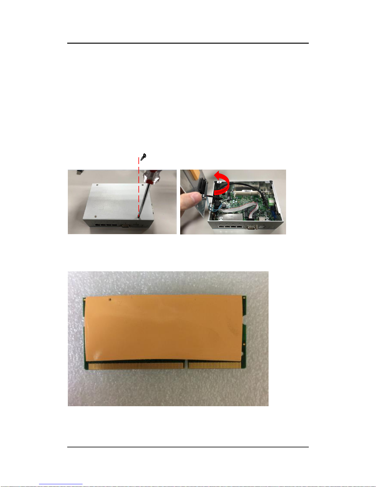
2.1 Installing the Memory Module
Step 1 Turn off the system.
Step 2 Loosen all screws of the cover and flip cover to the left.
Step 3 Put the thermal pad on memory module can increase cooling effect.

ICO320-83C User’s Manual
Hardware Installation
12
Step 4 Use two fingers to hold the memory module, and insert the gold figure
into the
slot and push the module down.
Step 5 The memory module is locked by two latches on the sides. We strongly
recommend using “LDC737” silicone on the two sides of the memory
for good ability of vibration.
Step 6 Put the cover back to the system, and fasten screws tight close the
chassis.
Table of contents
Other AXIOMTEK Media Converter manuals


