manuals.online logo
Brands
  1. Home
  2. •
  3. Brands
  4. •
  5. AXIOMTEK
  6. •
  7. Motherboard
  8. •
  9. AXIOMTEK CEM130 User manual

AXIOMTEK CEM130 User manual

Other manuals for CEM130

2

Other AXIOMTEK Motherboard manuals

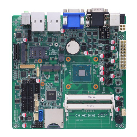
AXIOMTEK SBC8168 User manual

AXIOMTEK

AXIOMTEK SBC8168 User manual

AXIOMTEK CAPA520 User manual

AXIOMTEK

AXIOMTEK CAPA520 User manual

AXIOMTEK MANO321 Series User manual

AXIOMTEK

AXIOMTEK MANO321 Series User manual

AXIOMTEK MANO523 Series User manual

AXIOMTEK

AXIOMTEK MANO523 Series User manual

AXIOMTEK PICO300 User manual

AXIOMTEK

AXIOMTEK PICO300 User manual
AXIOMTEK SBC81206 Series User manual

AXIOMTEK

AXIOMTEK SBC81206 Series User manual

AXIOMTEK CAPA318 User manual

AXIOMTEK

AXIOMTEK CAPA318 User manual

AXIOMTEK NANO840 User manual

AXIOMTEK

AXIOMTEK NANO840 User manual

AXIOMTEK SBC81870 Series User manual

AXIOMTEK

AXIOMTEK SBC81870 Series User manual

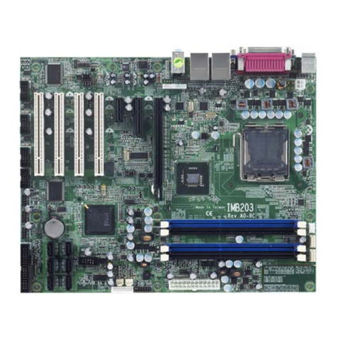
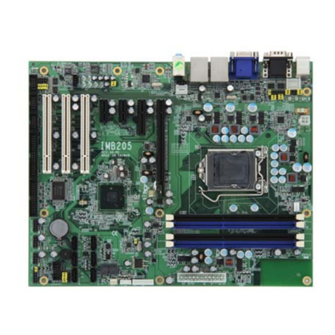
AXIOMTEK IMB205 Operational manual

AXIOMTEK

AXIOMTEK IMB205 Operational manual

AXIOMTEK wm5201 User manual

AXIOMTEK

AXIOMTEK wm5201 User manual

AXIOMTEK PICO821 Series User manual

AXIOMTEK

AXIOMTEK PICO821 Series User manual

AXIOMTEK imb500 User manual

AXIOMTEK

AXIOMTEK imb500 User manual

AXIOMTEK MANO310 Series User manual

AXIOMTEK

AXIOMTEK MANO310 Series User manual

AXIOMTEK STX88831 Series User manual

AXIOMTEK

AXIOMTEK STX88831 Series User manual

AXIOMTEK EP820 Series User manual

AXIOMTEK

AXIOMTEK EP820 Series User manual

AXIOMTEK Mano831 Series User manual

AXIOMTEK

AXIOMTEK Mano831 Series User manual
AXIOMTEK IMB200 User manual

AXIOMTEK

AXIOMTEK IMB200 User manual

AXIOMTEK MPC152-832 User manual

AXIOMTEK

AXIOMTEK MPC152-832 User manual

AXIOMTEK SBC86834 Series User manual

AXIOMTEK

AXIOMTEK SBC86834 Series User manual

AXIOMTEK SHB102 Series User manual

AXIOMTEK

AXIOMTEK SHB102 Series User manual

AXIOMTEK CEM820 Series User manual

AXIOMTEK

AXIOMTEK CEM820 Series User manual

AXIOMTEK EP100 User manual

AXIOMTEK

AXIOMTEK EP100 User manual

AXIOMTEK MANO560 Series User manual

AXIOMTEK

AXIOMTEK MANO560 Series User manual
Popular Motherboard manuals by other brands

Gigabyte MNJ190I-FH user manual

Gigabyte

Gigabyte MNJ190I-FH user manual

Biostar HI-FI-Z87X-3D Setup manual

Biostar

Biostar HI-FI-Z87X-3D Setup manual

Atmel SAM9753PIA-DK user guide

Atmel

Atmel SAM9753PIA-DK user guide

Coapt GEN2 Handbook

Coapt

Coapt GEN2 Handbook

Supero SUPER P4DL6 user manual

Supero

Supero SUPER P4DL6 user manual

Cypress CY3210-PSoCEVAL1 quick start guide

Cypress

Cypress CY3210-PSoCEVAL1 quick start guide

ASROCK B660M-HDV manual

ASROCK

ASROCK B660M-HDV manual

Fujitsu D2831 Short description

Fujitsu

Fujitsu D2831 Short description

Industrial Computers ADE-6050 user manual

Industrial Computers

Industrial Computers ADE-6050 user manual

Asus TUF Z270 MARK 2 manual

Asus

Asus TUF Z270 MARK 2 manual

DFI NB71-BC user manual

DFI

DFI NB71-BC user manual

ASROCK H61 Pro BTC user manual

ASROCK

ASROCK H61 Pro BTC user manual

Norco POS-7893 user manual

Norco

Norco POS-7893 user manual

Intel DG965MS specification

Intel

Intel DG965MS specification

Asus B85M-VIEW PAKER user manual

Asus

Asus B85M-VIEW PAKER user manual

Asus P5G41T-M LX V2 user manual

Asus

Asus P5G41T-M LX V2 user manual

Gigabyte GA-K8VT800-RH user manual

Gigabyte

Gigabyte GA-K8VT800-RH user manual

Gigabyte Z790M AORUS ELITE user manual

Gigabyte

Gigabyte Z790M AORUS ELITE user manual

manuals.online logo
manuals.online logoBrands
  • About & Mission
  • Contact us
  • Privacy Policy
  • Terms and Conditions

Copyright 2025 Manuals.Online. All Rights Reserved.

4 9418D130000E
©
Copyright 2020 Axiomtek Co., Ltd.
Versio A1 February 2020
Pri ted i Taiwa
Note: When installing CEM130 on CEB94011, please add stand-off and secure
with nut. Then, use the screws to secure the heatsink plate to the
CEM130.
Standoff
NUT
Quick Start
The basic procedures required to power on CEM130:
(1). Make sure the power is OFF before connecting the CEM130.
(2). Check to ensure the onboard switch SW1-1 and SW1-2 are set to
default (OFF position).
(3). Firmly install DDR4 SO-DIMM in SDIMM1 (on bottom side of the
board)/DIMM1 (on top side of the board) until fully seated. For single
memory channel configuration, install memory module in channel 0
(SDIMM1) DDR4 SO-DIMM socket. For dual memory channel
configuration, install memory modules of the same size, chip width,
density and rank in both channel 0 (SDIMM1) and channel 1 (DIMM1)
DDR4 SO-DIMM sockets.
(4). Attach heatsink to the CEM130, refer to section Installing Thermal
Solution.
(5). Install the CEM130 onto the suggested COM Express
TM
baseboard,
CEB94011
.
(6). Properly install all necessary peripheral devices such as hard disk,
display, keyboard and etc. to the baseboard.
(7). Firmly attach power supply to the baseboard power connector.
(8). Turn on the system power.
(9). Press power button on the baseboard to start CEM130.
CEM130 Quick Installation Guide
9418D130000E 1
©
Copyright 2020 Axiomtek Co., Ltd.
Versio A1 February 2020
Pri ted i Taiwa
Checklist

C
EM
130
Board x1
Note: Please contact your local vendors if any damaged or missing items. DO
NOT apply power to the board if there is any damaged component.
Module Layout
Top View
CEM130 COM Express
TM
Type 6 Compact Module
All manuals and user guides at all-guides.com
2 9418D130000E
©
Copyright 2020 Axiomtek Co., Ltd.
Versio A1 February 2020
Pri ted i Taiwa
Bottom View
Switch Settings
Before applying power to the CEM130, please make sure onboard
switches are in factory default positions.
Switch Description Setting
SW1
Auto Power On
Default: Disable
SW1-1 OFF
Restore BIOS Optimal Defaults
Default: Normal Operation
SW1-2 OFF
Connector
Connector Description
CN1
Fan Connector
SS
S
1
COM Express
TM
C
onnector
SS
S
2
COM Express
TM
Connector
S
DIMM1
Channel
0
DDR
4
SO
-
DIMM
Socket
DIMM
1
Channel
1
DDR
4
SO
-
DIMM
Socket
9418D130000E 3
©
Copyright 2020 Axiomtek Co., Ltd.
Versio A1 February 2020
Pri ted i Taiwa
Installing Thermal Solution
For thermal dissipation, a thermal solution enables the CEM130’s
components to dissipate heat efficiently. All heat generating components
are thermally conducted to the heatsink in order to avoid hot spots. Figure
below illustrates how to install the thermal solution on CEM130.
1. There is a protective plastic covering on the thermal pads. This must
be removed before the heatsink can be mounted.
2. Each heatsink is designed for a specific CEM module. The thermal
pads on the heatsink are designed to make contact with the necessary
components on the CEM module. When mounting the heatsink you
must make sure that the thermal pads on the heatsink make complete
contact (no space between thermal pad and component) with the
corresponding components on the CEM module. This is especially
critical for CEM modules that have higher CPU speeds (for example
1.46GHz or more) to ensure that the heatsink acts as a proper thermal
interface for cooling solutions.
3. Before installing the heatsink to the CPU module, please apply thermal
grease on the CPU die. This CPU module has assembly holes for
installing heatsink plate. Use the appropriate screws to secure the
heatsink plate to the CEM130. Be careful not to over-tighten the screws.
All manuals and user guides at all-guides.com